McQuay MicroTech II Operation Manual
Applied rooftop unit controller space comfort control (scc) used with mcquay models: rps, rfs, rcs, rpr, rfr, rdt, rds, rar and rah
Hide thumbs
Also See for MicroTech II:
- Operation manual (136 pages) ,
- Installation manual (58 pages) ,
- Installation and maintenance manual (48 pages)
Table of Contents
Advertisement
MicroTech II™
Applied Rooftop Unit Controller
Space Comfort Control (SCC)
© 2000 McQuay International
•
Used with McQuay models: RPS, RFS, RCS, RPR, RFR, RDT, RDS,
RAR and RAH
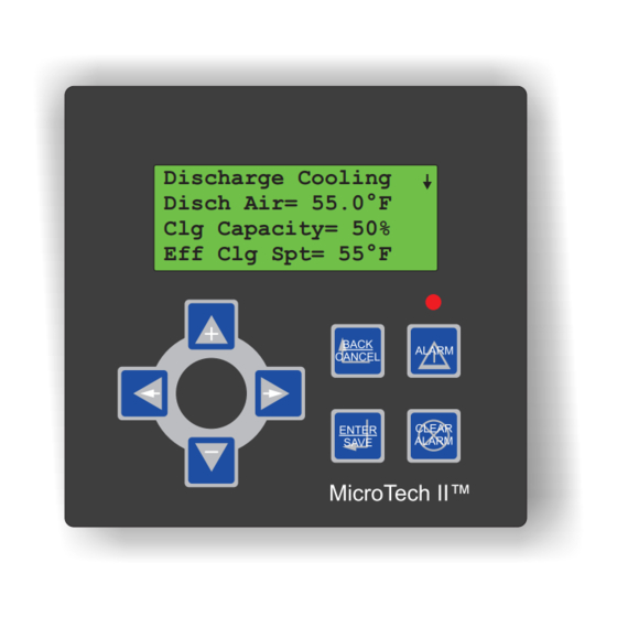
Discharge Cooling
Disch Air= 55.0°F
Clg Capacity= 50%
Eff Clg Spt= 55°F
Operation Manual
OM 138
Group: Applied Systems
Part Number: OM138
Date: April 2001
Advertisement
Table of Contents

Related Manuals for McQuay MicroTech II


Summary of Contents for McQuay MicroTech II
- Page 1 Date: April 2001 MicroTech II™ Applied Rooftop Unit Controller Space Comfort Control (SCC) • Used with McQuay models: RPS, RFS, RCS, RPR, RFR, RDT, RDS, RAR and RAH Discharge Cooling Disch Air= 55.0°F Clg Capacity= 50% Eff Clg Spt= 55°F...
-
Page 2: Table Of Contents
Configuring Remote Alarm Output..... 54 MicroTech II DDC Features ....99 Setting Alarm Limits. - Page 3 Document Number: OM 138 Revision: April 2001 McQuay, MicroTech II, and RoofPak are registered trademarks of McQuay International. Microsoft is a registered trademark of Microsoft Corporation. Windows is a trademark of Microsoft Corporation. Copyright © 2000 McQuay International. All rights reserved throughout the world.
-
Page 4: Introduction
Electric shock hazard. Can cause personal injury or equipment damage. This equipment must be properly grounded. Connections and service to the MicroTech II control panel must be performed only by personnel that are knowledgeable in the operation of the equipment being controlled. - Page 5 Extreme temperature hazard. Can cause damage to system components. The MicroTech II controller is designed to operate in ambient temperatures from -20°F to 125°F. It can be stored in ambient temperatures from -40°F to 140°F. It is designed to be stored and operated in relative humidity up to 95% (non-condensing).
-
Page 6: Getting Started
Getting Started The MicroTech II Applied Rooftop Unit Controller is a self- “Setup/Service”, “Active Alarms” and “Previous Alarms.” contained device that is capable of complete, stand-alone The name of each category generally describes the basic pur- operation. Information in the controller can be displayed and pose of the menus in the particular group. - Page 7 Figure 2: Keypad Accessible Menu Structure OM 138...
- Page 8 Figure2: Keypad Accessible Menu Structure (Continued) OM 138...
- Page 9 Figure2: Keypad Accessible Menu Structure (Continued) OM 138...
-
Page 10: Display Format
4545 and enter the new value, the following proce- dure is used: The information stored in the MicroTech II controller menu structure can be viewed on the 4-line by 20-character LCD display. The current menu is displayed on the top line and up to three menu items are displayed on the next three lines (refer to Figure 3). -
Page 11: Keypad Functions
The MicroTech II controller keypad consists of 8 pressure sensitive membrane switches. Refer to Figure 1 on page 6. The following are descriptions of these keys and their functions. - Page 12 2. Assuming the blinking cursor is positioned on the Sys- holding the Down Arrow (-) causes the value to decre- tem Summary menu, pressing the Down Arrow (-) key ment rapidly. twice changes the cursor position to the Temperature menu. 8.
-
Page 13: Keypad/Display Menu Reference
The following is a brief description of each menu and menu rapidly. item within the rooftop MicroTech II menu structure. Tables are included which show every menu, item, and field in the menu structure of the program. These menus and items can all be displayed with the keypad/display. - Page 14 Clg Capacity. Clg Capacity= is a status only item which regarding this parameter, refer to “Auto/Manual Operation” indicates the percentage of the unit maximum cooling capac- on page 45. ity currently operating. Bypass Time. Bypass Time= is an adjustable item which Htg Capacity.
- Page 15 Table 2: System Summary Menus Menu Name Menu Item Name Factory Default Value Field Number Range Off Unoc Off Man Off Net Off Sw Off Alm Calib Startup Recirc Fan Only UnitStatus Econo Cooling Heating Min DAT UnocEcon UnocClg UnocHtg Man Ctrl Clg Capacity 0-100%...
-
Page 16: Airflow
Table 2: System Summary Menus (Continued) Menu Name Menu Item Name Factory Default Value Field Number Range Occupancy Unocc Bypass Unocc Occ Mode Auto Bypass Auto Occupancy None Int Sched Occ Src Net Sched Occ Mode Remote Sw Bypass Time 0 min 0 -300 min Norm... -
Page 17: Temperature
Table 3: Airflow Menus Menu Name Menu Item Name Factory Default Value Field Number Range Flow Flow Status NoFlow Disch Fan Airflow Summary RF/EF Fan Fan Operation Bldg Press -0.250 - 0.250 “WC BldgSP Spt 0.050 “WC -0.250 - 0.250 “WC Bldg Pressure BSP Db 0.010 “WC... - Page 18 Htg Capacity. Htg Capacity= is a status only item which the optional unit space air temperature sensor input. Refer to “Zone (Space) Temperature Sensor” on page 56. indicates the percentage of the unit maximum heating capac- ity currently operating. Note: If an optional space temperature sensor is not installed, the Space Sensor= item in the Unit Con- Eff Htg Spt.
- Page 19 Note: An optional space temperature sensor is required the controller to limit the discharge air temperature while for unoccupied heating operation. controlling the space or zone conditions. For detailed infor- mation on discharge air temperature control, refer to “Econo- UnoccHtgDiff. UnoccHtgDiff= is an adjustable item which mizer”...
- Page 20 (0-30% outdoor air units) or “Minimum Ventilation Control” 0-100% refers to 0-100% of 10VDC. For detailed informa- on page 70 (economizer units) as applicable. tion regarding minimum ventilation control, refer to “Mini- mum Ventilation Control” on page 68 (0-30% outdoor air DesignFlow.
- Page 21 EconChgovr T= value, the OA Ambient= item indicates Spt= in the Zone Heating menu. For detailed information “High” and economizer operation is disabled. For detailed regarding modulating heating operation, refer to“Heating: information regarding economizer changeover operation Modulating” on page 80. refer to “Economizer Changeover Method”...
- Page 22 Energy Rec. Energy Rec= is an adjustable item which stop the exhaust fan when a unit is equipped with an optional energy recovery system. turns the optional energy recovery system on and off. Table 4: Temperature Menus Menu Name Menu Item Name Factory Default Value Field Number Range...
-
Page 23: Humidity
Table 4: Temperature Menus (Continued) Menu Name Menu Item Name Factory Default Value Field Number Range OA Damper Pos 0-100% Eff Min OA Pos 0-100% OA Flow 0-50000 CFM OA Ambient High None Auto MinOA Type None Ext mA Ext V DesignFlow MinOA Pos 0-100%... -
Page 24: Schedules
Table 5: Humidity Menus Menu Name Menu Item Name Factory Default Value Field Number Range Dehumid Status Rel Humidity Dew Point None Dehumid Method None Dehumidification DewPnt RH Setpoint 0-99% DewPoint Spt 50°F 0.0-99.0°F RH Db 0-10% DewPnt Db 2°F 0-10°F Dehum Method. - Page 25 each day of the holiday period, the holiday schedule entered tion where the controller “learns” and updates the optimal in the Daily Schedules menu is used. start parameters automatically based on previous results. Hol 1 through Hol 16. Hol 1= through Hol 16= are Htg Rate.
-
Page 26: Setup/Service
Table 6: Schedules Menus (Continued) Menu Name Menu Item Name Factory Default Value Field Number Range Jan-Dec 01-31 Hol 1 N/A-N/A Jan-Dec 01-31 Hol 2 Same As Hol 1 Same As Hol 1 Same As Hol 1 Hol 3 Same As Hol 1 Same As Hol 1 Same As Hol 1 Hol 4... - Page 27 RF/EF Ctrl. RF/EF Ctrl= is an adjustable item used to tistage electric heat. Refer to “Software Identification and Configuration” on page 102 select the type of return or exhaust fan airflow control to be used. If the unit is equipped with return fan inlets vanes or a ERecB ID.
- Page 28 ERecovery. ERecovery= is a status item which indicates energy recover have been operating. This information can be used for scheduling maintenance and monitoring unit opera- the hours that the optional energy recovery system has been tion. in operation. This value accumulates to 50,000 hours before rolling over.
- Page 29 The Compressor Setup menu contains several adjustable Heating menus. For detailed information regarding PID con- parameters than affect the compressor and condenser fan trol parameters, refer to “MicroTech II DDC Features” on staging on units equipped with compressorized cooling. For page 99.
- Page 30 Discharge Cooling menu. For detailed information Cond Fan2 Spt. Cond Fan2 Spt= is an adjustable item regarding these control parameters, refer to “MicroTech II used to set the outdoor air temperature point above which the DDC Features” on page 99.
- Page 31 DesignFlow apparatus, actuator. For detailed information on this PID control param- refer to the applicable model-specific installation and main- eter, refer to “MicroTech II DDC Features” on page 99. tenance manual (refer to Table 1 on page 4). Energy Rec Setup RH Lvl Pos.
- Page 32 Alarm. Alarm= is an adjustable item used to manually turn function. For detailed information regarding the dehumidifi- cation control function, for detailed information regarding the Remote Alarm Output (MCB-BO4) on and off. the dehumidification function, refer to “Dehumidification” OA Damper. OA Damper= is an adjustable item used to on page 85.
- Page 33 Fan Fail. Fan Fail= is an adjustable item used to determine Frost-Ckt2. Frost-Ckt2= is an adjustable item used to the action of the Remote Alarm Output when the Fan Fail determine the action of the Remote Alarm Output when the fault occurs.
- Page 34 Alarm Out Warnings Ckt2 H/W. Ckt2 H/W= is an adjustable item used to deter- mine the action of the Remote Alarm Output when the Ckt2 The Alarm Out Warnings menu contains parameters for H/W warning occurs. determining the action of the Remote Alarm Output (MCB- BO4) when “warning”...
- Page 35 Table 7: Setup/Services Menus Menu Name Menu Item Name Factory Default Value Field Number Range AHU ID xxxxxxxxxx CompB1 ID xxxxxxxxxx CompB2 ID xxxxxxxxxx GenCB ID xxxxxxxxxx HtgB ID xxxxxxxxxx ERecB ID xxxxxxxxxx KP ID xxxxxxxxxx Calibrate Mode Space Sensor Unit Configuration EFT Sensor None...
- Page 36 Table 7: Setup/Services Menus (Continued) Menu Name Menu Item Name Factory Default Value Field Number Range 00 - 23 Time 00 -59 00 - 59 Time/Date Mon - Sun 01-31 Date Jan - Dec year 1999-2155 BSP Propbd 1.0 “WC 0.1-30.0 “WC Bldg Static P Setup BSP IntTime...
- Page 37 Table 7: Setup/Services Menus (Continued) Menu Name Menu Item Name Factory Default Value Field Number Range EWhl Propbd 30 °F 1-100 °F Energy Rec Setup EWhl IntTime 100 sec 0-3600 sec EWhl Period 30 sec 1-3600 sec Occupied Dehum Ctrl Occupied Always Minimum Stages...
-
Page 38: Active Alarms
Table 7: Setup/Services Menus (Continued) Menu Name Menu Item Name Factory Default Value Field Number Range Freeze Slow Fast Slow OAT Sensor Slow Same As Freeze Space Sensor Slow Same As Freeze Return Sensor Slow Same As Freeze Ent Fan Sens Slow Same As Freeze Lo Airflow... - Page 39 Active Alarm 3 menus and items. For detailed information regarding alarm handling, refer to “Alarm Monitoring” on page 51 and The Active Alarm 3 menu provides details regarding the “Alarm Control” on page 91. third highest priority active alarm. Active Alarm 1 Alarm Name.
- Page 40 Table 8: Active Alarm Menus Menu Name Menu Item Name Factory Default Value Field Number Range None Freeze (Fault) Smoke (Fault) Space Sensor (Fault) Return Sensor (Fault) Disch Sensor (Fault) Hi Return Tmp (Fault) Hi Disch Tmp (Fault) Lo Disch Tmp (Fault) Fan Fail (Fault) OA Dmpr Stuck (Fault) Freeze (Problem)
- Page 41 Table 8: Active Alarm Menus (Continued) Menu Name Menu Item Name Factory Default Value Field Number Range Alarm Name Same As Active Alm 1 Fault-Active Active Alarm 2 Alarm Type Problem- Active Warning- Active Alarm Date and Time dd-mmm-yy/hh:mm:ss Alarm Name Same As Active Alm 1 Fault- Active Active Alarm 3...
-
Page 42: Previous Alarms
Previous Alarms Alarm Name. Alarm Name= is a status only item that iden- tifies the name of Previous Alarm 1. Menus in the Previous Alarms category contain alarm infor- mation for up to 4 previous alarms. Table 9 lists all menus Alarm Type. -
Page 43: Operator's Guide
The following “Operator’s Guide” sections provide informa- the closed to open position. When the unit is equipped with tion regarding the day-to-day operation of the MicroTech II compressorized cooling, the percentage value changes incre- Applied Rooftop Unit Controller. Topics covered are such mentally based on the number operating cooling stages. -
Page 44: Htg Status
Off Net 1. The unit is not equipped with an economizer or the out- door air is not suitable for free cooling (OA Ambient= The Clg Status= parameter indicates “Off Net” when cool- parameter in the OA Damper menu indicates “High”). ing is disabled by a network signal affecting the Appl Mode= 2. -
Page 45: Auto/Manual Operation
WARNING Electric shock and moving machinery hazard. Can cause personal injury or death. When the unit is in any Off operating state, power is not removed from the unit controller or components. Remove power by turning off the disconnect-switch before servicing line voltage equipment or entering the unit. -
Page 46: Occupancy
Heat/Cool tion is activated. Refer to “Unoccupied Control” on page 89. The unit is in the unoccupied mode if all of the following When the Application Mode is set to “Heat/Cool”, both conditions are true: cooling and heating operation are allowed to operate as required to maintain the cooling and heating set points. -
Page 47: Occ Src
Bypass 1. The Occupancy= parameter is “Occ” and the unit starts if a field supplied external time clock or a tenant over- When the Occupancy Mode is set to “Bypass”, the Bypass ride switch signal in the form of a set of dry contacts is Time= parameter is set to the Bypass Time Increment= value. -
Page 48: Bypass Time (Tenant Override)
Bypass Time (Tenant Override) trolled by any active scheduling function (internal time clock schedule, optimal start function, one time event schedule, or Table 13: Programmable Parameters an optional network schedule). If there is no active schedul- ing function, the unit remains in the unoccupied mode. For Keypad/Display ID detailed information refer to “External Time Clock or Tenant Parameter Name... -
Page 49: Setting Controller Date And Time
“00:00-00:00” (this is the Date= dd-mm-yyyy Current Date default setting). The MicroTech II controller uses the date and time to exe- Holiday Scheduling cute its internal scheduling functions. Once set, the battery backed internal time clock keeps the current time regardless Table 17: Programmable Parameters of whether or not power is being supplied to the unit. -
Page 50: Optimal Start
Date/Time and One Event Ending Date/Time parameters the Flag is set to “Yes”, the controller calculates an early start unit starts up and runs continuously regardless of any other time before each normally scheduled start. The controller time scheduling functions. For example, assume that a space uses the start history, outdoor air temperature, and space served by the unit is occupied for a special event on March temperature to determine when the unit should start. -
Page 51: External Time Scheduling
About Alarms tion. This is accomplished by a field supplied external time The MicroTech II Applied Rooftop Unit Controller is pro- clock signal in the form of a set of dry contacts wired across grammed to monitor the unit for alarm conditions. Alarm terminals 101 and 102 on the unit field terminal block TB2 conditions are categorized in three types: “faults”, “prob-... -
Page 52: Remote Alarm Indication
(no remote indication of the The MicroTech II control system includes a Remote Alarm alarm). Refer to “Configuring Remote Alarm Output” on Output (MCB-B04) to provide remote indication of alarm page 54. -
Page 53: Local Alarm Indication (Keypad/Display)
Figure 6: Active and Previous Alarm Menu Display Menu Line Active Alarm 1 Previous Alarm 1 Alarm Name Item Line Dirty Filter Dirty Filter Alarm Type Item Line Warning-Active Warning-Clear Alarm Date/Time Item Line 12-Mar-00 04:50:49 12-Mar-00 05:15:34 Local Alarm Indication (Keypad/Display) 1. -
Page 54: Remote Alarm Clearing
menu. Pressing the Right Arrow key five more times controller. This clears the active alarm and returns the changes the display to the Previous Alarm 8 menu. unit to normal operation if no other alarms are active. Remote Alarm Clearing Although it is always recommended that active alarms be cleared at the unit via the keypad/display, there are other 5. - Page 55 Table 21: Programmable Parameters (Continued) Keypad/Display ID Parameter Name Menu Name Item Name Freeze= Slow Freeze Problem Remote Output Setup OAT Sensor= Slow OAT Sensor Problem Remote Output Setup Space Sensor= Slow Space Sensor Problem Remote Output Setup Return Sensor= Slow Return Sensor Problem Remote Output Setup Ent Fan Sensor= Slow Ent Fan Sensor Problem Remote Output Setup...
-
Page 56: Setting Alarm Limits
(or zeroed). The following is a description of the The optional space temperature sensor is required to take Calibrate Mode procedure. advantage of the MicroTech II unoccupied heating (night When the Calibrate Mode Flag is set to “Yes”, the Occu- setback) and cooling (night setup and purge) functions. -
Page 57: Miscellaneous Service Parameters
Miscellaneous Service Parameters design only for a building static pressure input. There is no “first sensor” location. Table 25: Programmable Parameters The Second Pressure Sensor Present Flag should be set to “None” when the Return/Exhaust Fan Capacity Control Flag Keypad/Display ID is set to “None”... -
Page 58: Control Timer Settings
MWU operating state applicable on units with return air (100% OA units have no MWU operating Several MicroTech II internal control timers can be adjusted state). Whenever a unit with return air leaves the Recirc via the keypad/display Timer Settings menu. The following operating state, it enters the MWU operating state if the Ctrl sections describe these timers. -
Page 59: Manual Output Control
Manual Output Control Control Mode Flag is set to “Yes” and this parameter is set to “Off” the discharge air fan is turned off. Table 27: Programmable Parameters RF/EF Fan Keypad/Display ID The Manual Return/Exhaust Fan Control Flag is used to Parameter Name Menu Name Item Name... - Page 60 close cooling valve output (MCB-BO7) is turned on and the open return or exhaust inlet vanes output (MCB-BO16) is cooling valve strokes closed continuously. When the Manual turned on and the vanes stroke open continuously. When the Control Mode Flag is set to “Yes” and this parameter is set to Manual Control Mode Flag is set to “Yes”...
-
Page 61: Description Of Operation
Description of Operation The following sections describe how the various zone (or Table 28 shows the all the normal operating states and the space comfort) control unit processes function to maintain status information they summarize temperature, ventilation and pressure control. The “Operat- Operating State Descriptions ing States and Sequences”... - Page 62 Off Sw. The unit operating state is Off Sw when a field sup- Operation Output (MCB-BO3) is closed and in building plied and installed switch across terminals 101 and 104 on pressure control applications, normal return fan capacity the unit field terminal block (TB2) is in the on or closed control is maintained.
- Page 63 UnocClg Note: 100% outdoor air units do not transition through the MWU operating state. The unit enters the UnocClg operating state when unoccu- pied cooling (night setup) operation is required and the econ- For detailed information regarding morning warm-up heat- omizer is either disabled, not present, or already fully ing operation, refer to “Heating: Multistage”...
-
Page 64: Operating State Sequence Chart
Figure 7: Operating State Sequence Chart Operating State Sequence Chart During the Startup operating state, the Fan Operation Output (MCB-BO3) is closed to indicate that the fans are about to Operating states and the transitions between them help to start. On units with return fan inlet vanes, the vanes are describe the unit sequences of operation. -
Page 65: Fan Startup
Fan Startup As soon as the unit leaves the Startup operating state, the dis- charge fan starts and the Airflow Check Timer is reset and Table 30: Programmable Parameters starts timing down. This timer value is a fixed two minutes. Keypad/Display ID The Fan Fail fault which indicates loss of airflow is pre- Parameter Name... -
Page 66: Temperature Control
Temperature Control Once enabled by the “Control Temperature” cooling or heat- ing capacity control operates as described in “Economizer” Table 31: Programmable Parameters on page 68, “Cooling: Multistage” on page 72, “Cooling: Modulating” on page 77, “Heating: Multistage” on page 78, Keypad/Display ID or “Heating: Modulating”... - Page 67 Figure 8: Illustrative Heat/Cool Changeover Operating Sequence Cooling Enabled Effective Cooling Enable Set Point Cooling Enable Dead Band Fan Only Heating Enable Dead Band Effective Heating Enable Set Point Heating Enabled Time Cooling to Fan Only. When cooling is active and the ture low limit function if the discharge air temperature gets “Control Temperature”...
-
Page 68: 0-30% Outdoor Air Damper Control
0-30% Outdoor Air Damper Control Economizer Temperature Control Minimum Ventilation Control Table 33: Programmable Parameters Table 32: Programmable Parameters Keypad/Display ID Keypad/Display ID Parameter Name Parameter Name Menu Name Item Name Menu Name Item Name Effective Cooling Minimum Outdoor Eff Clg Spt= ____ °F Enable Set Point MinOA Type= None Damper Position... -
Page 69: Economizer Changeover Method
PID control loop parameters, below the Effective Cooling Enable Set Point by more than refer to “MicroTech II DDC Features” on page 99. half the Cooling Enable Dead Band and either of the follow- ing are true: Effective Discharge Cooling Set Point Adjustment. -
Page 70: Minimum Ventilation Control
Minimum Ventilation Control with the return air enthalpy. All units with economizers are at least equipped with the outdoor air enthalpy version. The comparative version is optional. In either case a binary input Table 35: Programmable Parameters (MCB-BI11) is delivered to the controller indicating whether Keypad/Display ID or not outdoor air is suitable for free cooling. - Page 71 tion Set Point and the Effective Minimum Outdoor Damper Note: The Minimum Outdoor Damper Position Reset Position Set Point Maximum Limit in a number of ways. Flag automatically reverts to “None” if the Design- These are described as follows: Flow= parameter is set to “Yes” Unoccupied Operation Network OA Reset When the Minimum Outdoor Damper Position Reset Flag is...
-
Page 72: Cooling: Multistage
2. If the DesignFlow Flag is set to “Yes”, normal control VFD. To overcome this type of problem, the MicroTech II resumes if the Flow Ratio exceeds 100% by more than... -
Page 73: Low Ambient Cooling Lockout
Low Ambient Cooling Lockout Note: Unless it is set by a signal from an optional space temperature sensor, the Effective Cooling Enable Set Point is set by the controller equal to the Cool- Table 37: Programmable Parameters ing Enable Set Point. Keypad/Display ID Parameter Name The controller activates the first stage of mechanical cooling... - Page 74 Circuit Lead/Lag When a capacity decrease is required and the number of operating compressors in both circuits is the same, the oper- 2 Compressors/2 Stages or 4 Compressors/4 ating compressor with the highest run hour total in the “lag” Stages. The “lead” refrigeration circuit can be selected by circuit is turned off.
- Page 75 2 Compressors/4 Stages, 2 Compressors/6 Stages on circuit #1 with the fewest run hours is turned on. When a further increase is required, the other “small” compressor on or 4 Compressors/8 Stages. When a capacity increase circuit #1 is turned on. When a further increase is required, is required and the “lead”...
-
Page 76: Condenser Fan Control
“small” compressors on circuit #1 would cycle on denser Fan Set Point by more than the Condenser Fan Differ- and off (based on run hours) to maintain the load. ential. The fourth condenser fan in each operating circuit is turned on when the OA Temp= value rises above the Fourth Generic Condensing Unit Staging Condenser Fan Set Point and is turned off when the OA When a unit is equipped with a DX cooling coil and is inter-... -
Page 77: Cooling: Modulating
Dead Band Discharge Cooling trol. For detailed information regarding tuning PID control Minimum Discharge Min Clg Spt= 55.0 ºF loop parameters, refer to “MicroTech II DDC Features” on Cooling Set Point page 99. Maximum Discharge Max Clg Spt= 65.0 ºF Cooling Set Point Effective Discharge Cooling Set Point Adjustment. -
Page 78: Heating: Multistage
Temperature Control factory default values for these parameters provide the best control. For detailed information regarding tuning PID con- Table 41: Programmable Parameters trol loop parameters, refer to “MicroTech II DDC Features” Keypad/Display ID on page 99. Parameter Name Menu Name Item Name Effective Discharge Cooling Set Point Adjustment. -
Page 79: Morning Warm-Up Control
Discharge Temperature Override Point by more than half the Heating Enable Dead Band. Under these conditions, the controller enters the MWU oper- While controlling the Ctrl Temp= value to the Effective ating state after the normal startup sequence. Heating Enable Set Point, the controller places limits on the discharge air temperature. -
Page 80: Discharge Air Low Limit Control
Heating: Modulating Discharge Air Low Limit Control Table 44: Programmable Parameters Temperature Control Keypad/Display ID Table 45: Programmable Parameters Parameter Name Menu Name Item Name Keypad/Display ID Min DAT Ctrl= Yes Min DAT Control Flag Parameter Name Menu Name Item Name MinDAT Limit= 55.0 Minimum Discharge Discharge Heating... - Page 81 For detailed information regarding tuning PID control When the Ctrl Temp= value rises above the Effective Heat- loop parameters, refer to “MicroTech II DDC Features” on ing Enable Set Point by more than half the Heating Enable page 99.
- Page 82 PID control loop parameters, refer to below the Effective Discharge Heating Set Point by more “MicroTech II DDC Features” on page 99.When the unit is than half the Discharge Heating Dead Band, the gas valve in the Heating operating state, the hot water or steam valve is position is increased.
-
Page 83: Morning Warm-Up Control
occurs if the Heat Status= parameter in the System or Zone Preheat Firing Time: The time increment that the variable Heating menu indicates “Htg Ena” and either of the follow- orifice “increase” output relay (MCB-BO10) is energized to ing conditions are true: achieve the “preheat firing rate.”... -
Page 84: High Ambient Heating Lockout
tion, the Effective Heating Enable Set Point is set temperature drops below the High Ambient Heating Lockout by the controller equal to the Heating Enable Set Set Point by more than the High Ambient Heating Lockout Point. Differential, heating operation is re-enabled. Discharge Air Low Limit Control The MWU operating state is similar to the Heating operating state;... -
Page 85: Dehumidification
For details regarding Interstage Timer again is reset and begins timing down. humidity sensor installation, refer to IM696, MicroTech II Applied Rooftop Unit Controller. If at the Maximum Stages and the Rel Humidity= (or Dew... -
Page 86: Dehumidification Heating Operation
Enthalpy Wheel Control Dew Point Set Point) by more than half the Relative Humid- ity Dead Band when the Dehumidification Interstage Timer expires, cooling is staged off and the dehumidification func- Table 50: Programmable Parameters tion is turned off. Keypad/Display ID Parameter Name Chilled Water Cooling Menu Name... -
Page 87: Exhaust Fan Control
BSP Propbd= 0.400 “WC sure Proportional mation regarding tuning PID control loop parameters, refer Band Building Static P to “MicroTech II DDC Features” on page 99. Building Static Pres- Setup BSP IntTime= 2.0 sec sure Integral Time Figure 9: Variable Speed Enthalpy Wheel Frost Building Static Pres- BSP Period= 2.0 sec... -
Page 88: Energy Recovery Bypass Damper Control
For detailed infor- Direct Building Static Pressure Control mation regarding tuning PID control loop parameters, refer to “MicroTech II DDC Features” on page 99. Table 53: Programmable Parameters Direct Position Control Keypad/Display ID... -
Page 89: Return Fan Direct Position Control
VFD. To higher than the Occ Htg Spt= parameter. overcome this type of problem, the MicroTech II unit con- troller provides a discharge/return fan differential OA reset Emergency Space Sensor Failure Operation... -
Page 90: Unoccupied Cooling (Night Setup)
Unoccupied Cooling (Night Setup) Purge Table 56: Programmable Parameters Table 57: Programmable Parameters Keypad/Display ID Keypad/Display ID Parameter Name Parameter Name Menu Name Item Name Menu Name Item Name Unoccupied Cool- UnoccClg Spt= 85.0 ºF Effective Cooling ing Set Point Eff Clg Spt= 75.0 ºF Zone Cooling Enable Set Point... -
Page 91: Alarm Control
Alarm Control When the Return Sensor fault occurs, the unit is shut down. It remains shut down until the Return Sensor fault is manu- The following are descriptions of the various alarms that can ally cleared through the unit keypad or via a network signal. occur in zone (or space comfort) control rooftop units. -
Page 92: Problems
indicate 50% or greater when the unit leaves the Startup 3. If the space temperature input is acting as the “Control operating state, the OA Dmpr Stuck fault occurs. Temperature” (CtrlTemp Src= parameter is set to “Space”), the controller automatically changes the Ctr- When the OA Dmpr Stuck fault occurs, the unit is shut lTemp Src= parameter to “Return”. - Page 93 the “safety lockout” state after a call for heat, relay R24 matically clears and the circuit is re-enabled. If the Lo Pres- energizes and closes a set of contacts and delivers a binary Ckt1 problem occurs three times between 2:00 a.m. of one input (binary input MCB-BI5 on) to the controller.
- Page 94 evaporator coil on circuit #2, creating the possibility of frost is not off on a high pressure alarm. The compressor #2 input build-up on the coil. is delivered to the compressor control board through an aux- iliary switch on the compressor #2 contactor. Therefore, When the Frost-Ckt2 problem occurs, the unit continues to precisely speaking, the alarm indicates that the controller operate but cooling circuit #2 is disabled.
- Page 95 a.m. of the next, the alarm does not automatically clear the When the PumpDown-Ckt2 problem occurs, the unit contin- third time but must be manually cleared through the unit ues to operate but pump down operation is terminated and keypad or via a network signal. cooling circuit #2 is disabled.
- Page 96 the CCB1 board to shut off the cooling. This is accomplished MCB is set to 0%. Any cooling that may be operating at the with a “cooling enable” output from MCB (MCB-BO7) hard time of the communication failure remains on (on either cir- wired to a “cooling enable”...
-
Page 97: Warnings
condenser control board via an N2 bus interface between the energy recovery control board via an N2 bus interface two boards. If the MCB detects a loss of N2 communication between the two boards. If the MCB detects a loss of N2 between the two boards, the GenC Comm Fail problem communication between the two boards, the ERecB Comm occurs. - Page 98 GenC H/W When the Dirty FnlFltr warning occurs, unit operation is not affected. The Dirty FnlFltr warning must be manually When a unit is equipped with a DX cooling coil and is inter- cleared through the unit keypad or via a network signal. faced with a field supplied condensing unit;...
-
Page 99: Microtech Ii Ddc Features
MicroTech II DDC Features The MicroTech II unit controller uses PID control algorithms Note: In this method, position feedback from the control (referred to as “PID objects”) to control modulating output actuators is not used for control purposes. devices in order to keep a controlled variable at or near the Table 58 on page 100 lists the modulating devices controlled desired set point. -
Page 100: Pid Control Parameters
Table 58: MicroTech II Modulating Output Devices Modulating Device Decrease Binary Output Increase Binary Output PID Method Controlled Variable Hot Water Valve Actuator MCB-BO9 MCB-BO10 Direct Discharge Temperature Steam Valve Actuator MCB-BO9 MCB-BO10 Direct Discharge Temperature Gas Valve Actuator MCB-BO9... -
Page 101: Correcting System "Sluggishness
“hunting”, generally the first step is to slow down the controlled variable approach to the set point is acceptable. response by increasing the Integral Time until the system This may, however, result in system instability (“hunting”). becomes stable. This may, however, cause “sluggishness” in If system instability occurs, the Integral Time should be the controlled variable approach to the set point during tran- increased to slow down the control response and stabilize the... -
Page 102: Software Identification And Configuration
Software Identification and Configuration Table 59: Software Component Identification Software Label Description AHU ID= 2506010xxx Program Version Loaded into Main Control Board (MCB) CompB1 ID= 2506011xxx Program Version Loaded into Circuit #1 Condenser Control Board (CCB1) CompB2 ID= 2506011xxx Program Version Loaded into Circuit #2 Condenser Control Board (CCB2) GenCB ID= 2506012xxx Program Version Loaded into Generic Condenser Control Board (CCB1) HtgB ID= 2506012xxx... -
Page 103: Main Control Board (Mcb) Data Archiving
Table 60: Software Configuration String (Continued) Configuration Description Object Name Attribute Name Values (Default in Bold) String Position Future Use 0 None 1 Single Position 30% Damper Type .Applications.McQ RT.Damper Ctrl Damper Type (63301) 2 Single Position 100% 3 Economizer 0 No DesignFlow 1 018-030 (800) .Applications.McQ RT.Damper... - Page 104 Generic Keypad Object. This keypad Return Fan Type (13) version contains all the possible MicroTech II keypad items. Table 61 lists the keypad objects, including the configuration However, all of these items do not always apply depending string variable values that determine which is applicable to a on the main control board configuration string.
-
Page 105: Troubleshooting
Once the current operating state is determined, it then can be assessed whether or not the control is operating cor- step in troubleshooting the MicroTech II control system rectly in that state and if not why. The following sections dis-... - Page 106 Table 63: Unit Does Not Startup and Run at All: Problem Check Unit does not leave the Off Unoc operat- 1.1. Check Occupancy= parameter in Occupancy menu: ing state. (UnitStatus= parameter in the If the Occupancy = parameter in the Occupancy menu indicates System menu indicates “Off Unoc”...
- Page 107 Table 63: Unit Does Not Startup and Run at All: (Continued) Problem Check Unit does not leave the Off Net operating 3.1. Check Ctrl Mode= parameter in System menu: state. (UnitStatus= parameter in the Sys- If the Ctrl Mode= parameter in System menu is set to anything tem menu indicates “Off Net”...
- Page 108 Table 64: Unit Does Not Shut Off: Problem Check Occupancy = parameter in Occupancy 1.1. Check Terminals 101 to 102 on TB2 in the main control box: menu indicates “Occ” and unit does not The Occupancy= parameter in Occupancy menu indicates “Occ” shut off.
- Page 109 13600 Industrial Park Boulevard, Minneapolis, MN 55441 USA (612) 553-5330...
Need help?
Do you have a question about the MicroTech II and is the answer not in the manual?
Questions and answers