McQuay MicroTech II Installation And Maintenance Manual
Chiller unit controller lonworks communication module
Hide thumbs
Also See for MicroTech II:
- Operation manual (136 pages) ,
- Installation manual (58 pages) ,
- Installation and maintenance manual (48 pages)
Table of Contents
Advertisement
Quick Links
MicroTech II™
Chiller Unit Controller
LonWorks® Communication Module
Chiller Functional Profile
•
•
•
© 2004 McQuay International
Installation and Maintenance
Centrifugal Chillers
Screw Chillers
Global Chillers
Use this manual to physically install the communications module into the unit and connect the
unit to your network. You also need the appropriate McQuay Engineering Data Sheet known
as the Protocol Data Packet to integrate the unit into your network. The Protocol Data Packet
contains addressing details, BACnet® and LonWorks® protocol information, and a list of the
data points available to the network. See the Reference Documents section of this document
for part numbers of Protocol Data Packets. These documents are available from your local
McQuay International representative and for downloading at the McQuay International web
site: www.mcquay.com.
Group: Controls
Date: October 2004
Supersedes: January 2003
NOTICE
IM 735-0
Advertisement
Table of Contents

Subscribe to Our Youtube Channel
Related Manuals for McQuay MicroTech II


Summary of Contents for McQuay MicroTech II
- Page 1 Use this manual to physically install the communications module into the unit and connect the unit to your network. You also need the appropriate McQuay Engineering Data Sheet known as the Protocol Data Packet to integrate the unit into your network. The Protocol Data Packet contains addressing details, BACnet®...
-
Page 2: Table Of Contents
Network Connection Plug........................ 16 Replacement Kit ..........................16 Figures Figure 1. MicroTech II LonWorks Communications Module (Component Side) ......... 4 Figure 2. Building Automation System ....................5 Figure 3. MicroTech II LonWorks Communications Module Major Components ....... 6 Figure 4. Serial Card Slot Location on Unit Controller................. 9 Figure 5. -
Page 3: Revision History
BACnet is a registered trademark of the American Society of Heating, Refrigerating and Air-Conditioning Engineers, Inc. Echelon, L ORKS , LonTalk, and Neuron are registered trademarks of Echelon Corporation. Windows is a registered trademark of Microsoft Corporation. McQuay registered is a trademark and MicroTech II is a trademark of McQuay International. IM 735-0... -
Page 4: General Information
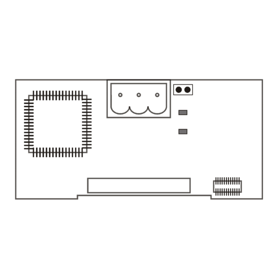
The MicroTech II LonWorks Communications Module is a printed circuit board that plugs into the MicroTech II Chiller Unit Controller. Figure 1 is an outline drawing of the printed circuit board. Figure 1. MicroTech II LonWorks Communications Module (Component Side) -
Page 5: Application
Building Automation System (BAS) on a LonWorks network. It is the interface adapter for the exchange of LonTalk variables between the network and the unit controller. The MicroTech II LonWorks Communications Module translates the LonWorks variables of the profile into the native information of the unit controller. -
Page 6: Service Pin
Flashes (1 second) when the node has no application program • Lights when there is a problem with the module Anomaly (Red) LonWorks Network Connector The P8 connector connects the MicroTech II LonWorks Communications Module to the LonWorks FTT-10A bus. Function No Connection FTT-10A FTT-10B 8-Pin Header The 8-pin header connects the unit controller to the communications module. -
Page 7: Lonmark Profile Software
LonMark Profile Software The MicroTech II LonWorks Communications Module software translates the Standard Network Variable Types (SNVTs) and Standard Network Configuration Parameter Types (SCPTs) in accordance with the LonMark profiles used on the LonWorks network into the variables and parameters used in the MicroTech II Chiller Unit Controller and conversely. -
Page 8: Installation
Installation The MicroTech II LonWorks Communications Module can be installed in the field or it can be installed in the factory. The module mounts on connector pins in the unit controller. Mounting The MicroTech II LonWorks Communications Module is included in a kit (Part number 350147401) and this manual. -
Page 9: Figure 4. Serial Card Slot Location On Unit Controller
Figure 4. Serial Card Slot Location on Unit Controller ® Air Conditioning Serial Card Slot Figure 5. Serial Card Slot Detail. 8-Pin Connector for LonWorks J1 9 Communications Module IM 735-0... -
Page 10: Figure 6. Network Cable Routing And Connections
Figure 6. Network Cable Routing and Connections Figure 7. Network Connection Detail Pi n A Pi n B N e tw o r k C a b l e IM 735-0... -
Page 11: Replacing An Existing Microtech Ii Lonworks Communications Module
13. Insert the network cable connector into the communications module. Unit Setup for Network Control To setup the MicroTech II Unit Controller for network control Disable the chiller. The chiller should not be operating while performing this setup. At the unit controller keypad, In the SET UNIT SPs (1) screen, set the setpoint “Source”... -
Page 12: Integration
Addressing and establishing communications with the unit, and Configuring the unit to the building. Connecting to the Network After you have installed the MicroTech II LonWorks Communications Module in the unit, you must connect it into the LonWorks network. Network Topology Each MicroTech II LonWorks Communications Module is equipped with an FTT-10A transceiver for network communications. -
Page 13: Figure 9. Combining Network Segments With A Repeater
A network segment is any part of the free topology network in which each conductor is electrically continuous. Each of the four diagrams is an illustration of a network segment. Some applications may require two or more segments; see “Free Topology Restrictions.”. If necessary, segments can be joined with FTT-10A-to-FTT-10A physical layer repeaters. -
Page 14: Physical Network
The maximum number of nodes per segment is 64. The maximum total bus length depends on the wire size (see “Qualified Cables” for details): Wire Size Maximum Cable Length 24 AWG 2952 ft (900 m) 22 AWG 4590 ft (1400 m) 16 AWG 8855 ft (2700 m) The maximum stub length is 9.8 ft (3 m). -
Page 15: Addressing And Establishing Communications
Default values may be changed via the network. See the appropriate operation manual for default values and keypad operation and see the MicroTech II Chiller Protocol Information for descriptions of the network variables. See Reference Documents for part numbers. -
Page 16: Service Information
Activate the Service Pin on the communications module to send the service message to the network. The service-pin message contains the Neuron ID and the program code identification of the node. If the MicroTech II Chiller LonWorks Communications Module still does not respond, replace the communications module. Replaceable Parts List Network Connection Plug Generic Replacement Parts If you lose this terminal block you can replace it with a standard block from a manufacturer.
Need help?
Do you have a question about the MicroTech II and is the answer not in the manual?
Questions and answers