Table of Contents
Advertisement
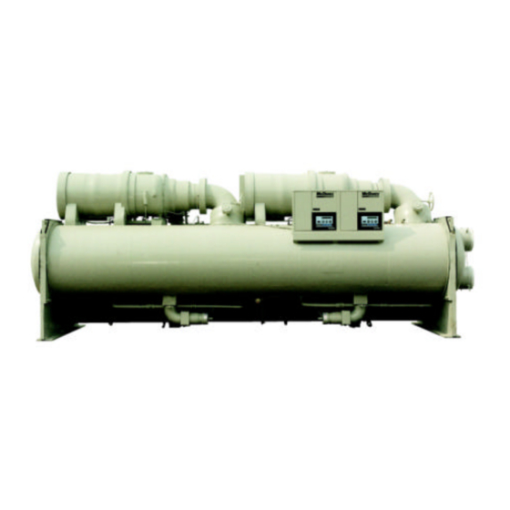
Centrifugal Compressor Water Chillers
THE DISTINCTION SERIES ™ ™
Model WDC, Dual Compressor, 160 to 2700 Tons (560 to 9500 kW)
Model WSC, Single Compressor, 80 to 1300 Tons (280 to 4550 kW)
HFC 134a, The Global Refrigerant of Choice
© 1998 McQuay International
Product Manual
PM WSCWDC
Group: Chiller
Date: October 1999
Supersedes: PM PEH/PFH-1
Advertisement
Table of Contents

Related Manuals for McQuay WDC


Summary of Contents for McQuay WDC
- Page 1 Centrifugal Compressor Water Chillers THE DISTINCTION SERIES ™ ™ Model WDC, Dual Compressor, 160 to 2700 Tons (560 to 9500 kW) Model WSC, Single Compressor, 80 to 1300 Tons (280 to 4550 kW) HFC 134a, The Global Refrigerant of Choice...
-
Page 2: Table Of Contents
"McQuay" is registered trademarks of McQuay International © 1996 McQuay International "Illustrations cover the general appearance of McQuay International products at the time of publication and we reserve the right to make changes in design and construction at anytime without notice" Product Manual PM WSC/WDC... -
Page 3: Introduction
McQuay will enter the 21 century with a new generation of centrifugal chillers. So advanced that they have been given a new model designation, WSC for single and WDC for dual compressor units. Their new name, the DISTINCTION SERIES™ , was deemed highly appropriate. -
Page 4: Design Advantages
The answer to this question is in the part load efficiency of the chiller-and no chiller can do as well as the McQuay Dual Centrifugal. These chillers excel when it comes to operating efficiency in the five percent to sixty percent capacity range-where 70 percent of the annual operating occur in most buildings. -
Page 5: Hfc-134A
The contaminant free, extended life lubricant used in McQuay chillers offers a means to gauge the health of your machine over the years. Through diagnostic analysis methods available for synthetic lubricants, preventative action can be taken should a potential problem show itself. - Page 6 Thus the need for a purge system is accompanied by the periodic release of refrigerant into the atmosphere, and attendant annual refrigerant cost. All McQuay centrifugal chillers use a positive pressure refrigerant. There is... • No absorption of impurities into the refrigerant circuit •...
-
Page 7: Compressor Design
80% of its running speed. While drawing locked rotor current the stresses on the motor are over six times that of full load. The McQuay compressors absolutely minimize this stress through the unique gear drive and light weight drive train that allows a 500 ton (1750 kW) compressor to reach running speed in less than three seconds. - Page 8 Thus, selection of McQuay chillers permits operation from 100% to 10% capacity (to 5% on WDC dual compressor chillers) without surging and at maximum efficiency, i.e. no hot gas bypass.
- Page 9 Again, this indicates that for a given speed requirement, a smaller diameter impeller in a compressor will operate at a higher rpm than a larger diameter impeller. Again: Stress ∝ ∝ Tip Speed Impellers with similar tip speeds have similar stress. Product Manual PM WSC/WDC...
- Page 10 Refrig. Circulated (lbs/min./ton) 3.08 3.00 2.78 Gas Flow (cfm/ton) 18.15 3.17 1.83 All McQuay centrifugal chillers use Tip Speed (ft./sec.) refrigerant HFC-134a. The machine design Ozone Depletion Potential (ODP) 0.02 0.00 0.05 characteristics of this refrigerant (and its predecessor, R-12) such as small moving parts, low mass, low inertia, quick spin-up and coast-down, and simplicity of design, have continuously proven themselves since the first chiller was introduced in 1962.
-
Page 11: Compact Design
HFC 134a Impeller Compared to HCFC 123 Impeller Left: Impeller from a McQuay single stage 300 ton (1050 kW) compressor; diameter = 6.3 in. (16 cm), weight = 3.0 lb (1.4 kg) Right: One of three impellers from a 300 ton HCFC-123 compressor; diameter = 26 in. (66 cm), weight = 27 lb. -
Page 12: Heat Exchangers
Since the McQuay chillers are positive pressure there is no need to change lubricant or filter on a regular basis. An annual oil check is recommended to evaluate the lubricant condition. -
Page 13: Surgegard
McQuay condensers are sized to hold the entire unit refrigerant charge when not more than 90% full at 90°F (32°C) ambient temperature. They are equipped with a tight-seating check valve at the hot gas inlet and a manual shutoff valve in the liquid outlet. -
Page 14: Factory Performance Test
Fast and trouble free startup and operation All WSC and WDC chillers are factory tested on ARI certified microprocessor based test stands. The test stand microprocessors interface with the chiller MicroTech controls, allowing monitoring of all aspects of the test stand and chiller operation. -
Page 15: Wdc Design Features
Standby redundancy for 80% of the cooling season The Redundancy Feature The McQuay Dual Centrifugal Chillers have two of everything connected to a common evaporator and condenser. Two compressors, two lubrication systems, two control systems, two starters. Should a failure occur to any component on a compressor system, the component can be removed or repaired without shutting down the other compressor;... -
Page 16: Part Load Efficiency
60% of design capacity. One compressor of a dual chiller operates with the full heat transfer surface of the entire unit, for example, one 500 ton (1,750 kW) compressor on a 1,000 ton (3,500 kW) Product Manual PM WSC/WDC... -
Page 17: Lower Installed Costs
Opens many options for multiple chiller plants WDC Chiller Controls Each model WDC dual compressor chiller comes complete with two compressor-dedicated factory mounted and wired MicroTech control panels. Individual control panels allow the monitoring of each compressor independently from the other. Elapsed time, number of starts, percent RLA ; are all monitored separately by each MicroTech control panel. - Page 18 The majority of comfort cooling systems operate at 60% or less of building design tons for most of the year. A great number of those operating hours occur between 50% and 60% design cooling capacity. For that reason, the Model WDC chiller was designed to produce up to 60% unit capacity with a single operating compressor, efficiently and reliably.
-
Page 19: Control Features
Control Features All McQuay Chillers Feature MicroTech Controls McQuay has incorporated the latest microprocessor technology into the MicroTech control system to give you the ultimate in centrifugal chiller control. The control includes many energy-saving features not found in any other microprocessor system on the market today. MicroTech’s innovative design will keep your chiller running efficiently. - Page 20 MicroTech increases chiller operating economy Many standard features have been incorporated into MicroTech in order to improve the operating economy of McQuay centrifugal chillers. In addition to replacing normal relay logic circuits, we’ve enhanced MicroTech’s energy saving capabilities with the following features: •...
- Page 21 Lead-lag and load balance. The standard MicroTech is capable of compressor lead-lag decisions and balancing compressor loads between two McQuay compressors, whether on separate chillers or mounted on a WDC Dual Compressor unit. This feature assures optimum efficiency under any load condition. •...
-
Page 22: Building Management Systems
Building Management Systems. Here are just a few of the 220 points on a WDC chiller that are available remotely through one simple, low cost twisted-pair interface. - Page 23 Temperature monitoring of primary and secondary chilled water loop, outside air temperature and tower water supply and return temperature. • Central on/off control point for all machines. • Optimized morning start-up to insure full cooling at a specified time. Product Manual PM WSC/WDC...
- Page 24 If there is still some load on the chilled water, its temperature will rise until it reaches the cycle-on temperature setting. At this point the compressor will initiate its start cycle and commence operation. Product Manual PM WSC/WDC...
-
Page 25: Sound
Sound Levels -- One Of The Quietest Centrifugal Chillers In The Industry McQuay centrifugal chillers are one of the quietest units available in the marketplace. It is easy to make this type of claim!! For us, it is just as easy to support!! Unique!! --- Quiet full load sound levels and QUIETER part load sound levels. -
Page 26: Unit Selection
Integrated Part Load Value (IPLV) or Non-Standard Part Load Value (NPLV) As part of the ARI certification program, ARI has approved the McQuay computer selection program used to select and rate chillers. The certified computer program version number and issue date for all manufacturers is listed in the ARI Directory of Certified Applied Air-Conditioning Products published biannually. - Page 27 The ARI test tolerance, per ARI Standard 550/590-98, for capacity (tons), power input per ton (kW/ton), and heat balance is: 1500 − Tolerance 10 5 0 07 x FL DTFLx Where: FL = Full Load DTFL = Chilled Water Delta-T at Full Load Product Manual PM WSC/WDC...
-
Page 28: Chiller Identification
To provide a wide range of components to match job requirements of capacity, efficiency and competitive initial cost, McQuay WSC and WDC centrifugal chillers are selected by computer and identified by their components. The variations of compressor, impeller, gear ratio, evaporator and condenser tube surface and configuration provide over 1,000,000 combinations of standard components within the range of 70 to 2,500 tons. -
Page 29: Physical Data And Weights
Refrigerant side design pressure is 200 psi (1380 kPa), water side design is 150 psi (1034 kPa). Pumpdown To facilitate non-routine compressor service, all McQuay centrifugal chillers are designed to permit pumpdown and isolation of the entire refrigerant charge in the unit’s condenser. Dual compressor units and single compressor units equipped with the optional suction shutoff valve can also be pumped down into the evaporator. -
Page 30: Evaporator
Actual charge for a specific selection can vary with tube count and can be obtained from MS-85 Selection Program. The program will not allow a selection where the unit charge exceeds the condenser pumpdown capacity. Product Manual PM WSC/WDC... -
Page 31: Compressor
The discharge from more than one relief valve may be run into a common header, the area of which shall not be less than the sum of the areas of the connected pipes. For further details, refer to ASHRAE Standard 15. The common header can be calculated by the formula: Product Manual PM WSC/WDC... -
Page 32: Pumpout Units
Standard 15 for sizing data. Pumpout Units Although McQuay chillers can pump the entire refrigerant charge into the condenser and valve it off, there are occasions when pumpout units are required due purely to specification requirements or unusual job considerations. The McQuay Model LSA units consist of an ASME storage tank, a top mounted air-cooled condensing unit with a 1 HP compressor to provide motive power, and necessary valves and fittings to constitute a complete system. -
Page 33: Dimensions
4. Allow the length of the tubes plus two feet on one end for tube removal. The last two numbers in the vessel code are the tube length in feet. 5. Mounting holes are 1 1/8 in. (2.9 cm) diameter. 6. Approximate thickness of waffle pad when compressed: ¼ in. (.63 cm). Product Manual PM WSC/WDC... - Page 34 (1219) (1016) 2612 2612 (4293) (4166) (4293) (2184) (1219) (1753) (965) (533) (3759) (3683) (1219) (1016) 3012 2612 (4445) (4242) (4445) (2286) (1346) (1702) (1041) (533) (3759) (3683) (1646) (1143) Note: See notes on page 33. Product Manual PM WSC/WDC...
- Page 35 (1880) (1676) 3612 3012 (4445) (4267) (4445) (2388) (1880) (1778) (1041) (864) (3759) (3683) (1879) (1676) 3612 3612 (4445) (4267) (4445) (2667) (2032) (1778) (1168) (965) (3759) (3683) (2032) (1829) Note: See notes on page 33. Product Manual PM WSC/WDC...
- Page 36 2337) (2134) 4812 4212 (4597) (4445) (4597) (2692) (2489) (1753) (1168) 1067) (3759) (3683) 2489) (2286) 4812 4812 (4597) (4445) (4597) (2692) (2642) (1778) (1168) (1168) (3683) (3683) (2642) (2438) Note: See notes on page 33. Product Manual PM WSC/WDC...
- Page 37 WDC 048/050, 180 to 320 tons VESSEL CODE OVERALL LENGTH OVERALL CONNECTIONS OVERALL CENTER OF GRAVITY FOOTPRINT 1&3 HEAD CONN WIDTH W/O EVAP COND HEIGHT EVAP COND PASS PASS BOTH ENDS STARTER PASS PASS E1812 C1612 (4298) (4134) (4298) (1883)
- Page 38 WDC 063, 320 to 600 tons VESSEL CODE OVERALL LENGTH OVERALL CONNECTIONS OVERALL CENTER OF GRAVITY FOOTPRINT 1&3 HEAD CONN WIDTH W/O EVAP COND HEIGHT EVAP COND PASS PASS .BOTH ENDS STARTER PASS PASS E2416 C2416 (5544) (5426) (5544) (2032)
- Page 39 WDC 079, 600 to 700 tons VESSEL CODE OVERALL LENGTH OVERALL CONNECTIONS OVERALL CENTER OF GRAVITY FOOTPRINT 1&3 HEAD CONN WIDTH W/O EVAP COND HEIGHT EVAP COND PASS PASS BOTH ENDS STARTER PASS PASS E3016 C3016 (5620) (5442) (5620) (2407)
- Page 40 WDC 087, 700 to 1200 tons VESSEL CODE OVERALL LENGTH OVERALL CONNECTIONS OVERALL CENTER OF GRAVITY FOOTPRINT 1&3 HEAD CONN WIDTH W/O EVAP COND HEIGHT EVAP COND PASS PASS .BOTH ENDS STARTER PASS PASS E3016 C3016 (5620) (5442) (5620) (2410)
- Page 41 WDC 100, 1200 to 1700 tons VESSEL CODE OVERALL LENGTH OVERALL CONNECTIONS OVERALL CENTER OF GRAVITY FOOTPRINT 1&3 HEAD CONN WIDTH W/O EVAP COND HEIGHT W/O STARTER EVAP COND PASS PASS BOTH ENDS STARTER PASS PASS E3616 C3616 (5692) (5528)
- Page 42 WDC 126, 1600 to 2700 tons VESSEL CODE OVERALL LENGTH OVERALL CONNECTIONS OVERALL CENTER OF GRAVITY FOOTPRINT 1&3 HEAD CONN WIDTH W/O EVAP COND HEIGHT EVAP COND PASS PASS BOTH ENDS STARTER PASS PASS E3616 C3616 (5692) (5528) (5692) (2652)
-
Page 43: Marine Water Boxes
Some condensers with flanges may have staggered connections due to flange interference. Consult factory. When built with flange connections instead of victaulic, the distance from the vertical centerline to the flange face is 0.5 inches more than shown with victaulic (dimension D). Product Manual PM WSC/WDC... -
Page 44: Weights
29298 (13290) 34024 (15433) 30498 (13834) 35224 (15978) WSC126 4812 / 4212 WSC 100/126 32024 (14526) 37623 (17066) 33224 (15070) 38823 (17610) WSC126 4812 / 4812 WSC 100/126 35016 (15883) 41817 (18968) 36216 (16427) 43017 (19513) Product Manual PM WSC/WDC... - Page 45 74745 (33904) WDC126 4820 / 4820 F2480480 65964 (29921) 77698 (35243) 68364 (31009) 80098 (36332) WDC126 4824 / 4824 F2484484 75831 (34396) 89410 (40556) 78231 (35485) 91810 (41644) Note: Unit not available with factory mounted starters. Product Manual PM WSC/WDC...
-
Page 46: Pumpout Units
I in. liquid receiver valves must be piped per ANSI 15 for each storage tank. Refer to evaporator physical data on page 30 for unit refrigerant charge. Use certified drawings from local sales office for more dimensional detail and for construction. Product Manual PM WSC/WDC... -
Page 47: Electrical Data
An interposing relay may be required on remote mounted starter applications when the length of the conductors run between the chiller and starter is excessive. Note: On WDC dual compressor units, dual power leads are standard, requiring separate power leads properly sized and protected to each compressor starter. Separate disconnects must be used. - Page 48 Locked Rotor Amps 4304 3665 3839 4013 2736 Power Factor Max kW Locked Rotor Amps Power Factor Max kW Locked Rotor Amps 8069 8406 8069 8452 8836 4778 3737 3914 4092 3131 Power Factor (Continued next page) Product Manual PM WSC/WDC...
- Page 49 1498 1585 1638 1272 Power Factor Max kW Locked Rotor Amps Power Factor Max kW Locked Rotor Amps 2740 2027 1577 1666 1735 1423 Power Factor Max kW Locked Rotor Amps Power Factor (Continued next page) Product Manual PM WSC/WDC...
- Page 50 Power Factor Max kW Locked Rotor Amps 6151 4676 4933 5126 4280 Power Factor Max kW Locked Rotor Amps Power Factor Max kW Locked Rotor Amps 7143 5743 6059 6297 5541 Power Factor (Continued next page) Product Manual PM WSC/WDC...
-
Page 51: Field Wiring
Locked Rotor Amps 8522 8125 6898 6532 6003 Power Factor Field Wiring Model WSC/WDC centrifugal chillers require field connected power and interlock wiring to complete their integration into an operating system. Typical Field Connection Diagram, WSC Unit Product Manual PM WSC/WDC... -
Page 52: Control Power
If starters are free standing then field wiring between the starter and the control panel is required. Minimum wire size for 115 VAC is 12GA for maximum length of 50 feet. If greater than 50 feet, refer to McQuay for recommended wire size minimum. -
Page 53: Motor Starters
Motor Starters McQuay has a wide variety of starter types and options to fit virtually all applications. The specifics of the final selection of size and enclosure are covered in the product manual PM Starters. Please consult the local McQuay sales office or this manual for starter details. This section contains a general overview only. - Page 54 Additional Options for Medium Voltage Starters Certifications and Approvals • UL certification for full voltage starters • UL certification for reduced voltage starters • CSA certification for full voltage starters • CSA certification for reduced voltage starters Product Manual PM WSC/WDC...
- Page 55 • NEMA 4 -- Rain tight construction * • NEMA 4/4X with stainless steel construction for both non combustion and combustion use * • NEMA 12 -- Dust tight construction * * Low voltage starters only Product Manual PM WSC/WDC...
-
Page 56: Application Considerations
Pumps Model WSC and WDC chiller compressor motors operate at 3600 rpm at 60 Hz (3000 rpm at 50 Hz). To avoid the possibility of objectionable harmonics in the system piping, the use of 3600 (3000) rpm system pumps should be avoided. -
Page 57: Oil Coolers
Accessories must be installed as shown in the following piping diagrams. WDC 063, 079, 087, 100 and 126 dual compressor units are equipped as above but the water piping for the two oil coolers cooling is factory piped to a common connection at the tube sheet. -
Page 58: Machine Room Ventilation
On the other hand, open motors circulate equipment room air across themselves for cooling and reject the heat to the equipment room. McQuay chillers have hermetic motors and DO NOT require additional ventilation. -
Page 59: Thermal Storage
Second, the water velocity in the vessels must remain between 3 and 10 fps (0.91 and 3.0 m/sec). Below 3 fps (0.91 m/sec), laminar flow occurs which reduces heat transfer. Above 10 fps (3.0 m/sec), excessively high pressure drops and tube erosion occur. These flow limits can be determined from the McQuay MS-85 selection program. -
Page 60: Free Cooling
McQuay chillers are well suited to this application and, as with all chillers, attention must be paid to the system design, particularly to the switching from the economizer (free cooling) cycle to normal compressor operation. -
Page 61: Options And Accessories
Includes the modem required for remote monitoring one or more units. Requires Monitor software. Monitor software Required for installation in a PC to complete remote monitoring capability. Chiller System Controller Details described in the Control Section of this manual. Product Manual PM WSC/WDC... - Page 62 Witness performance test The standard full load run test is performed in the presence of the customer under the supervision of a McQuay engineer, includes compilation of the test data. Travel and local expenses are not included. Certified performance test The standard run test is performed under the supervision of a McQuay engineer, data is compiled and certified.
-
Page 63: Specifications
1.5 DELIVERY AND HANDLING Chillers shall be delivered to the job site completely assembled and charged with refrigerant and oil. Comply with the manufacturer’s instructions for rigging and transporting units. Leave protective covers in place until installation. Product Manual PM WSC/WDC... - Page 64 ARI Standard 575-87. Data shall be in dB. Data shall be the highest levels recorded at all load points. Test shall be in accordance with ARI Standard 575. Octave Band 1000 2000 4000 8000 Product Manual PM WSC/WDC...
- Page 65 The water sides shall be designed for a minimum of 150 psig or as specified elsewhere. Vents and drains shall be provided. Chilled water minimum refrigerant temperature shall be 33°F. Product Manual PM WSC/WDC...
- Page 66 The main motor starter is to be furnished by the chiller manufacturer and shipped loose for floor mounting and field wiring to the chiller package. It shall be free-standing with NEMA-1 enclosure designed for top entry and bottom exit and with front access. Product Manual PM WSC/WDC...
- Page 67 The starters shall be equipped with redundant motor control relays (MCR) with coils in parallel. The relays interconnect the starters with the unit control panels and Product Manual PM WSC/WDC...
- Page 68 Each starter shall be equipped with a line-to-115 VAC control transformer, fused in both the primary and secondary, to supply power to the control panels, oil heaters and oil pumps. Each starter shall include the following protective devices: a) Phase failure and reversal protection Product Manual PM WSC/WDC...
- Page 69 High motor temperature, low motor current Surge-high suction superheat Starter fault, no starter transition k) Vanes open during start sequence Sensor failure, specific to sensor Controller shall hold leaving chilled water temperature to within 0.2°F. without hunting, droop, or overshooting. Product Manual PM WSC/WDC...
- Page 70 A dedicated condensing unit shall be provided with the purge system to provide a cooling source whether or not the chiller is running. The condensing unit shall provide a low purge coil temperature to result in a maximum loss of 0.1 pounds of refrigerant per pound of purged air. Product Manual PM WSC/WDC...
- Page 71 During the period of start-up, the Start-up Technician shall instruct the Owner’s representative in proper care and operation of the unit. Product Manual PM WSC/WDC...
- Page 72 (five) years from date of equipment start or 18 months from shipment whichever occurs first. The warranty shall include parts and labor costs for the repair or replacement of defects in material or workmanship. The refrigerant charge shall be warranted against contamination from a motor burnout for five years. Product Manual PM WSC/WDC...
- Page 73 Unit shall have two single-stage hermetic centrifugal compressors. Casing design shall ensure major wearing parts, main bearings and thrust bearings are accessible for maintenance and replacement. Lubrication system shall protect machine during coast down resulting from a loss of power. Product Manual PM WSC/WDC...
- Page 74 A self-metering and adjustable thermal expansion valve shall control refrigerant flow to the evaporator. Fixed orifice devices or float controls with hot gas bypass are not acceptable because of inefficient control at low load conditions. The liquid line shall have a moisture indicating sight glass. Product Manual PM WSC/WDC...
- Page 75 For air-cooled motors the chiller manufacturer shall be responsible for providing the cooling of the refrigeration machinery room. The sensible cooling load shall be based on the total heat rejection to the atmosphere from tow refrigeration units. Product Manual PM WSC/WDC...
- Page 76 The starters shall be equipped with redundant motor control relays (MCR) with coils in parallel. The relays interconnect the starters with the unit control panels and directly operate the main motor contactors. The MCRs shall constitute the only means of energizing the motor contacts. Product Manual PM WSC/WDC...
- Page 77 Oil feed and sump temperatures g) Oil pump discharge and oil differential pressure h) Motor amps and amps as a percent of rated load amps Hours of operation and number of starts, time of last start and stop Product Manual PM WSC/WDC...
- Page 78 The microprocessor shall be capable of communicating to other units or a PC using a twisted pair communication interface of RS-232 (100 feet) or RS-422/485 (5000 feet) or with a 9600 baud modem. Product Manual PM WSC/WDC...
- Page 79 Waffle type vibration pads for field mounting under unit feet. PART 3 — EXECUTION 3.1 INSTALLATION Install per manufacturer’s requirements, shop drawings, and Contract Documents. Product Manual PM WSC/WDC...
- Page 80 During the period of start-up, The Start-up Technician shall instruct the Owner’s representative in proper care and operation of the unit. Product Manual PM WSC/WDC...
- Page 81 Product Manual PM WSC/WDC...
- Page 82 Product Manual PM WSC/WDC...
- Page 84 Post Office Box 2510, Staunton, Virginia USA (540) 248-0711 www.mcquay.com...
Need help?
Do you have a question about the WDC and is the answer not in the manual?
Questions and answers
What is daikin WDC 126 Refrigerant flowrate?