McQuay MicroTech Installation & Maintenance Data
Open protocol master panel
Hide thumbs
Also See for MicroTech:
- Installation and maintenance data (11 pages) ,
- Installation and maintenance data (44 pages)

Related Manuals for McQuay MicroTech


Summary of Contents for McQuay MicroTech
- Page 1 Installation & Maintenance Data IM 474-3 Group: Controls Part Number: 573897Y Date: June 1996 MicroTech ® Open Protocol Master Panel Open Protocol Master MicroTech © 1996 McQuay International...
-
Page 2: Table Of Contents
MCB Replacement ..........................24 Parts List............................. 24 McQuay, AAF, and MicroTech are registered trademarks of McQuay International. MicroTech 2000, Monitor, and Open Protocol are trademarks of McQuay International. All other trademarks are the property of their respective owners. IM 474-3... -
Page 3: Introduction
1. The MicroTech Absorption Gateway (MAG) is an interface to McQuay absorption chillers, which use Sanyo controllers. 2. The MicroTech Communications Gateway (MCG) is an interface to McQuay water source heat pumps, which use MicroTech 2000™ controllers. When there are only MicroTech 2000 controllers, an MCG can substitute for an OPM Panel. -
Page 4: Applying The Opm Panel
When to Use an OPM Panel Use an OPM to The OPM Panel should be used when there are two or more MicroTech controllers that need to be provide a single-point interfaced with a BAS by means of a single-point connection. (The maximum number of unit connection from a controllers per OPM depends on the BAS.) For example, the OPM Panel could combine a McQuay... -
Page 5: Alternatives To The Opm Panel
• MCG and MicroTech 2000 controllers only If a BAS will be connected to a series of MicroTech 2000 controllers (and no MicroTech controllers), the MicroTech Communications Gateway (MCG) can substitute for an OPM. In this instance, an OPM is not required. (Since the MCG is considered a MicroTech controller and MicroTech 2000 controllers are not, this is just a specific “only-one-controller”... - Page 6 discourage this practice. Instead, we recommend that the LWC be given a separate, dedicated connection to the BAS. The reason is that the BAS must coordinate loop water alarm control for the heat pumps regardless of how the LWC is connected. By providing a separate connection to the BAS, the response time can be speeded up significantly, reducing the risk of heat pump alarms, mechanical safety trips, or even equipment damage.
-
Page 7: General Description
The MicroTech Open Protocol Master (OPM) Panel is a microprocessor-based controller that allows other MicroTech controllers to interface with a third-party building automation system (BAS). The OPM Panel is used when single-point entry is required to communicate with two or more MicroTech controllers. An IBM® compatible computer containing MicroTech Open Protocol Monitor™... -
Page 8: Microprocessor Control Board
“PC Connection” on page 13. Note: Remote connection with a BAS via modem is not supported. Port B: Port B is for MicroTech network communications using RS-485. The communications rate is 9600 baud. For more information, see “Network Communications” on page 11. -
Page 9: Software Id
Program inactive (checksums corrupt) or no power to MCB Software ID MicroTech OPM software is factory installed and tested in each panel prior to shipment. The software is identified by a program code (also referred to as the “Ident”). The program code is encoded in the controller’s memory and is available for display on a PC equipped with Open Protocol Monitor... -
Page 10: Installation
Installation Panel Location and Mounting The OPM Panel is suitable for indoor use only. Table 4 lists the allowable temperature and humidity ranges. Locate the panel at a convenient height, and allow adequate clearance for the door swing. Mount the panel to the wall with screws or bolts. It weighs approximately 30 pounds (14 kg). Four ¼- inch openings are provided at the corners of the panel. -
Page 11: Field Wiring
About MicroTech Network Architecture All controllers in a MicroTech network are assigned a level: level 1, level 2, or level 3. All networks must have one level-1 controller to coordinate communications. Multiple level-2 controllers connect to the level-1 controller with a communications trunk. A trunk is defined as an isolated section of the daisy-chained network wiring. - Page 12 Figure 4. Typical Field Wiring Schematic 115 Vac power Neutral B– Port B Port A A– See notes 1 & 2 3rd-party BAS Legend Notes: 1. Twisted, shielded pair cable must meet the following minimum requirements: 300 V, 60°C, 20 AWG, polyethylene Field wiring terminal insulated, with a PVC outer jacket and drain wire (Belden Field wiring: discrete...
-
Page 13: Pc Connection
User’s Manual for more information on changing the OPM’s port configurations. Direct Connection An RS-232 communications cable kit that allows a PC to be directly connected to any MicroTech controller is available from McQuay International. The part number is 0057186802. The cable has a female DB-9 connector for connection to the PC’s 9-pin serial port. - Page 14 Note: A factory-assembled cable that meets this specification is provided with the PC Communications Cable Kit, which is available from McQuay International. This cable has a DB-9 connector and an AMP plug. An AMP-to-Phoenix plug adapter is included. The kit part number is 0057186802.
-
Page 15: Network Commissioning
The purpose of network commissioning is to establish and verify communications between the OPM (or its substitute) and its networked MicroTech unit or auxiliary controllers. (It is not to establish and verify unit operation.) The network commissioning procedure is similar for all level-1 panels used in an Open Protocol environment when two or more unit controllers are included in the network. - Page 16 After changing a hex switch setting, power to the MCB must be cycled to set the new address into memory. In the OPM and most other MicroTech panels, you can do this by opening and then closing circuit breaker CB1. In the unit controllers, this can be done in a variety of ways. Refer to the individual installation manuals for more information on cycling power to the unit controller MCBs.
-
Page 17: Opm Controller Setup
Phoenix adapter first (see Figure 7 on page 14). To use the PC, it must have the Open Protocol Monitor software loaded. See Chapter 1, “Setting Up the Monitor Program,” in the MicroTech Open Protocol Monitor Software User’s Manual for information on installing the software. -
Page 18: Connecting The Level-2 Trunk
Program Checksum. The number of level-2 slaves must be set to match the quantity of MicroTech unit or auxiliary controllers connected to the network. If the number entered into the Monitor software is less than the actual quantity of controllers in the network, you will not know if all the controllers are communicating properly with the OPM Panel. - Page 19 Go to the last controller on one end of the daisy-chain and place a jumper across the “+” and “–” terminals. Then go to the last controller on the other end of the daisy-chain and use an ohmmeter to test for continuity across the “+” and “–” terminals. Remove the jumper and repeat this step for the other two conductor pairs: “+”...
- Page 20 PC can connect to the OPM through port A with the communications password shown on the Monitor screen. The BAS should use this same password. If the BAS cannot connect using this password, there is likely a problem on the BAS side, not the McQuay side. Table 7. Port B Voltages...
- Page 21 Figure 9. Phoenix Connector Terminal Configuration Plug (top view) Socket – Figure 10. AMP Connector Terminal Configuration FUSE 1 PORT A PORT B COMMUNICATIONS [FUSE: BUSSMAN MCR-1/4] Figure 11. IDC Connector Terminal Configuration Bottom View IM 474-3...
-
Page 22: Service Information
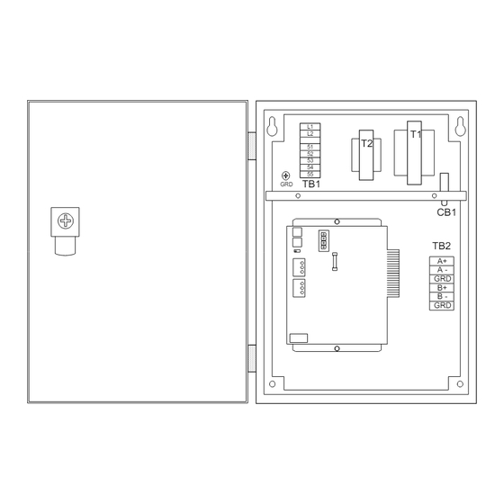
Service Information Wiring Diagram The following wiring diagram is identical to the one in the OPM Panel. It is reproduced here for your convenience. The legend is shown in Table 8. Table 8. OPM Panel Schematic Legend Component designation Description CB1 ....... -
Page 23: Test Procedures
Test Procedures A listing of MicroTech related part numbers is included on page 24. If the MCB must be replaced, see page 24. LED Diagnostics The MCB LED indications can aid in controller diagnostics. If the status LEDs do not operate normally as described in the “Component Data”... -
Page 24: Mcb Replacement
The best way to accomplish these checks is to perform the start-up procedures in the “Network Commissioning” section of this manual. If these procedures have been performed and the problem persists, obtain factory service. MCB Replacement If an MCB board is defective and must be replaced, the proper controller software must be loaded into the replacement MCB.
Need help?
Do you have a question about the MicroTech and is the answer not in the manual?
Questions and answers