Vega VEGABAR 86 Operating Instructions Manual
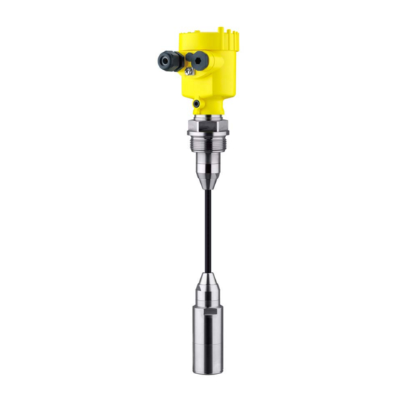
Submersible pressure transmitter with ceramic measuring cell
Hide thumbs
Also See for VEGABAR 86:
- Operating instructions manual (92 pages) ,
- Quick setup manual (24 pages) ,
- Quick setup manual (20 pages)

Subscribe to Our Youtube Channel
Related Manuals for Vega VEGABAR 86


Summary of Contents for Vega VEGABAR 86
- Page 1 Operating Instructions Submersible pressure transmitter with ceramic measuring cell VEGABAR 86 Modbus and Levelmaster protocol Document ID: 46296...
-
Page 2: Table Of Contents
Connect the PC ......................38 Parameter adjustment with PACTware ................39 Set instrument address ....................40 Saving the parameterisation data ................... 41 Diagnosis, asset management and service ................ 42 Maintenance ........................42 Diagnosis memory ......................42 VEGABAR 86 • Modbus and Levelmaster protocol... - Page 3 10.10 Industrial property rights ....................83 10.11 Trademark ........................83 Safety instructions for Ex areas Take note of the Ex specific safety instructions for Ex applications. These instructions are attached as documents to each instrument with Ex approval and are part of the operating instructions. Editing status: 2019-03-11 VEGABAR 86 • Modbus and Levelmaster protocol...
-
Page 4: About This Document
Symbols used Document ID This symbol on the front page of this instruction refers to the Docu- ment ID. By entering the Document ID on www.vega.com you will reach the document download. Information, tip, note This symbol indicates helpful additional information. -
Page 5: For Your Safety
During work on and with the device, the required personal protective equipment must always be worn. Appropriate use Model VEGABAR 86 is a pressure transmitter for level and gauge measurement. You can find detailed information about the area of application in chapter "Product description". Operational reliability is ensured only if the instrument is properly used according to the specifications in the operating instructions manual as well as possible supplementary instructions. -
Page 6: Eu Conformity
Protection of the environment is one of our most important duties. That is why we have introduced an environment management system with the goal of continuously improving company environmental pro- tection. The environment management system is certified according to DIN EN ISO 14001. VEGABAR 86 • Modbus and Levelmaster protocol... - Page 7 2 For your safety Please help us fulfil this obligation by observing the environmental instructions in this manual: • Chapter "Packaging, transport and storage" • Chapter "Disposal" VEGABAR 86 • Modbus and Levelmaster protocol...
-
Page 8: Product Description
Power supply and signal output, electronics Technical data Order number Serial number of the instrument QR code Symbol of the device protection class ID numbers, instrument documentation 10 Reminder to observe the instrument documentation VEGABAR 86 • Modbus and Levelmaster protocol... -
Page 9: Principle Of Operation
Alternatively, you can access the data via your smartphone: • Download the VEGA Tools app from the "Apple App Store" or the "Google Play Store" • Scan the Data Matrix code on the type label of the instrument or •... - Page 10 3 Product description Fig. 3: Level measurement with VEGABAR 86 Measuring system pres- The sensor element is the CERTEC measuring cell with robust ® sure ceramic diaphragm. The process pressure deflects the ceramic diaphragm and causes a capacitance change in the measuring cell. This capacitance change is converted into an electrical signal and outputted as measured value via the output signal.
-
Page 11: Packaging, Transport And Storage
Unless otherwise indicated, the packages must be stored only under the following conditions: • Not in the open • Dry and dust free VEGABAR 86 • Modbus and Levelmaster protocol... -
Page 12: Accessories And Replacement Parts
USB interface of a PC. Slave sensors Slave sensors of VEGABAR series 80 enable in conjunction with VEGABAR 86 an electronic differential pressure measurement. VEGADIS 81 The VEGADIS 81 is an external display and adjustment unit for VEGA plics sensors. ® VEGADIS adapter The VEGADIS adapter is an accessory part for sensors with double chamber housings. -
Page 13: Mounting
You can find detailed information on the process conditions in chapter "Technical data" as well as on the type label. Transport and mounting Depending on the transmitter, the VEGABAR 86 is supplied with a protection protective cap or a transport and mounting protection. Fig. 5: VEGABAR 86, transport and mounting protection... - Page 14 Make sure that the upper temperature limits stated in chapter "Technical data" for the environment of the electronics hous- ing and connection cable are not exceeded. Fig. 6: Temperature ranges Process temperature Ambient temperature VEGABAR 86 • Modbus and Levelmaster protocol...
-
Page 15: Ventilation And Pressure Compensation
Level measurement Measurement setup Keep the following in mind when setting up the measuring system: • Do not mount the instrument close to the filling stream or emptying area • Mount the instrument so that it is protected against pressure shocks from the stirrer VEGABAR 86 • Modbus and Levelmaster protocol... -
Page 16: External Housing
4 Mounting External housing Configuration Fig. 8: Arrangement measurement loop, external housing Sensor Connection cable sensor, external housing External housing Signal cable VEGABAR 86 • Modbus and Levelmaster protocol... -
Page 17: Connecting To Power Supply And Bus System
Prior to setup you have to replace these protective caps with ap- proved cable glands or close the openings with suitable blind plugs. VEGABAR 86 • Modbus and Levelmaster protocol... -
Page 18: Connecting
Fig. 9: Connection steps 5 and 6 5. Insert the wire ends into the terminals according to the wiring plan Information: Solid cores as well as flexible cores with wire end sleeves are insert- ed directly into the terminal openings. In case of flexible cores without end sleeves, press the terminal from above with a small screwdriver, VEGABAR 86 • Modbus and Levelmaster protocol... -
Page 19: Wiring Plan
When inserting the terminal block again, you should hear it snap in. Wiring plan Overview Fig. 10: Position of connection compartment (Modbus electronics) and electron- ics compartment (sensor electronics) Connection compartment Electronics compartment VEGABAR 86 • Modbus and Levelmaster protocol... - Page 20 Slide switch for integrated termination resistor (120 Ω) Modbus signal Voltage supply Terminal Function Polarity Voltage supply Voltage supply Modbus signal D0 Modbus signal D1 Function ground when installing ac- cording to CSA (Canadian Standards Association) VEGABAR 86 • Modbus and Levelmaster protocol...
-
Page 21: External Housing
Breather capillaries Electronics and connec- tion compartment for power supply 4...20mA 6 7 8 Fig. 14: Electronics and connection compartment Electronics module Cable gland for voltage supply Cable gland for connection cable, transmitter VEGABAR 86 • Modbus and Levelmaster protocol... -
Page 22: Switch-On Phase
Output signal at instruments with current output jumps to the set fault current Then the actual measured value is output to the signal cable. The value takes into account settings that have already been carried out, e.g. default setting. VEGABAR 86 • Modbus and Levelmaster protocol... -
Page 23: Set Up The Sensor With The Display And Adjustment Module
The display and adjustment module is powered by the sensor, an ad- ditional connection is not necessary. Fig. 16: Insertion of the display and adjustment module Note: If you intend to retrofit the instrument with a display and adjustment module for continuous measured value indication, a higher lid with an inspection glass is required. VEGABAR 86 • Modbus and Levelmaster protocol... -
Page 24: Adjustment System
The pen oper- ates the four keys of the display and adjustment module right through the closed lid (with inspection window) of the sensor housing. VEGABAR 86 • Modbus and Levelmaster protocol... -
Page 25: Measured Value Indication
With the "OK" key you move (during the initial setup of the instrument) to the selection menu "Language". Selection language In this menu item, you can select the national language for further parameterization. VEGABAR 86 • Modbus and Levelmaster protocol... -
Page 26: Parameter Adjustment - Quick Setup
Setup: Settings, e.g., for measurement loop name, application, units, position correction, adjustment, signal output Display: Settings, e.g., for language, measured value display, lighting Diagnosis: Information, e.g. on instrument status, pointer, measure- ment reliability, simulation VEGABAR 86 • Modbus and Levelmaster protocol... - Page 27 In this menu item you activate/deactivate the slave sensor for elec- tronic differential pressure and select the application. VEGABAR 86 can be used for process pressure and level measure- ment. The setting in the delivery status is process pressure measure- ment. The mode can be changed in this adjustment menu.
- Page 28 Parameterization example VEGABAR 86 always measures pressure independently of the pro- cess variable selected in the menu item "Application". To output the selected process variable correctly, an allocation of the output signal to 0 % and 100 % must be carried out (adjustment).
- Page 29 2. Edit the percentage value with [OK] and set the cursor to the requested position with [->]. 3. Set the requested percentage value (e.g. 10 %) with [+] and save with [OK]. The cursor jumps now to the pressure value. VEGABAR 86 • Modbus and Levelmaster protocol...
- Page 30 - and the indication or output of the volume is required. Corresponding linearization curves are preprogrammed for these vessels. They represent the correlation between the level per- centage and vessel volume. The linearization applies to the measured value indication and the current output. With flow measurement and selection "Linear" display and output (percentage/current) are linear to "Differential pressure". This can be used, for example, to feed a flow computer. VEGABAR 86 • Modbus and Levelmaster protocol...
- Page 31 • German • English • French • Spanish • Russian • Italian • Dutch • Portuguese • Japanese The device assumes an approximately constant temperature and static pressure and converts the differential pressure into the flow rate via the characteristic curve extracted by root. VEGABAR 86 • Modbus and Levelmaster protocol...
- Page 32 Polish • Czech • Turkish In delivery status, the VEGABAR 86 is set to English. Display - Displayed value In this menu item, you define which measured value is displayed. 1 and 2 The setting in the delivery status for the display value is "Lin. percent". Display - Display format...
- Page 33 In this menu item, you adjust the internal clock of the sensor. There is Additional settings - Date/ Time no adjustment for summer/winter (daylight saving) time. Additional settings - After a reset, certain parameter adjustments made by the user are Reset reset. VEGABAR 86 • Modbus and Levelmaster protocol...
- Page 34 Displayed value 2 Ceramic measuring cell: Measuring cell temperature in °C Metallic measuring cell: Electronics temperature in °C Display format 1 and 2 Number of positions after the decimal point, automatically Backlight Switched on VEGABAR 86 • Modbus and Levelmaster protocol...
- Page 35 If the data do not match, a fault message is outputted or the function is blocked. The data are saved only after release. VEGABAR 86 • Modbus and Levelmaster protocol...
- Page 36 PC. Info - Sensor character- In this menu item, the features of the sensor such as approval, pro- istics cess fitting, seal, measuring range, electronics, housing and others are displayed. VEGABAR 86 • Modbus and Levelmaster protocol...
-
Page 37: Saving The Parameterisation Data
In the display and adjust- If the instrument is equipped with a display and adjustment module, ment module the parameter adjustment data can be saved therein. The procedure is described in menu item "Copy device settings". VEGABAR 86 • Modbus and Levelmaster protocol... -
Page 38: Setting Up Sensor And Modbus Interface With Pactware
Fig. 21: Connecting the PC via USB to the Modbus electronics USB cable to the PC To the RS 485 cable Connection of the PC to the RS 485 cable is carried out via a stand- ard interface adapter RS 485/USB. VEGABAR 86 • Modbus and Levelmaster protocol... -
Page 39: Parameter Adjustment With Pactware
Further setup steps are described in the operating instructions manu- al "DTM Collection/PACTware" attached to each DTM Collection and which can also be downloaded from the Internet. Detailed descrip- tions are available in the online help of PACTware and the DTMs. VEGABAR 86 • Modbus and Levelmaster protocol... -
Page 40: Set Instrument Address
CD from the agency serving you. Set instrument address The VEGABAR 86 requires an address for participating as a Slave in the Modbus communication. The addess setting is carried out via a PC with PACTware/DTM or Modbus RTU. -
Page 41: Saving The Parameterisation Data
The procedure depends on the respective Modbus-RTU and the configuration tool. Saving the parameterisation data We recommend documenting or saving the parameterisation data via PACTware. That way the data are available for multiple use or service purposes. VEGABAR 86 • Modbus and Levelmaster protocol... -
Page 42: Diagnosis, Asset Management And Service
Event memory Up to 500 events are automatically stored with a time stamp in the sensor (non-deletable). Each entry contains date/time, event type, event description and value. Event types are for example: • Modification of a parameter VEGABAR 86 • Modbus and Levelmaster protocol... -
Page 43: Asset Management Function
NE 107 and VDI/VDE 2650. The operating status is output via status messages. Depending on instrument type and version, this is done via display and adjustment unit, VEGA Tools app, PACTware/DTM or EDD or LED illuminated ring. Status messages The status messages are divided into the following categories: •... - Page 44 Error in the EEPROM bration • • F261 Error during setup Repeat setup Bit 11 of Byte 0 … 5 • • Error when carrying out a reset Repeat reset Error in the instru- ment settings VEGABAR 86 • Modbus and Levelmaster protocol...
- Page 45 • M500 The data could not be restored Repeat reset Bit 0 of • during the reset to delivery Load XML file with sensor data Byte 14 … 24 Error in the delivery status into the sensor status VEGABAR 86 • Modbus and Levelmaster protocol...
-
Page 46: Rectify Faults
• Checking the output signal • Treatment of measurement errors A smartphone/tablet with the VEGA Tools app or a PC/notebook with the software PACTware and the suitable DTM offer you further com- prehensive diagnostic possibilities. In many cases, the causes can be determined in this way and the faults eliminated. -
Page 47: Exchanging The Electronics Module
Proceed as follows when carrying out the exchange: 1. Losen the fixing screw with the hexagon key wrench 2. Carefully detach the cable assembly from the process module Fig. 25: VEGABAR 86 in IP 68 version, 25 bar and lateral cable outlet, external housing Process module Plug connector... -
Page 48: Software Update
You can find an instrument return form as well as detailed informa- tion about the procedure in the download area of our homepage: www.vega.com. By doing this you help us carry out the repair quickly and without having to call back for needed information. In case of repair, proceed as follows: •... -
Page 49: Dismount
Pass the instrument directly on to a specialised recycling company and do not use the municipal collecting points. If you have no way to dispose of the old instrument properly, please contact us concerning return and disposal. VEGABAR 86 • Modbus and Levelmaster protocol... -
Page 50: Supplement
Polycarbonate (UL-746-C listed), glass Ʋ Ground terminal 316L External housing - deviating materials Ʋ Housing and socket Plastic PBT (Polyester), 316L Ʋ Socket seal EPDM Glass with Aluminium and stainless steel precision casting housing VEGABAR 86 • Modbus and Levelmaster protocol... - Page 51 0 … +0.1 bar/0 … +10 kPa +15 bar/+1500 kPa -0.2 bar/-20 kPa 0 … +0.4 bar/0 … +40 kPa +25 bar/+2500 kPa -0.8 bar/-80 kPa Only for 316L with 3A approval Between transmitter and external electronics housing. VEGABAR 86 • Modbus and Levelmaster protocol...
- Page 52 0 … 300 psi 360 psig 0 psi 0 … 900 psig 360 psig 0 psi Adjustment ranges Specifications refer to the nominal measuring range, pressure values lower than -1 bar cannot be Min./Max. adjustment: Ʋ Percentage value -10 … 110 % Ʋ Pressure value -20 … 120 % VEGABAR 86 • Modbus and Levelmaster protocol...
- Page 53 Additional output parameter - Measuring cell temperature Range -60 … +150 °C (-76 … +302 °F) Resolution < 0.2 K Deviation Ʋ Range of 0 … +100 °C ±2 K (+32 … +212 °F) VEGABAR 86 • Modbus and Levelmaster protocol...
- Page 54 5 : 1 0.1 % < 0.1 % < 0.02 % x TD Influence of the product temperature Thermal change zero signal and output span Turn down (TD) is the relation nominal measuring range/adjusted span. VEGABAR 86 • Modbus and Levelmaster protocol...
- Page 55 TD 10 : 1 TD 20 : 1 Factor FTD 1.75 10.5 Long-term stability (according to DIN 16086) Applies to the respective digital signal output (e.g. HART, Profibus PA) as well as to analogue cur- rent output 4 … 20 mA under reference conditions. Specifications refer to the set span. Turn down (TD) is the ratio nominal measuring range/set span. VEGABAR 86 • Modbus and Levelmaster protocol...
- Page 56 FFKM (Kalrez 6375) -10 … +100 °C (+14 … +212 °F) Connection tube FKM (VP2/A) -20 … +100 °C (-4 … +212 °F) EPDM (A+P 70.10-02) FFKM (Kalrez 6375) -10 … +100 °C (+14 … +212 °F) VEGABAR 86 • Modbus and Levelmaster protocol...
- Page 57 5 m (16.40 ft) Ʋ Max. length 250 m (820.2 ft) Depending on the instrument version 2 g with housing version stainless steel double chamber IP 66/IP 68 (0.2 bar), only with absolute pressure. VEGABAR 86 • Modbus and Levelmaster protocol...
- Page 58 Sensor version Configuration, connection cable Cable length Standard cable Screened 4 … 20 mA/HART 50 m ● – Modbus Profibus PA, Foundation Fieldbus 25 m – ● Interface to the slave sensor Data transmission Digital (I²C-Bus) Configuration, connection cable 4-wire, screened VEGABAR 86 • Modbus and Levelmaster protocol...
- Page 59 Altitude above sea level Ʋ by default up to 2000 m (6562 ft) Ʋ with connected overvoltage protection up to 5000 m (16404 ft) Galvanic separation between electronics and metal housing parts VEGABAR 86 • Modbus and Levelmaster protocol...
-
Page 60: Basics Modbus
Fig. 28: Bus architecture Modbus Connection resistor Bus participant Voltage supply Protocol description The VEGABAR 86 is suitable for connection to the following RTUs with Modbus RTU or ASCII When used with fulfilled housing protection. VEGABAR 86 • Modbus and Levelmaster protocol... -
Page 61: Modbus Register
(4 bytes) according to IEEE 754 are transmitted with individually selectable order of the data bytes (byte transmission order). This "Byte transmission order" is determined in the parameter "Format Code". Hence the RTU knows the registers of the VEGABAR 86 which must be contacted for the variables and status information. - Page 62 Quarternary Variable in Byte Order of Register 3000 Status 1400 DWord See Register 100 1402 Primary Variable in Byte Order CDAB Status 1412 DWord See Register 100 1414 Secondary Variable in Byte Order CDAB VEGABAR 86 • Modbus and Levelmaster protocol...
- Page 63 Quarternary Variable in Byte Order BACD (Middle Endian) Unit Codes for Register 104, 108, 112, 116 Unit Code Measurement Unit Degree Celsius Degree Fahrenheit US Gallon Liters Imperial Gallons Cubic Meters Feet Meters Barrels Inches Centimeters Millimeters Cubic Yards VEGABAR 86 • Modbus and Levelmaster protocol...
-
Page 64: Modbus Rtu Commands
Function Code 1 Byte 0x06 Start Address 2 Bytes 0x0000 to 0xFFFF Number of Registers 2 Bytes Data Response: Function Code 1 Byte 0x04 Start Address 2 Bytes Register Value 2 Bytes Data VEGABAR 86 • Modbus and Levelmaster protocol... - Page 65 0x0000 to 0xFFFF Data 2 Bytes 0x01 to 0x7B FC17 Report Slave ID With this function code, the Slave ID can be queried. Request: Parameter Length Code/Data Request: Function Code 1 Byte 0x11 VEGABAR 86 • Modbus and Levelmaster protocol...
-
Page 66: Levelmaster Commands
List of Object value 1 Byte Depending on the Object ID 10.5 Levelmaster commands The VEGABAR 86 is also suitable for connection to the following RTUs with Levelmaster protocol. The Levelmaster protocol is often called "Siemens" "Tank protocol". Protocol ABB Totalflow... - Page 67 PV, SV and TV can be adjusted via the sensor DTM. Report Unit Number Parameter Length Code/Data Request: Report Unit Number 5 characters ASCII U**N? Response: Report Level (and Temperature) 6 characters ASCII UuuNnn VEGABAR 86 • Modbus and Levelmaster protocol...
- Page 68 Parameter Length Code/Data Request: Set Receive to Transmit 4 characters ASCII UuuF Delay Response: Set Receive to Transmit 5 characters ASCII UuuFn Delay n = number of measurement values (0, 1 or 2) VEGABAR 86 • Modbus and Levelmaster protocol...
-
Page 69: Configuration Of Typical Modbus Hosts
Value out of limits 10.6 Configuration of typical Modbus hosts Fisher ROC 809 (Rx/Tx -) (Rx/Tx +) +30 Vdc Fig. 29: Connection of VEGABAR 86 to RTU Fisher ROC 809 VEGABAR 86 RTU Fisher ROC 809 Voltage supply VEGABAR 86 • Modbus and Levelmaster protocol... - Page 70 10 Supplement ABB Total Flow Bus + Bus - VBAT Fig. 30: Connection of VEGABAR 86 to RTU ABB Total Flow VEGABAR 86 RTU ABB Total Flow Thermo Electron Autopilot Rx - +30 Vdc Fig. 31: Connection of VEGABAR 86 to RTU Thermo Electron Autopilot...
- Page 71 3 TX- 4 GND 5 RXT 6 TXT 7 not used 8 not used +30 Vdc Fig. 32: Connection of VEGABAR 86 to RTU Bristol ControlWave Micro VEGABAR 86 RTU Bristol ControlWave Micro Voltage supply ScadaPack COM Part 3 (C3) RS485...
-
Page 72: Calculation Of The Total Deviation
: Basic deviation • perf : Long-term stability stab • : Thermal change of zero signal and output span (temperature error) • : Deviation • : Thermal change of the current output • FMZ: Additional factor measuring cell version • FTD: Additional factor Turn down VEGABAR 86 • Modbus and Levelmaster protocol... -
Page 73: Practical Example
Level measurement in a water reservoir, 1,600 mm height corresponds to 0.157 bar (157 kPa), medium temperature 50 °C VEGABAR 86 with measuring range 0.4 bar, deviation < 0.1 %, meas. cell ø 28 mm 1. Calculation of the Turn down TD = 0.4 bar/0.157 bar, TD = 2.6 : 1... -
Page 74: Dimensions
The example shows that the measurement error in practice can be considerably higher than the basic accuracy. Reasons are temperature influence and Turn down. 10.9 Dimensions The following dimensional drawings represent only an extract of the possible versions. Detailed dimensional drawings can be downloaded at www.vega.com under "Downloads" and "Drawings". VEGABAR 86 • Modbus and Levelmaster protocol... - Page 75 ½ NPT ½ NPT Fig. 35: Dimensions of housing (with integrated display and adjustment module the housing is 9 mm/0.35 inches or 18 mm/0.71 in higher) Plastic double chamber Aluminium/Stainless steel double chamber VEGABAR 86 • Modbus and Levelmaster protocol...
- Page 76 8 mm (0.12") (0.32") 110 mm x 90 mm (4.33" x 3.54") Fig. 36: VEGABAR 86, IP 68 version with external housing Lateral cable outlet Axial cable outlet Plastic single chamber Stainless steel single chamber Seal 2 mm (0.079 in), (only with 3A approval)
- Page 77 ø 29 mm (0.32") (1.14") ø 32 mm (1.26") Fig. 37: VEGABAR 86, sensor 32 mm with straining clamp With threaded fitting G1½ (1½ NPT) With thread G1½ (1½ NPT) with direct cable outlet VEGABAR 86 • Modbus and Levelmaster protocol...
- Page 78 1NPT ø 8 mm (0.32") ø 22 mm (0.87") Fig. 38: VEGABAR 86, sensor 22 mm with straining clamp With threaded fitting G1½ (1½ NPT) With thread G1½ (1½ NPT) with direct cable outlet VEGABAR 86 • Modbus and Levelmaster protocol...
- Page 79 ø 44 mm ø 37 mm (1.73") (1.46") Fig. 39: VEGABAR 86, plastic versions PVDF, with threaded fitting G1½ (1½ NPT) PVDF, with thread G1½ (1½ NPT) PE coated, with thread G1½ (1½ NPT) VEGABAR 86 • Modbus and Levelmaster protocol...
- Page 80 4xø0.63 " 6 " 0.12 " 0.12 " 4" 10" 1 .25" 7.87 " 8xø0.63 " 6.19 " Fig. 40: VEGABAR 86, flange connection Flanges according to DIN 2501 Flanges according to ASME B16.5 VEGABAR 86 • Modbus and Levelmaster protocol...
- Page 81 (2.52") ø 92 mm (3.62") ø 8 mm (0.32") ø 32 mm (1.26") Fig. 41: VEGABAR 86, hygienic fittings Clamp 2" (ø64 mm) PN 16 DIN 32676, ISO 2852 Slotted nut DN 50 VEGABAR 86 • Modbus and Levelmaster protocol...
- Page 82 SW 27 mm SW 41 mm (1.06") (1.61") G½ ø 22 mm G¼ (0.87 ") Fig. 42: VEGABAR 86, threaded version Thread G½ internal G¼ Thread ½ NPT, hole ø 11 mm Thread G1 VEGABAR 86 • Modbus and Levelmaster protocol...
-
Page 83: Industrial Property Rights
Les lignes de produits VEGA sont globalement protégées par des droits de propriété intellec- tuelle. Pour plus d'informations, on pourra se référer au site www.vega.com. VEGA lineas de productos están protegidas por los derechos en el campo de la propiedad indus- trial. Para mayor información revise la pagina web www.vega.com. - Page 84 Maintenance 42 Measured value memory 42 Measurement setup – In the open vessel 15 NAMUR NE 107 43 Peak value indicator 32, 33 Position correction 28 Pressure compensation 15 Repair 48 Reset 33 VEGABAR 86 • Modbus and Levelmaster protocol...
- Page 85 Notes VEGABAR 86 • Modbus and Levelmaster protocol...
- Page 86 Notes VEGABAR 86 • Modbus and Levelmaster protocol...
- Page 87 Notes VEGABAR 86 • Modbus and Levelmaster protocol...
- Page 88 Subject to change without prior notice © VEGA Grieshaber KG, Schiltach/Germany 2019 VEGA Grieshaber KG Phone +49 7836 50-0 Am Hohenstein 113...
Need help?
Do you have a question about the VEGABAR 86 and is the answer not in the manual?
Questions and answers