Vega VEGABAR 14 Operating Instructions Manual
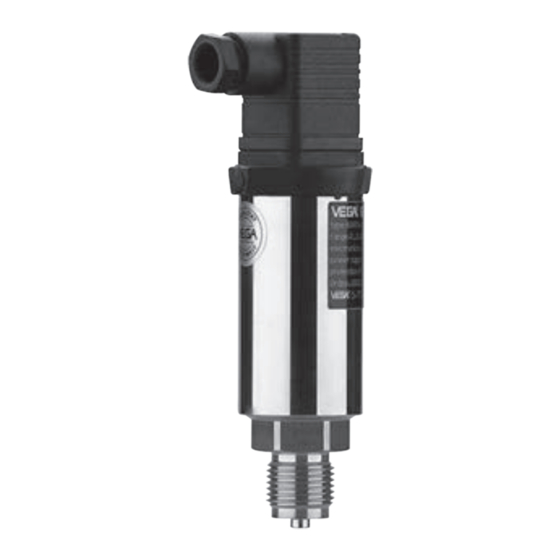
Pressure transmitter
Hide thumbs
Also See for VEGABAR 14:
- Operating instructions manual (32 pages) ,
- Operating instructions manual (28 pages)
Table of Contents
Advertisement
Quick Links
Advertisement
Table of Contents

Related Manuals for Vega VEGABAR 14


Summary of Contents for Vega VEGABAR 14
-
Page 1: Operating Instructions
Operating Instructions VEGABAR 14... -
Page 2: Table Of Contents
CE conformity ..........7 Environmentally responsible behaviour ..7 3 Product description Configuration ..........8 Principle of operation ......... 8 Adjustment ..........9 Storage and transport ........ 9 4 Mounting Mounting procedure ........ 10 Mounting examples ......... 12 VEGABAR 14... - Page 3 Connection procedure ......16 Wiring plans ..........17 6 Set-up .............. 18 7 Maintenance and fault rectification Maintenance ..........19 Fault rectification ........19 8 Dismounting Dismounting procedure ......20 Disposal ..........20 Supplement Technical data ..........21 Dimensions ............25 VEGABAR 14...
-
Page 4: About This Document
This symbol indicates helpful additional information. Caution This symbol informs you of a possible and danger- ous situation. Ignoring this cautionary note can impair the person and/or the instrument. Ex applications This symbol indicates special instructions for Ex ap- plications. VEGABAR 14... - Page 5 About this document • List The dot put in front indicates a list with no implied sequence. Action –> This arrow indicates a single action. Sequence Numbers set in front indicate successive steps in a procedure. VEGABAR 14...
-
Page 6: For Your Safety
VEGA personnel. 2.2 Appropriate use VEGABAR 14 is a process pressure transmitter for gauge or absolute pressure measurement. 2.3 Warning about misuse Inappropriate or incorrect use of the instrument can give rise to application-specific hazards, e.g. -
Page 7: Ce Conformity
For your safety 2.5 CE conformity The VEGABAR 14 process pressure transmitter is in CE conformity with EMC (89/336/EWG) and NSR (73/23/EWG) and fulfils the Namur recommendations NE 21. The conformity has been evaluated acc. to the follow- ing standards:... -
Page 8: Product Description
(via the ceramic diaphragm) which is converted into a 4... 20 mA signal. Power supply VEGABAR 14 has a two-wire, 4 ... 20 mA electronics module for power supply with 12 ... 30 V DC. VEGABAR 14... -
Page 9: Adjustment
Product description 3.3 Adjustment VEGABAR 14 with plug connection is provided with a potentiometer for zero point correction. VEGABAR 14 with direct cable outlet has no adjustment functions. 3.4 Storage and transport Your instrument was protected by packaging during Packing transport. -
Page 10: Mounting
Mounting 4 Mounting 4.1 Mounting procedure Select installation position VEGABAR 14 functions in any installation position. It is mounted acc. to the same guidelines as a manom- eter (DIN EN 839-2) According to the application, we recommend block- ing valve or siphons from VEGA’s line of mounting accessories. - Page 11 Mounting –> Screw VEGABAR into the welded socket. –> Tighten the hexagon screw on the process fitting. • jaw span 27 mm. max. 50 Nm Fig. 1: Mounting VEGABAR VEGABAR 14...
-
Page 12: Mounting Examples
The function of the accessory can in some cases also be achieved by other means (e.g. condensate receptacle instead of siphon). Measurement in gases Fig. 2: Mounting on blocking valve for measurement in gases. Mount- ing position above tapping point enables condensation to flow back. VEGABAR 14... - Page 13 Mounting Measurement in vapours Fig. 3: Mounting with blocking valve and siphon in U-form for meas- urement in vapours Fig. 4: Mounting with blocking valve and siphon in circular form for measurement in vapours VEGABAR 14...
-
Page 14: Vegabar
Mounting Measurement in hot gases Fig. 5: Mounting on blocking valve with extended effective pressure line for measurement in hot gases. Mounting position above tapping point enables condensation to flow back. VEGABAR 14... -
Page 15: Connect Power Supply
Provide a reliable separation between the supply circuit and the mains circuits acc. to DIN VDE 0106 part 101. The VEGA power supply units VEGATRENN 149AEx, VEGASTAB 690, VEGADIS 371 as well as all VEGAMETs meet this requirement. When using one of these instruments, protection class III is ensured for VEGABAR 14. -
Page 16: Connection Procedure
5 Lead the cable through the cable entry and into the plug housing 6 Connect the wire ends to the screw terminals acc. to the wiring plan Plug housing Cable entry Plug insert Fig. 7: Connection to the screw terminals VEGABAR 14... -
Page 17: Wiring Plans
12 … 30 V DC Fig. 8: Wiring plan for angle plug connector acc. to DIN 43560 Cable outlet – Power supply 12 … 30 V DC – Cable screen – Fig. 9: Wiring plan for direct cable outlet VEGABAR 14... -
Page 18: Set-Up
After mounting and electrical connection, VEGABAR 14 is ready for operation. –> Switch on power supply VEGABAR 14 delivers a current of 4 ... 20 mA ac- cording to the actual process pressure. Further settings are not necessary. Correct zero point... -
Page 19: Maintenance And Fault Rectification
Maintenance and fault rectification 7 Maintenance and fault rectification 7.1 Maintenance VEGABAR 14 process pressure transmitters are maintenance-free 7.2 Fault rectification Fault Possible reason Rectifying measure 4 … 20 mA no atmospheric Check pressure signal pressure compensation compensation with- transient... -
Page 20: Dismounting
8.2 Disposal VEGABAR 14 consists of materials which can be recycled by specialised recycling companies. We have purposely designed the electronic modules to be easily separable. Mark the instrument as scrap and dispose of it according to government regula- tions. -
Page 21: Supplement Technical Data
Supplement Supplement Technical data General data Instrument name Process pressure transmitter VEGABAR 14 Materials, wetted parts – process fitting stainless steel 1.4571 ® – diaphragm sapphire ceramics (99.9 % oxide ceramics) – seal Viton, EPDM Materials, non-wetted parts – housing brass nickel-plated –... - Page 22 65 bar/6500 kPa 0…6.0 bar/0…600 kPa 90 bar/9000 kPa 0…10.0 bar/0…1000 kPa 90 bar/9000 kPa 0…16.0 bar/0…1600 kPa 130 bar/13000 kPa 0…25.0 bar/0…2500 kPa 200 bar/20000 kPa 0…40.0 bar/0…4000 kPa 200 bar/20000 kPa 0…60.0 bar/0…6000 kPa 200 bar/20000 kPa VEGABAR 14...
- Page 23 PG 9 (for cables-ø 4.5 … 7 mm) Adjustment element Trimmer potentiometer for zero point adjustment Tested according to the guidelines of the German Lloyd, characteristics 2. Only for the version with connecting plug The maintenance of the housing protection class VEGABAR 14...
- Page 24 (see load diagram) voltage of the external energy U in Volt Electrical protective measures Protection class – with plug connection DIN 43 560 A IP 65 – with direct cable outlet IP 67 Protection class Overvoltage category VEGABAR 14...
-
Page 25: Dimensions
Notes Dimensions ø38 SW 27 ø3 G ¼ ¼" NPT ø3 ø6 ø17,5 ½" NPT ø6 G ½ A G ½ A M20x1,5 VEGABAR 14... - Page 26 Notes VEGABAR 14...
- Page 27 Notes VEGABAR 14...
- Page 28 VEGA Grieshaber KG Am Hohenstein 113 77761 Schiltach Germany Phone 07836 50-0 07836 50-201 E-Mail info@de.vega.com www.vega.com ISO 9001 All statements concerning scope of delivery, application, practical use and operating conditions of the sensors and processing systems correspond to the latest information at...
Need help?
Do you have a question about the VEGABAR 14 and is the answer not in the manual?
Questions and answers