Table of Contents
Advertisement
Quick Links
Advertisement
Table of Contents

Subscribe to Our Youtube Channel
Related Manuals for Veripos LD5


Summary of Contents for Veripos LD5
- Page 1 Operation Manual (A & B Variants) VERIPOS...
- Page 2 Updated for Phase 5 Software 28.01.2014 Amended Serial Pin-outs REVISION DATE DESCRIPTION ORIGINATOR CHECKED APPROVED CLIENT APPR Document Title: LD5 Operations Manual (A & B Variants) File Ref: AB-V-MA-00539 Rev No: Page 2 Date: 12.01.2017 LD5 Operation Manual (A & B Variants)
-
Page 3: Table Of Contents
ONFIG 2.9.1 Config / I/O ..................35 2.9.2 Config / I/O / COM1 COM2 or COM3 ..........35 2.9.3 Config / I/O / EXT RTCM ..............37 Rev No: Page 3 Date: 12.01.2017 LD5 Operation Manual (A & B Variants) - Page 4 Service access license ..............49 5.1.2 Service notification form ..............49 ................. 50 LOBAL COVERAGE CHART ....................51 PORTS 5.3.1 LD5 COM and IP sockets ..............51 LD5 COM ports .................... 53 LD5 M ................54 ENU STRUCTURE NMEA S ..................58 ENTENCES CONTACT INFORMATION ................
-
Page 5: Introduction
1 Introduction General This manual is applicable to LD5’s which are A or B variants. For LD5 C variants, please refer to the LD5 (C Variant) Operations manual. For installation guidance please see the LD5 Installation manual, which applies to all LD5 variants . -
Page 6: Terms And Abbreviations
Terms and abbreviations VERIPOS proprietary logging format APEX A Veripos PPP DGNSS service using GPS APEX² A Veripos PPP DGNSS service using GPS and GLONASS DGPS Differential GPS DGNSS Differential GNSS Dilution of Precision Electronics Industry Association (this document uses the previous terminology “RS”... - Page 7 Global DGPS service provider VOSS VERIPOS Online Support System WAAS Wide Area Augmentation System (SBAS implementation in USA) WEEE Waste Electrical and Electronic Equipment Word Error Rate Rev No: Page 5 Date: 12.01.2017 LD5 Operation Manual (A & B Variants)
-
Page 8: Document Conventions
If the troubleshooting section does not resolve the issue contact the VERIPOS helpdesk for further assistance. Users can also create a fault ticket on the help.veripos.com web site. This will ensure contact details and the description of the fault are correctly recorded. -
Page 9: Veripos Online Support System (Voss)
In order for the equipment to decode corrections and output positions it must be enabled. The enable/disable procedure is detailed in section 2.6.2 onwards. When the Veripos services are not required some contracts may allow for disabling the service to avoid charges. NOTE To use VERIPOS correction signals a contract between the user’s company... -
Page 10: Waste Electrical And Electronic Equipment
Hazardous Substances) complements the WEEE directive by banning the presence of specific hazardous substances in the products at the design phase. The WEEE directive covers all VERIPOS products imported into the EU as of August 13 2005. EU-based manufacturers, distributors, retailers... -
Page 11: Disclaimer
(including legal costs), expenses and liabilities of any kind and nature, invoked against Veripos by any third party, for or arising out of, any alleged infringement of any patent or proprietary or protected right arising out of or in connection... - Page 12 Rev No: Page 10 Date: 12.01.2017 LD5 Operation Manual (A & B Variants)
-
Page 13: Ld5 Operation
2 LD5 Operation The controls for working with the LD5 are all available on the front panel. The LD5 control panel is used to configure the unit using the main screen display. LD5 Variants 2.1.1 Available LD5 Variants There are various LD5 IMU variants available. The variants depict the hardware installed in the unit. - Page 14 The table below shows the LD5 A and B variants which are available, depending on the user’s requirements; Hardware Installed Antenna Connection Variants Modules L-Band L-Band Only (N-Type Connector) Combined L-Band and GNSS (N-Type L-Band, GNSS Connector) Combined L-Band, GNSS (N-Type...
-
Page 15: Identifying Ld5 Variant
2.1.2 Identifying LD5 Variant There are two methods generally used to identify which LD5 variant you have: There should be a sticker located on top of the LD5 chassis. Part of the information is the model or variant version: A2 Variant... -
Page 16: Modes
Maint mode should only be used under instruction from VERIPOS. The LD5 B Variant has only two operating modes: LD5 and QC (No Maint mode) The LD5 will log data internally which can be used by VERIPOS during support cases. -
Page 17: Satellite Constellations
GPS or GPS+GLONASS satellite constellations. Variants B2 and B3 are all preconfigured to use GPS+GLONASS satellite constellations. GLONASS satellites will only be used in the solution if the LD5 is enabled to receive and use VERIPOS GLONASS corrections. Rev No:... -
Page 18: Views And Controls
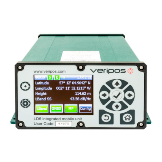
Navigation panel. Arrow keys are used to move through menu items and tick key () is used to accept an item. Home Return User code (5 digits) Receiver card icons (3 max.) Rev No: Page 16 Date: 12.01.2017 LD5 Operation Manual (A & B Variants) - Page 19 Ethernet RJ45 connector * TNC antenna connector (use depends on variant/mod) USB type B connector * Grounding point DC power connector (12–24 VDC) * Do not connect devices to LD5 without first performing a virus scan! Rev No: Page 17 Date: 12.01.2017...
-
Page 20: Ld5 Start Up
Wait a few minutes while a self-test is performed. Following successful test you will see the main or home screen. The LD5 may be disabled when first powered up. If the unit is disabled the L- band, GNSS, and Enabled indicator icons will be red. -
Page 21: Ld5 Mode Selection
Configuration of each installed receiver card is achieved using the arrows, return, home and accept (tick) control pad on the right hand side of the LD5 front panel to navigate to and select the corresponding on screen button. -
Page 22: L-Band Receiver
Decoder version Bootloader version VERIPOS may request these details during support queries. 2.6.2 L-Band / Status / Device Status This view allows the user to review the Signal Strength, selected Beam, whether or not the unit has Frame Sync or Signal Lock, and whether or not the LD5 is enabled. -
Page 23: L-Band / Config / Beam Selection
Reference stations on RTCMa are used internally and are also available for output to other devices. Veripos recommend in most cases that all stations are enabled. The LD5 will automatically use the closest six stations in internal position computations. 2.6.4 L-Band / Config / Beam selection This step describes how to select a satellite beam to receive VERIPOS correction data. -
Page 24: L-Band / Config / Antenna Bias
The antenna bias menu allows the antenna voltage to be turned On or Off out from the ANT connection at the rear of the LD5. When using a VERIPOS supplied antenna, the antenna voltage should normally be on as the antenna requires power to operate. -
Page 25: Gnss Receiver
This screen shows the firmware installed on the GNSS receiver. From the Home screen select GNSS/ Status/ Module Info. The information displayed on this menu will differ between ‘A’ and ‘B’ LD5 variants. The information displayed in each variant is detailed below. -
Page 26: Gnss / Status / Sv Info
‘B’ variant LD5 GNSS cards have the below standard default permissions: 2.7.2 GNSS / Status / SV Info This screen shows the number of satellites tracked by the LD5. It can also show if the GNSS receiver has GLONASS capability. From the Home screen select GNSS/ Status/ SV Info If the GLONASS constellation is not activated on the GNSS receiver card, this screen will show against GLO as “Not Available”. -
Page 27: Gnss / Status / Position Info
Ultra or Standard and number of SVs used. From the Home screen select GNSS/ Status/ Position Info NOTE The Height displayed is WGS84 ellipsoidal height, not the antenna height above MSL. Rev No: Page 25 Date: 12.01.2017 LD5 Operation Manual (A & B Variants) -
Page 28: Gnss / Status / Dop Values
2.7.5 GNSS / Status / Masks This screen shows the Mask values set on the GNSS receiver. The Mask Values are setup automatically by the LD5 unit and cannot be set by the user. From the Home screen select GNSS/ Status/ Masks The information displayed on this menu will differ between ‘A’... -
Page 29: Gnss / Config
From the Home screen select GNSS/ Config/ PPS. Move the cursor to the appropriate box using the arrow keys. Select () to amend then navigate to Apply to select the different options. Rev No: Page 27 Date: 12.01.2017 LD5 Operation Manual (A & B Variants) -
Page 30: Gnss / Config / Ppp Config
2.7.8 GNSS / Config / PPP Config If the LD5 is enabled for only one PPP service, the PPP Config setting must be set to the same service otherwise no PPP solution will be computed. Changing the PPP Config settings will re-initialise a new PPP calculation, which will take time to settle and a PPP position output to be available. -
Page 31: Gnss / Config / Sbas/Rtk
PPP service. 2.7.9 GNSS / Config / SBAS/RTK This menu allows the user to configure the SBAS and RTK options. The SBAS and RTK can be turned on or off as an alternative solution to Veripos calculations. NOTE RTK options will only be displayed if RTK permissions have been enabled on the GNSS card. -
Page 32: Gnss / Config / Nmea Config
To enable or disable NMEA messages, move the cursor to the appropriate box using the arrow keys. Then use the tick () key to toggle stations between On and Off. Available NMEA message types: Rev No: Page 30 Date: 12.01.2017 LD5 Operation Manual (A & B Variants) -
Page 33: Gnss / Help
This is to prompt the user to ensure that a suitable baud rate is selected if outputting an excessive number of messages via COM ports: 2.7.12 GNSS / Help This screen shows VERIPOS Helpdesk contact details. Rev No: Page 31 Date: 12.01.2017 LD5 Operation Manual (A & B Variants) -
Page 34: Mf Beacon (Iala) Receiver Config And Status
MF Beacon (IALA) Receiver Config and Status The LD5 MF card, status information and configuration settings are accessed from the ‘Home’ page. 2.8.1 MF / Status / Module Info This menu displays details of the MF receiver card fitted such as model and firmware version. -
Page 35: Mf / Config / Mode
This setting uses the station with the strongest signal received This setting uses the closest MF beacon station to the receiver’s Autodist location. This function uses a station database stored in the LD5 unit. Manual This setting requires the user to enter a frequency and data rate from Manual Tune Menu or select a station from the Station Tune Menu. -
Page 36: Mf / Config / Manual Tune
This menu allows the user to turn on or turn off the Antenna Voltage on the MF antenna connector on the rear of the LD5 unit. For LD5 A3 (Mod1) this is controlled by the L-Band config settings. For LD5 A3 (Mod2) the MF / GNSS voltage is ALWAYS ON. -
Page 37: Ld5 Config
LD5 Config This menu allows access to the configuration of the LD5 unit. Configuration of serial ports, network settings and operating modes are available in this menu. Access from Home/ Config. 2.9.1 Config / I/O This page allows the user to select the pages required to configure the data outputs and inputs. - Page 38 Select () to amend then navigate to Next and select () to move onto the next config page. Configure the Protocol, Baud Rate, Data Bits, Parity and Stop Bits Use Left/ Right arrow buttons to move between the 2 pages Rev No: Page 36 Date: 12.01.2017 LD5 Operation Manual (A & B Variants)
-
Page 39: Config / I/O / Ext Rtcm
Then navigate to Apply and select () to finish the configuration. 2.9.3 Config / I/O / EXT RTCM This menu is not present on B variant LD5’s. B variants only accept VERIPOS RTCM correction data therefore no additional configuration is required. -
Page 40: Config / Network
The LD5 continuously logs raw data internally. The format in which this raw data is logged depends on the LD5 variant in use. Data logging is only enabled when the LD5 is in ‘LD5’ Operating Mode. Data logging is disabled when in ‘QC’ or ‘Maint’ Modes. - Page 41 ‘A’ Variant LD5’s log data in a VERIPOS proprietary (ALF) format. ‘B’ Variant LD5’s log data in Novatel Binary (NBF) format. In both cases, the LD5 keeps a rolling log, which means disk space will never run out as once the set duration has been reached, the oldest logged data will start to be overwritten.
- Page 42 Press () to open the list of available logging periods: Select the desired logging duration from the list then navigate to the Apply icon and press (). Rev No: Page 40 Date: 12.01.2017 LD5 Operation Manual (A & B Variants)
-
Page 43: Config / Config
2.9.8 Config / Config This menu allows the user to configure the mode of use for the LD5 (LD5 or QC), change day/night screen settings and view the LD5 software version number and LD5 unit variant. The second page allows for adjusting the screen dimmer delay period (mins). -
Page 44: Ld5 Use With Rtk Corrections
The RTK message format needs to be in RTCMv2 format. To input RTK corrections: Ensure that the LD5 is in LD5 Mode (Config/ Config and Operating Mode is “LD5” - see Section 2.9.8). Configure the LD5 COM port to receive 3rd party RTCM corrections. Go to Config/ I/O / (COM port used) and set to “Ext RTCM”... - Page 45 Connect the Serial connection from the RTK source to the LD5 COM port. From the Home page go to GNSS/ Config/ SBAS/ RTK, highlight it, select to on and Apply. The LD5 will now be capable of using third party RTK corrections.
-
Page 46: Veripos Software Compatibility
3 VERIPOS Software Compatibility The LD5 (A & B variants) can be used with the VERIPOS DP Orion visualisation software. They are also compatible with the VERIPOS Verify QC software. The table below details the compatible Verify QC software version(s) for... -
Page 47: Troubleshooting
4 Troubleshooting Overview of troubleshooting The LD5 uses a colour screen and navigation panel to access an embedded Windows CE The system contains no user-serviceable parts. The cover should not be removed except under the guidance of a VERIPOS engineer, first ensuring that the unit is isolated from all AC and DC power supplies. -
Page 48: Enable/Disable Faults
- beam L-Band/ Status/Device Status. used has not been changed. If necessary consult the Chart in the Reference information chapter and if required select the regional beam. Rev No: Page 46 Date: 12.01.2017 LD5 Operation Manual (A & B Variants) - Page 49 For Verify QC, consult the Verify QC Operations Manual for guidance on its’ use where provided in conjunction with the LD5. For problems relating to antennas or cables, see the LD5 Installation manual and the Antennas and Coaxial guide before installing replacement equipment and for a general guide to equipment installation.
-
Page 50: Veripos Helpdesk
Full vessel name correct identification is important; VERIPOS may have installation drawings. Name of parent company User Code (on front panel) and current ‘Access code’ of LD5, see the operation chapter for details. Current status of the LD5 ... -
Page 51: Reference Information
The equipment cannot be used until an enable code is obtained from the VERIPOS Helpdesk. The Helpdesk is not authorised to issue a code unless an active SAL exists and its number can be determined. To avoid delays the user should keep a record of the SAL number associated with his unit. -
Page 52: Global Coverage Chart
Global coverage chart Global Coverage Chart updated VERIPOS Global coverage chart can be found on the VERIPOS Online support system http://help.veripos.com Rev No: Page 50 Date: 12.01.2017 LD5 Operation Manual (A & B Variants) -
Page 53: Com Ports
COM ports 5.3.1 LD5 COM and IP sockets A Variant LD5 Mode – Default Data Stream Settings Mode Data stream Default COM port Baud rate Socket / Assignment L-Band RTCMa COM 1 9600 9001 L-Band RTCMb Unassigned 9600 9002 L-Band Config... - Page 54 Maint Mode - Default Data Stream Settings Use only under direction of a qualified Veripos technician! Maint Mode Stream Default COM port Baud rate Socket / Assignment L-Band RTCMa COM 1 9600 9001 L-Band RTCMb Unassigned 9600 9002 L-Band Config...
-
Page 55: Ld5 Com Ports
Default configuration for each COM port is: • 8 data bits • No parity • 1 stop bit This information may be required when interfacing to ships systems using RS-232/422 standards. The LD5 is the transmitting device. Function RS-232 RS-422 Not connected Not connected Tx(-) Rx(-) -
Page 56: Ld5 Menu Structure
LD5 Menu structure Overall Menu Structure of the LD5 Rev No: Page 54 Date: 12.01.2017 LD5 Operation Manual (A & B Variants) - Page 57 L-Band Menu Structure of the LD5 GNSS Menu Structure of the LD5 Rev No: Page 55 Date: 12.01.2017 LD5 Operation Manual (A & B Variants)
- Page 58 MF Menu Structure of the LD5 Rev No: Page 56 Date: 12.01.2017 LD5 Operation Manual (A & B Variants)
- Page 59 Config Menu Structure of the LD5 Rev No: Page 57 Date: 12.01.2017 LD5 Operation Manual (A & B Variants)
-
Page 60: Nmea Sentences
NOTE: The number of decimal places in the Latitude and Longitude values is configurable via the LD5 in the GNSS/ Config/ NMEA Config under NMEA Precision. Between 5 and 8 decimal places are selectable. - Page 61 UTC time in hours, minutes, seconds of the GPS position dd,mm,yyy Day,Month,Year (UTC) local zone hours (00 to +/-13 hrs) local zone minutes (00 to 59) *hh<CR><LF> checksum, carriage return and line feed Rev No: Page 59 Date: 12.01.2017 LD5 Operation Manual (A & B Variants)
- Page 62 24 satellites, this gives a range of 65 through 88. The numbers 89 through 96 are available if slot numbers above 24 are allocated to on-orbit spares. Rev No: Page 60 Date: 12.01.2017 LD5 Operation Manual (A & B Variants)
- Page 63 24 satellites, this gives a range of 65 through 88. The numbers 89 through 96 are available if slot numbers above 24 are allocated to on-orbit spares. Rev No: Page 61 Date: 12.01.2017 LD5 Operation Manual (A & B Variants)
- Page 64 Receivers that don't have a magnetic deviation (variation) table built in will null out the Magnetic track made good. Rev No: Page 62 Date: 12.01.2017 LD5 Operation Manual (A & B Variants)
- Page 65 Geoidal height age of differential GPS data nnnn Differential reference station ID, 0000 to 1023 *cc<CR><LF> checksum, carriage return and line feed Rev No: Page 63 Date: 12.01.2017 LD5 Operation Manual (A & B Variants)
- Page 66 3) When multiple GRS sentences are being sent then their order of transmission must match the order of corresponding GSA sentences. Listeners shall keep track of pairs of GSA and GRS sentences and discard data if pairs are incomplete. Rev No: Page 64 Date: 12.01.2017 LD5 Operation Manual (A & B Variants)
- Page 67 Note that, as of the 2.3 release of NMEA, there is a new field in the RMC sentence at the end just prior to the checksum. For more information on this field. Rev No: Page 65 Date: 12.01.2017 LD5 Operation Manual (A & B Variants)
-
Page 68: Contact Information
6 Contact information All initial contacts regarding technical or support issues should be initially addressed to the VERIPOS Helpdesk. Where appropriate, the Helpdesk will refer issues to the regional operations and engineering teams. VERIPOS Helpdesk Helpdesk telephone +44 (0)1224 965900 Helpdesk e-mail helpdesk@veripos.com...
Need help?
Do you have a question about the LD5 and is the answer not in the manual?
Questions and answers