Table of Contents
Advertisement
Advertisement
Table of Contents

Related Manuals for Fisher Scientific AccuSpin Micro 17


Summary of Contents for Fisher Scientific AccuSpin Micro 17
- Page 1 AccuSpin Micro 17 / 17R Instructions for use...
- Page 2 How to use this manual Use this manual to get acquainted with your centrifuge and its accessories. Overleaf you will find a graphic illustra- tion of the control panel with a survey of The manual helps you to avoid inappropriate handling. the most important functions Make sure to keep it always close to the centrifuge.
- Page 3 (only for instruments with refrigeration unit) temperature speed/RCF run time quick run rotor turns open lid stop start rpm/RCF “set“ keys “set“ keys pre-temperature-regulation switch key (only for instruments with refrigeration unit) display Before switching on the centrifuge Note that “min ”...
- Page 4 Control panel Keys Display panels start: start of the centrifuge Speed / RCF stop: manually stop of a run Resting state: current value (0) or pre-selected set-point value open lid: open lid During run: present current value of speed or RCF (possible only with the instrument switched on and (after activation of switch key) standstill of the rotor)
-
Page 5: Table Of Contents
Concerning the RCF value ......... 29 Selecting the run time ..........30 Accessories ..........11 Run time selection ..........30 Rotors for the accuSpin Micro 17......12 Continuous operation ......... 30 Rotors for the accuSpin Micro 17R ......14 Setting the temperature.......... 31 Adapter.............. - Page 6 Inhalt Stopping the centrifuge .......... 34 Speed/RCF diagram..........60 Preset run time ........... 34 Autoclaving protocol ..........66 Continuous operation ......... 34 Index ............69 Short-time centrifugation ........34 Removing the rotor..........35 Audible alarm ............35 Turning off the centrifuge ........36 WEEE Compliance:..........
-
Page 7: For Your Safety
For your safety ® Fisher Scientific centrifuges are manufactured accord- For your safety ing to current technical standards and regulations. Nonetheless, centrifuges may pose danger to indi- Safety instructions in this manual viduals and surrounding if • they are not used as designed This symbol denotes potential hazards •... -
Page 8: Proper Use
For your safety being centrifuged, aerosol-tight bio-seals have to be Proper use used. The centrifuge is designed to separate liquid- For materials in a higher risk group, more than one suspended materials having different densities and precaution is required. particle size (maximum sample density is 1.2 g/cm³ at •... -
Page 9: Conformity To Current Standards
- for 120 V only • the centrifuge may only be carried out by individu- ® als authorized by Fisher Scientific - for 230 V only • Please get acquainted with the details of the test stan- dards from the technical data... - Page 10 For your safety for your notes...
-
Page 11: Description Of The Instrument
• cable for mains connection • this Manual Safety systems The accuSpin Micro 17 and the accuSpin Micro 17R are equipped with several safety measures: • Housing made of highly impact-resistant plastic; Extra steel armor. • Lid with window and lid latch with locking mecha-... -
Page 12: Properties
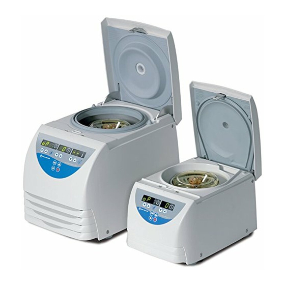
If you press the chosen key The accuSpin Micro 17 and the accuSpin Micro 17R and hold it pressed, the respective chosen measure- are tabletop centrifuges designed for the use in bio- ment value increases or decreases continuously, at chemical and medical laboratories. -
Page 13: Before Use
Before use Before use Transport and installation the centrifuge Where to install the centrifuge The centrifuge may only be used indoors. Its location Transport the centrifuge only in must meet the following criteria: the upright position, using the • A safety zone of 30 cm around the centrifuge must special box provided with the in- be maintained. -
Page 14: Mains Connection
Before use Mains connection Removing the transport protection Make sure that the mains supply and the frequency Before using the centrifuge, make sure meet the specifications printed on the centrifuge type that the rotor transport protection has plate. been removed! First turn the mains switch of the centrifuge off (press Turn the instrument on at the power switch. -
Page 15: Accessories
Accessories Accessories The centrifuge is delivered complete with a fixed-angle rotor with 24 holes for placing Micro liter tubes with a volume of 1.5 or 2.0 ml. In addition you may order three sets of adapters con- taining 24 reduction sleeves each. With these adapters you can centrifuge all commercially available Micro liter tubes with a volume between 0.2 and 0.6 ml as well as 0.2-ml PCR reaction vessels. -
Page 16: Rotors For The Accuspin Micro 17
Accessories Rotors for the accuSpin Micro 17 Table 1: Performance characteristics for accuspin Micro 17 rotor designation Micro liter-rotor Micro liter-rotor Dual-rotor 24 x 2 ml 36 x 0,5 ml 18 x 2 ml / 0,5 ml order no. 75003524... - Page 17 Accessories Table 1: Performance characteristics for accuSpin Micro 17 rotor designation PCR-rotor PCR-rotor Haematocrit-rotor 4 x 8 8 x 8 order no. 75003434 75003489 75003473 places / volume 4 x PCR-Strip 8 x PCR-Strip 24 x Blood capillary tubes 75 mm...
-
Page 18: Rotors For The Accuspin Micro 17R
Accessories Rotors for the accuSpin Micro 17R Table 3: Performance characteristics for accuSpin Micro17R differences of 120V instruments are shown in parentheses rotor designation Microliter-rotor Microliter-rotor Dual-rotor 24 x 2 ml 36 x 0,5 ml 18 x 2 ml / 0,5 ml order no. - Page 19 Accessories Table 3: Performance characteristics for accuSpin Micro 17R rotor designation PCR-rotor 4 x 8 PCR-rotor 8 x 8 Haematocrit-rotor order no. 75003473 75003440 75003489 places / volume 4 x PCR-Strip 8 x PCR-Strip 24 x Blood capillary tubes 75 mm maximum permissible load [ g ] 4 x 4 8 x 4...
-
Page 20: Adapter
Accessories Adapter Table 3: Adapter max. tube tube capacity number color no. of adapter for dimensions [ ml ] per set order Micro liter rotor 7500 3424 x length [ mm ] reduction sleeve PCR grey 7600 3750 reduction sleeve 0,5 / 0,6 turquoise 7600 3758... -
Page 21: Handling The Rotor
Handling the rotor Rotor lid with a spring lock Handling the rotor Opening Rotor temperature The rotor lid is held on the central rotor nut integrated The rotors are only to be used within into the rotor the temperature range from - 9°C to +40°C. -
Page 22: Operation Without Rotor Lid
Handling the rotor - Closing Operation without rotor lid For closing the rotor place the rotor lid centrically on If you are going to operate the rotor without the rotor lid the rotor nut. the aerosol-seals must be removed prior to use. Press the rotor lid down now until the lock is audio- Aerosol-seals visually locked... -
Page 23: Rotor Lid With Screw Plug
Handling the rotor Rotor lid with screw plug For this kind of rotor the rotor lid will be held centrically These rotors are not designed for on the rotor collar. aerosoltight applications! The O-Ring in the rotor collar pro- vides only for tight fit of screw plug. The external lid lip can not be sealed for these rotors. -
Page 24: Aerosol-Tight Application
Handling the rotor Tubes are only to be filled to a level where the sample Aerosol-tight application does not reach the brim of the tubes during centrifuga- Only with the designated rotors! tion. See the rotor tables from page 12 Please observe the permissible filling volumes! Nominal volume: Permissible volume:... - Page 25 Handling the rotor The following steps have to be carried out: Correct operation when filling the sample tubes and • closing the rotor lid are prerequisites for aerosol bio- Lubricate the seals before inserting them containment. (lubricant order no. 76003500) Prior to each application, the seals in the rotors have to be checked for correct fit, abrasion or damage and...
-
Page 26: Checking For Aerosol-Tightness
Handling the rotor Checking for aerosol-tightness For a quick test one can check the fixed angle rotors The checking of the rotor type and bucket was done according to the following procedure: according to the dynamic microbiological test proce- • Slightly grease all seals. -
Page 27: Operation
Operation Operation Opening the lid Switching on the centrifuge For activating the lid release the centrifuge Set the main power switch of the instrument. must be connected to mains and switched For a couple of seconds the following reading appears in the control panel (the temperature display field only) To open the lid press the „open-lid“-button The display reads:... -
Page 28: Installing The Rotor
Operation Installing the rotor Proceed as follows: 1. Open the centrifuge lid and make sure that the Improper or improperly combined rotor chamber and the rotor are clean. Remove accessories may cause severe dam- eventual dust, foreign material or sample residues. age to the centrifuge! The thread and the O-Ring on the motor shaft must be in perfect condition. - Page 29 Operation 4. Press the rotor gently down until it stops. 5. Grip the rotor tightly and use the provided rotor wrench to tighten up the rotor. Do not push the rotor down using force. If the rotor can not be tightened, you have to remove it carefully, align the notch and the retaining pin again and re-install it.
-
Page 30: Loading The Rotor
Operation Filling the centrifuge tubes Loading the rotor Maximum load Please note that plastic sample vessels only have a limited service life - particularly when Overloading may cause the rotor used at maximum performance (rpm or tem- to explode! perature) - and must be replaced as neces- sary! Exploding parts may severely damage the centrifuge! -
Page 31: Placing The Tubes In The Rotor
Operation Placing the tubes in the rotor Uneven loading may lead to damage of The rotor must be loaded symmetrically. When loading the rotor and centrifuge in extreme the rotor only partially, you must ensure that opposite cases. Imbalance not only causes a bores always receive tubes of equal weight (when cen- noisy run, but also causes premature trifuging a single sample, place a centrifuge tube e.g. -
Page 32: Entering Parameters
Operation Entering parameters Switching from speed to RCF display By pressing the key briefly, you increase or decrease the Upon turning on the centrifuge, the speed display is speed in one step (of 100 rpm). set. This option is supposed to be By activating the selection key you can switch to the used for small changes... -
Page 33: Entering The Rcf Value
Operation Concerning the RCF value Entering the RCF value The relative centrifugal force (RCF) is given in multi- You can adjust the RCF pre-selected value in steps of ples of the earth gravity g. It is a dimensionless number 100 xg. The setting of pre-selected value is entered value that allows one to compare the efficiency of analogously to the speed. -
Page 34: Selecting The Run Time
Operation Selecting the run time 3. Release the key as soon as you have reached the You can select a run time between 1 and 99 min or desired value and fine tune if necessary by repeat- continuous operation [hd]. edly briefly pressing one of the keys. -
Page 35: Setting The Temperature
Operation 3. Release the key as soon as you are close to the Setting the temperature desired value and fine tune if necessary by repeat- To determine the sample temperature for instruments edly briefly pressing the key. The display flashes with refrigeration unit, operate as adviced: for a few seconds and then turns to permanent 1. -
Page 36: Pretemp
Operation Pretemp If you wish to change the temperature of your samples, The pretemp-function allows quick and easy tempering please consider that the time required for temperature of the unloaded rotor. adjustment is prolonged. The farther apart initial and After calling the function by pressing the key only final temperature, the longer it takes for the tempera- the desired temperature still must be chosed. -
Page 37: Starting The Centrifuge
Operation Changing the settings during the run Starting the centrifuge You can change the settings while the rotor is spinning. Once the rotor is properly installed, the main switch Trough a one-time pressing of any key of the control turned on and the lid closed, you can start the centri- panel, the current value will switch into the pre- fuge. -
Page 38: Stopping The Centrifuge
Operation Stopping the centrifuge Short-time centrifugation Preset run time For short-term operation, the centrifuge is equipped with the "quick run" function. Normally the run time has been pre-selected, and all you have to do, is to wait until the centrifuge terminates Short-term centrifugation is started by pressing the the run automatically. -
Page 39: Removing The Rotor
Operation Removing the rotor Audible alarm To remove the rotor you have to proceed in the reserve Accompanying all error messages, a warning signal is order as at the installation of the rotor. given out which can be silenced upon pressing any key. -
Page 40: Turning Off The Centrifuge
10 seconds. them. Further information on Fisher Scientific`s compliance The opening of the centrifuge lid is only with these Directives, the recyclers in your country, and ®... -
Page 41: Maintenance And Care
Maintenance and care Cleaning Maintenance and care Maintenance to be performed by the Pull mains plug before cleaning the in- customer strument! For the protection of persons, environment and mate- rial you are obliged to clean the centrifuge regularly Clean the casing, the rotor chamber, the rotor and the and to disinfect it if necessary. -
Page 42: Cleaning The Filter Unit
Maintenance and care Please clean the venting slots regularly! To protect the refrigeration unit, the cooled devices are equipped with an air filter unit. Depending environment situation Sucking grid recommended to clean the filter at least every three months. Disconnect the centrifuge from mains switch before cleaning the venting slots and the filter unit. -
Page 43: Disinfection
Maintenance and care Disinfection If a centrifuge tube containing infectious material Rotor and rotor chamber must be treated with a neu- leaks, during a centrifugation run, you have to disinfect tral, universal desinfectant. Best suited for this purpose immediately the rotor, and/or also the centrifuge. are disinfectant sprays, ensuring that all rotor and ac- cessory surfaces are covered evenly. - Page 44 Maintenance and care Disinfection with bleaching lye 5. Treat the rotor and the rotor lid according to the instructions given for the disinfectant (soaking in These agents contain highly ag- liquid or spraying). You must strictly observe the gressive hypochlorites and must specified action times! not be used with aluminum rotors! 6.
-
Page 45: Decontamination
Maintenance and care The rotor must be cleaned and rinsed with distilled Decontamination water before being autoclaved. Remove the rotor lid, the centrifuge tubes and the adapters. Place plastic For general radioactive decontamination, use a solu- rotors on an even surface to avoid deformation. tion of equal parts of 70% ethanol, 10% SDS and wa- ter. - Page 46 Maintenance and care...
-
Page 47: Troubleshooting
Troubleshooting Troubleshooting Mechanical emergency lid release 1. Make sure the rotor stands still. (control window). In case of a power failure you cannot open the lid nor- mally using the electric emergency release. To permit 2. Unplug the mains cord. unloading even in this case, the centrifuge is equipped 3. - Page 48 Troubleshooting 4. Gently press the centrifuge lid down to disengage the lid-latch. 5. While pressing down the lid push the wire down further until you hear and feel the lid-latch unlock- ing. Remove the auxiliary tool and open the centri- fuge lid.
-
Page 49: Problems You Can Handle Yourself
Troubleshooting Problems you can handle yourself If problems other than those described in the following tables arise, you must consult your nearest au- thorized service. Error Symptom Possible causes and corrective measures Displays remain dark The drive stops. Mains voltage disconnection The rotor stops without 1. - Page 50 Troubleshooting Error Symptom Possible causes and corrective measures – Exceptionally running Imbalance. noise. 1. Stop the centrifuge by pressing the "stop" key, in case of emergency, unplug mains power cord. 2. Wait until the centrifuge comes to a complete stop. 3.
- Page 51 Troubleshooting Error Symptom Possible causes and corrective measures „bAL“ The rotor stops with decel- Imbalance switch releases. eration. 1. Open the instrument by pressing the “lid open” in case. 2. Check whether the rotor is properly loaded. 3. Check whether a broken tube or a damage to the rotor release the imbalance switch.
- Page 52 Troubleshooting Error Symptom Possible causes and corrective measures E-22/E-23 Rotor stops without Error in speed entry deceleration to standstill. Switch the instrument off and on again. Instrument cannot be If the error persists, contact service representative. operated. E-24 Instrument cannot be Wrong status information from the lid-latch.
- Page 53 Troubleshooting Error Symptom Possible causes and corrective measures E-31 Rotor stops without Overtemperature in the motor. deceleration to standstill or 1. Turn instrument off and unplug mains power cord. does not start. 2. Check and clean the venting slots if necessary and re- spectively the filter unit of the cooled centrifuge.
- Page 54 Troubleshooting Error Symptom Possible causes and corrective measures E-41 Rotor stops without Internal program error. deceleration to standstill. Switch the instrument off and on again. Instrument cannot be E-56 If the error persists, contact service representative. operated. E-60 Rotor stops with decelera- Insufficient temperature in the refrigeration unit.
-
Page 55: Contacting Service
Troubleshooting Contacting Service Subsequently, the following readings will be dis- played for 5 seconds each Should you require help from your service represen- SoFt 0 5 8 tative, please indicate the catalog and serial number Software number of your instrument. You will find the pertinent infor- _ 0 1 Software version mation at the specifications, near the socket for the... - Page 56 Troubleshooting for your notes...
-
Page 57: Technical Data
Keys and display panel covered with easy care protective foil Operation "Easycontrol" system Rotor chamber dimensions (D x H) (diameter x height): accuSpin Micro 17 190 mm x 70 mm accuSpin Micro 17R 200 mm x 75 mm Chamber Up to 48 ml of spilled liquids are retained in the chamber and cannot enter the in- strument. -
Page 58: The "Easycontrol" User Interface
Technical data The "Easycontrol" user interface Function Performance Start Start key ( Stop Stop key ( Quick starting and stopping "Quick run" key ( ): short-time run when pressed permanently; stop when re- leased Indication of operating state Spinning rotor indicated by rotating lights (LED) in the speed display panel End of centrifugation Speed display reads "End"... -
Page 59: Performance
Technical data Performance Performance Value/description (accuSpin Micro 17/ 17R in parentheses) environmental conditions indoor use maximum elevation 2000 m above sea level maximum relative humidity 80 % up to 31 °C; linearly decreasing down to 50 % relative humidity at 40 °C. - Page 60 Technical data Performance Value/description dimensions (H x W x D) accuSpin Micro 17 230 mm x 240 mm x 350 mm accuSpin Micro 17R 330 mm x 292 mm x 440 mm weight with rotor accuSpin Micro 17 10,5 kg...
-
Page 61: Electrical Connections
Electrical connections Order no. Voltage Frequency Nominal Power Fuses inside instrument * consumption current accuSpin Micro 17 7500 2460 230 V 50/60 Hz 1,4 A 180 W 2 x 4,0 AT 250V (5 x 20 mm) accuSpin Micro 17 7500 2461... - Page 62 Technical data for your notes...
-
Page 63: Appendix
Appendix Appendix... -
Page 64: Speed/Rcf Diagram
Appendix Speed/RCF diagram Speed/RCF diagram Micro liter rotor 24 x 2 ml 7500 3424 100000 = 14 800 min = 8,6 cm RCF (r ) = 21 058 = 5,1 cm 10000 1000 1000 10000 100000 speed (rpm) - Page 65 Appendix Speed/RCF diagram Micro liter rotor 36 x 0,5 ml 75003436 100000 = 14 800 min = 7,9 cm RCF (r ) = 19 344 = 5,0 cm 10000 1000 1000 10000 100000 speed (min...
- Page 66 Appendix Speed/RCF diagram Dual rotor 18 x 2 ml / 0,5 ml 75003418 100000 = 14 800 min = 8,5 cm RCF (r ) = 20 813 = 4,8 cm 10000 1000 1000 10000 100000 Speed (min...
- Page 67 Appendix Speed/RCF diagram PCR-rotor 4 x 8 75003440 100000 = 14 800 min = 6,6 cm RCF (r ) = 16 161 = 4,7 cm 10000 1000 1000 10000 100000 speed (min...
- Page 68 Appendix Speed /RCF diagram PCR-rotor 8 x 8 75003489 100000 = 14 800 min = 7,0 cm RCF (r ) = 17 140 = 4,4 cm 10000 1000 1000 10000 100000 speed (min...
- Page 69 Appendix For your notes...
-
Page 70: Autoclaving Protocol
Appendix Autoclaving protocol Date Remark Operator Signature... - Page 71 Appendix Autoclaving protocol Date Remark Operator Signature...
- Page 72 Appendix For your notes...
-
Page 73: Index
Index Index contamination necessary measures 39 continuous operation 30, 34 corrosion 4 acceleration 8 corrosive substances acceleration time 12, 13 protective tubes for corrosive substances 4 accessories rotor 11 Adapter 16 aerosol-tight 12, 13, 22 aerosol-tightness damage test 22 symbol for potential 3 aluminum rotor: 40 dangerous chemicals 4 approved rotors 24... - Page 74 Index „OPEN“ with lid closed 46 place of 9 error codes Installing the rotor 24 E-01 ... E-60 47 fine tuning "quick run" 8 temperature 31 "start" 33 fixed-angle rotor 11 keys formula general operation 8 maximum permissible load 26 kinetic energy 55 fuses 57 handling the centrifuge 4...
- Page 75 Index maximum permissible load Placing the tubes 27 formula for 26 power supply 10 maximum sample density 4 power switch 23 mechanical lid release 43 pretemp 32 problems handling of 45 protective tubes for corrosive substances 4 noise 55 noise suppression g 56 quick run function 34 quick run key 8 operation...
- Page 76 Index rotor 17, 41 short-time operation 34 loading 27 site of installation 9 partial loading 27 software check rotor cap 25 internal 23 rotor insertion software version temperature 24 determination 51 rotor wrench 35 speed 28 rotors permissible 26 approved 24 speed, maximum 12, 13, 55 run time start key 33...
- Page 77 Index tube breakage with infectious material 39 tubes warning signal 35 types 11 wear 4 volume range 11 weight 56 Turning the centrifuge off 36 wrench for rotor insertion 24 unbalance detection 27...
- Page 78 for your notes...
- Page 79 For Ordering or Technical Information In the interest of continuous product development, we reserve the right to make changes without express notice. ©2006 Fisher Scientific® All Rights Reserved. Printed in Germany 20058341 AccuSpin Micro 17/17R UK 09/2006...
Need help?
Do you have a question about the AccuSpin Micro 17 and is the answer not in the manual?
Questions and answers