Table of Contents
Advertisement
Advertisement
Table of Contents
Troubleshooting

Related Manuals for Fisher Scientific accuSpin 3


Summary of Contents for Fisher Scientific accuSpin 3
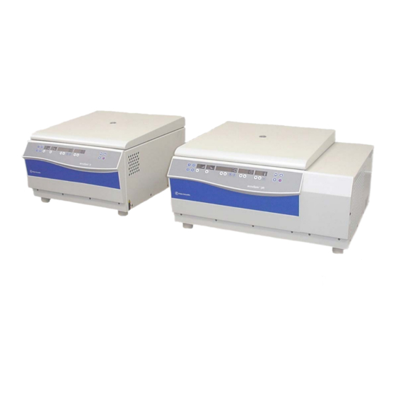
- Page 1 accuSpin™ 3 / 3R OPERATING INSTRUCTIONS...
- Page 2 How to use this manual Use this manual to get acquainted with your centri- fuge and its accessories. The manual helps you to avoid inappropriate han- Overleaf you will find a graphic dling. Make sure to keep it always close to the centri- representation of the control panel fuge.
- Page 3 acceleration deceleration (only for instruments with refrigeration unit) profiles profiles temperature run time Quick run speed/RCF program selection open lid stop start rpm/RCF pre-temperature-regulation Bucket selection switch key "set" keys "set" keys display Before switching on the centrifuge please read this manual The mains switch is located on the right-hand side panel.
- Page 4 Control panel of the accuSpin™ 3 / 3R Keys start : normal start of the centrifuge Display panels stop : manual stop of a run open lid: open lid (possible only with the instrument Program selection switched on) Key 1 - 4 : store or recall programs.
-
Page 5: Table Of Contents
Contents Contents For your safety..........3 Operation ..........29 Proper use..............3 Switching on the centrifuge ........29 Improper use ............3 Actuating the lid............29 Centrifuging hazardous materials ......3 Opening the lid ........... 29 Handling the centrifuge ..........4 Closing the lid ............. - Page 6 Emergency lid release..........49 Stopping the centrifuge .......... 41 Error troubleshooting..........51 Stopping with preset run time ......41 Contacting Fisher Scientific Service..... 60 Stopping with continuous operation ....41 Technical Data .......... 61 Temperature control during standby ...... 41 Working with programs...........
-
Page 7: For Your Safety
For your safety For your safety Proper use Fisher Scientific centrifuges are manufactured accord- The centrifuge is designed to separate liquid- ing to current technical standards and regulations. suspended materials having different densities and Nonetheless, centrifuges may pose danger to individu-... -
Page 8: Handling The Centrifuge
• Changes in mechanical or electrical components of protective tubes. the centrifuge may be carried out only by individuals authorized by Fisher Scientific Handling the centrifuge • Use only original accessories for the centrifuge. The only exception are common glass or plastic centri- fuge tubes, if they are approved for the rotor speed and RCF values. -
Page 9: Conformity To Current Standards
For your safety Conformity to current standards Safety instructions in this manual This symbol denotes potential hazards to Fisher Scientific centrifuges are manufactured and persons. tested according to the following standards and regula- tions: This symbol denotes potential damage to... - Page 10 For your safety Notes...
-
Page 11: The Accuspin™ 3 / 3R
™ Description of the accuSpin The accuSpin™ 3 / 3R Description The figure below shows a accuSpin™ 3R with the lid The accuSpin™ 3R is a general-purpose tabletop centrifuge for biotechnological and pharmaceutic re- open and a swinging bucket rotor installed. search that moves high capacity centrifugation onto the fast track. -
Page 12: Safety Systems
Description of the accuSpin ™ Safety systems Parts supplied The accuSpin™ is equipped with a number of safety Accessories supplied with the centrifuge are: systems: − power cord • Housing and lid is constructed of 8 mm steel. • Lid with window −... -
Page 13: Function And Features
™ Description of the accuSpin Function and features Basic unit/ function Description / feature Cabinet / frame galvanized steel Chamber stainless steel Drive Brushless induction drive Key pad and display key pad and display elements covered by an easy-care continues surface Control Microprocessor driven by "Easycontrol II"... - Page 14 Description of the accuSpin ™ The Easycontrol user interface Function Feature Program memory keys freely programmable Acceleration / deceleration profile 1 = slowest, ... 9 = fastest acceleration / deceleration curve Setting speed by rpm adjustable from 300 rpm to 15 000 rpm, in 10 rpm increments RCF selection upon activation of RCF switch , the RCF value can then be entered Time selection...
- Page 15 ™ Description of the accuSpin Function Feature Lid opening automatic unlocking via ”Open lid“ key ( (unlocking in case of power failure: see chapter ”Troubleshooting“) Start start key ( Stop stop key ( "Quick Run“ mode pressing the "Quick Run“ key ( ) activates maximum acceleration up to the maximum permissible speed of rotor;...
- Page 16 Description of the accuSpin ™ Notes...
-
Page 17: Before Use
Before use Before use The centrifuge can be damaged by Centrifuge transport and installation jolting during the transport! After opening the box remove the protective materials. Transport the centrifuge only in the upright position using proper con- tainment and secure it properly. When transporting centrifuge,... -
Page 18: Main Connection
Before use • The centrifuge must be protected from heat and Main connection direct sunlight. Connect the centrifuge only to an grounded main • The location must be well ventilated at all times. power supply. Make sure that the power cord is com- patible with the safety regulations valid, and that your main voltage and frequency correspond to the specifi- UV rays reduce the durability of... -
Page 19: Rotors And Accessories
Rotors and accessories Rotors and accessories A rotor is not included as part of a accuSpin™ 3 or 3R centrifuge. In addition, there are adapters and reduction sleeves for a variety of commercially available tubes and bottles. Please consult our sales documentation for a com- plete collection of accessories including technical data and order numbers. - Page 20 Rotors and accessories...
-
Page 21: Rotors For The Accuspin™ 3
Rotors and accessories Rotors for the accuSpin™ 3 Table 1: (differences of 230V instruments are shown in parentheses) Rotor designation Swinging Bucket Rotor 7500 4393 With bucket Round bucket Rectangular bucket Carrier for 750 ml 250 ml microplates Order no. 7500 4394 7500 4395 7500 4396... -
Page 22: Rotors For The Accuspin™ 3R
Rotors and accessories Rotors for the accuSpin™ 3R Table 2: (differences of 230V instruments are shown in parentheses) Rotor designation Swinging Bucket Rotor 7500 4393 Round buckets Rectangular buckets Carrier for With bucket 750 ml 250 ml microplates Order no. 7500 4394 7500 4395 7500 4396... - Page 23 Rotors and accessories Table 2: (differences of 230V instruments are shown in parentheses) Micro Liter Rotor Rotor designation 24 x 2.0 ml Order no. 7500 3337 Maximum permissible load [ g ] 24 x 4 Maximum speed n [ rpm ] 15 000 Maximum RCF value at n 21 885...
- Page 24 Rotors and accessories Adapter Table 3: Adapter (1) * max. tube length with aerosol-tight cap max. tube Adapter and accessories for dimensions tubes color order no. d x length / * diameter round buckets 7500 4394 [ mm ] [ mm ] rotor ®...
- Page 25 Rotors and accessories Table 3: Adapter (2) * max. tube length with aerosol-tight cap max. tube Adapter and accessories for dimensions tubes color order no. d x length / * diameter rectangular buckets 7500 4395 [ mm ] [ mm ] rotor ®...
- Page 26 Rotors and accessories Table 3: Adapter (3) Adapter for max. tube dimensions tube capacity number color order no. Micro Liter Rotor 7500 3337 x length [ mm ] [ ml ] per set Reduction sleeve PCR 6.2 x 20 grey 7600 3750 Reduction sleeve 8 x 43.5...
-
Page 27: Handling The Rotor
Rotors and accessories Handling the rotor Swinging Bucket Rotor 7500 4393 On swinging bucket rotors, at regular inter- vals, apply a light coating of lubricant to the rotor body trunnion pins and to the corre- sponding mating surfaces on the buckets! Lubricant 7000 6692 is supplied with the centrifuge. - Page 28 Rotors and accessories Handling microplates Remove the microplate holder from carrier to load and unload the microplate carrier 7500 6449. Make sure, before loading, that the rubber bottom is placed in the cut-outs of the bottom of plate carrier. Deepwell plates can also be inserted in the carrier without using plate holder.
-
Page 29: Aerosol-Tight Operation
Rotors and accessories Aerosol-tight operation Use the special lubricant 7600 3500 only to grease the seals ! Aerosol-tight rotors and tubes are only to be opened in an approved safety Spare parts are delivered with the rotor or may be or- work bench when centrifuging danger- dered separately. - Page 30 Rotors and accessories Micro Liter Rotor 24 x 2.0 ml Closing the aerosol-tight bio-containment Attention : After greasing the seal, turn the cover until it sits lightly on the bucket. Please check that your sample containers are suitable for the centrifugal application desired. To achieve uniform seal, turn the cover clockwise by 1½...
-
Page 31: Checking Of Aerosol-Tight Bio-Containment
Rotors and accessories Checking of aerosol-tight bio-containment As a quick test there is the possibility to check the aerosol-tight buckets and fixed angle rotors according The checking of the rotor type and bucket was done to the following procedure: according to the dynamic microbiological test proce- •... - Page 32 Rotors and accessories Notes...
-
Page 33: Operation
Operation Operation Switching on the centrifuge Locate the main power switch on the right-hand side of the front panel, and set it to the ON (I) position. For a couple of seconds the following reading appears in the Actuating the lid control panel: Opening the lid Press the "open lid"... -
Page 34: Installing The Rotor
Operation 4. The rotor must glide freely down the collet chuck Installing the rotor until it hits the lower stop. 5. If you have positioned the rotor correctly, you can Improper or improperly combined tighten the collet chuck easily using the socket accessories may cause severe dam- wrench supplied. -
Page 35: Loading The Rotor
Operation maximum permissible load Loading the rotor ∗ perm actual load Maximum loading = permissible speed perm Overloading can result in destruction = maximum speed and severe damage to the centrifuge. Filling the centrifuge tubes The accuSpin™ can reach high rotational speeds im- Check carefully whether your tubes plying enormous centrifugal force. -
Page 36: Maximum Permissible Load Difference
Operation Because higher difference Inserting the centrifuge tubes radii (r ) the pressure of liquid column to the tube bottom is appreciably higher and strongly The rotor must be loaded symmetri- pended on filling. cally. Failure to do so can cause rotor Plastic tubes and bottles –... - Page 37 Operation Swinging bucket rotors: Improper loading These examples are to be applied to the other rotors in an analogous manner! Proper loading...
- Page 38 Operation...
-
Page 39: Entering Parameters
Operation Entering parameters Bucket selection for swinging bucket rotors Deceleration curves When running a swinging bucket rotor, the automatic The accuSpin™ offers 9 acceleration and deceleration rotor identification feature will recognize the rotor body profiles for optimal centrifuging samples and gradients. and not determine which bucket or carrier is installed. -
Page 40: Selecting Speed
Operation Selecting speed For faster operation, you may shift the flash- The centrifuge speed can be set to a minimum of 300 ing cursor in the speed/RCF and the run rpm and to a maximum of 4150 rpm (depending on the time panels: just press both rotor). -
Page 41: More About The Rcf Value
Operation More about the RCF value Selecting run time The relative centrifugal force (RCF) is given in multi- There are two time modes: standard and extended. ples of the earth gravity g. It is a dimensionless number In the standard time mode you can select a run time that allows one to compare the efficiency of separation between 1 min and 9 h 59 min or continuous operation or sedimentation of diverse instruments, since it is... -
Page 42: Continuous Operation
Operation If you keep the selected key pressed, the dis- Extended time mode play changes at first slowly and after a few You can optionally switch to the extended time mode. seconds at an accelerated pace. To switch it on or off press the program selection key Release the key as soon as you have reached and start the centrifuge simultaneously. -
Page 43: Selecting The Temperature
Operation The temperature display flashes for a number of sec- Selecting the temperature onds, then changes to the current value display. The You can select the temperature in the range of -9 °C to temperature set point is now stored. +40 °C. -
Page 44: Starting The Centrifuge
Operation Starting the centrifuge Imbalance display Once the rotor is properly installed, the main switch If rotor imbalance is detected, shortly after the rotor turned on and the lid is closed, you can start the centri- reaches 300 rpm, the message "bAL "... -
Page 45: Stopping The Centrifuge
Operation Stopping the centrifuge Temperature control during standby Stopping with preset run time Temperature control becomes active once the rotor has been identified. This is the case after a centrifuga- Normally the run time has been selected, and all you tion run exceeding 300 rpm. -
Page 46: Working With Programs
Operation Centrifuging with a program Working with programs After closing the centrifuge lid, call the desired program The 4 program selection keys offer the option of storing memory number using the program selection key and and recalling the individual centrifugation processes. press the start key If the rotor is started with a program the speed or RCF set point value of which exceeds the permissible one... -
Page 47: Quick Run
Operation ”Quick Run” Removing the rotor For short-term operation the accuSpin™ is equipped 1. Open the centrifuge lid. with a "Quick Run" function 2. Remove the rotor cover. Short-term centrifugation is started by pressing the 3. Unscrew the clamping sleeve counterclockwise "quick run"... -
Page 48: Audible Alarm
Operation Audible alarm Turning the centrifuge off Accompanying all error messages, a warning signal is By switching the main switch into "0“ position the cen- given out which only is silenced upon pressing any key. trifuge is turned off. As an option, you can also have the end of a run sig- The main power switch should be turned off naled acoustically. -
Page 49: Maintenance And Care
Maintenance and care Maintenance and care Cleaning Maintenance to be performed by the Pull mains plug before cleaning the customer instrument! For the protection of persons, environment and mate- rial you are obliged to clean the centrifuge regularly Clean the casing, the rotor chamber, the rotor and the and to disinfect it if necessary. -
Page 50: Disinfection
Maintenance and care Disinfection If a centrifuge tube containing infectious material leaks During cleaning liquids and espe- during a run, you have to disinfect the centrifuge im- cially organic solvents should not mediately. come into contact with the drive shaft and the ball bearing. Organic solvents may decompose Infectious material could enter the centri- the lubricant of the motor bearing. - Page 51 Maintenance and care Rotor and rotor chamber must be treated with a neu- 4. Remove the centrifuge tubes and adapters, and tral, universal disinfectant. Best suited for this purpose disinfect them or dispose of them as necessary. are disinfectant sprays, ensuring that all rotor and ac- 5.
-
Page 52: Decontamination
Maintenance and care Decontamination For general radioactive decontamination, use a solu- Chemical additives to the steam are not tion of equal parts of 70% ethanol, 10% SDS and wa- permitted. ter. Follow this with ethanol rinses, then de-ionized water rinses, and dry with a soft absorbent cloth. Dis- pose of all washing solutions in appropriate radioactive Never exceed the maximum permis- waste containers! -
Page 53: Troubleshooting
Troubleshooting Troubleshooting Proceed as follows: 1. Make sure that the rotor is at a stand still Emergency lid release (observe through window in the cover). In case of a power failure the lid could not be opened normally using the electrical lid unlocking mechanism During a power failure it is impossible To permit unloading in this case, the centrifuge is to lock the lid once the emergency lid... - Page 54 Troubleshooting 4. After finished, push the cord back into the instru- ment and reinserting the plastic plug. Once the power is restored, you can connect the in- strument to the main supply and turn it on. Following the self test of the centrifuge, the lid may be closed and locked with the motor.
-
Page 55: Error Troubleshooting
Troubleshooting Error troubleshooting If problems other than those described in the following tables arise, you must contact Fisher Scientific service. Error Symptom Possible causes and corrective measures Displays remain dark The drive stops. Mains power failure or not connected The rotor stops without 1. - Page 56 Troubleshooting Error Symptom Possible causes and corrective measures – Centrifuge is exceptionally Imbalance. noisy. 1. Stop the centrifuge by pressing the "stop" key, in case of emergency, unplug mains power cord. 2. Wait until the centrifuge comes to a complete stop. 3.
- Page 57 Troubleshooting Error Symptom Possible causes and corrective measures Message "rotor" appears Rotor decelerates with Set speed exceeds permissible maximum speed for the delayed deceleration. rotor. (The same holds for RCF setting) in display. A) For about 15 sec. the display shows alternately "rotor" and the maximum permissible speed or RCF for the installed, after the rotor identification.
- Page 58 Troubleshooting Error Symptom Possible causes and corrective measures E-01 Rotor stops without Internal program error. deceleration to standstill. Switch the instrument off and on again. If the error persists, Instrument cannot be contact service. E-13 operated. E-14 Overtemperature in the centrifuge tank. Rotor stops with deceleration to standstill.
- Page 59 Troubleshooting Error Symptom Possible causes and corrective measures E-19 Instrument stops with No rotor present or rotor identification impossible. deceleration to standstill A) Check whether a certified rotor is inserted. after short starting-up. B) Please take care of the readability of the inscription of the swinging bucket rotor cross installed.
- Page 60 Troubleshooting Error Symptom Possible causes and corrective measures E-21 Instrument does not start or No rotor present or rotor identification impossible brakes to standstill. A) Check whether a certified rotor is inserted. B) Following a brief power failure, the rotor could not be identified.
- Page 61 Troubleshooting Error Symptom Possible causes and corrective measures E-29 Motor does not start. Motor or rotor blocked. 1. Switch instrument off and on again using the main switch. 2. Open the lid. 3. Check whether the rotor can turn freely. If you cannot clear the malfunction, contact service.
- Page 62 Troubleshooting Error Symptom Possible causes and corrective measures E-33 Rotor stops without brake Overpressure in the refrigeration system to standstill or does not Turn instrument off and pull main plug. start. Check and clean ventilation slots if necessary. After about 60 min you can restart the instrument. Observe the max.
- Page 63 Troubleshooting Error Symptom Possible causes and corrective measures E-40 Rotor stops without brake Acceleration of rotor too slow to standstill. Open the lid and check the load! Instrument cannot be Significant imbalance caused by missing bucket operated. Tubes or adapter do not fit (rotor is rubbing the chamber or the cover) Micro plates carriers on the motor cover If the error persists, contact service.
-
Page 64: Contacting Fisher Scientific Service
Troubleshooting Subsequently, the following readings will be dis- Contacting Fisher Scientific Service played for 5 seconds each: Should you require our Service, please advise us of the (numbers are examples) catalog and serial number of your instrument. You will... -
Page 65: Technical Data
45.8 kNm (33 780 ft.lb) accuSpin 3R 54.8 kNm (40 418 ft.lb) noise at maximum speed accuSpin 3 < 66 dB (A) accuSpin 3R < 55 dB (A) (sound pressure level of emission according to DIN EN ISO 11 201) Temperature set range -9 °C to +40 °C... - Page 66 Technical Data Features specification Dimension (H x W x D) accuSpin 3 362 mm x 551 mm x 666 mm ( 14.3 x 21.7 x 26.2 inches ) 362 mm x 733 mm x 666 mm ( 14.3 x 28.7 x 26.2 inches )
-
Page 67: Electrical Connections / Fuses
Power Fuse protection of Fuse current consumption instrument protection of building safety fuse * thermic excess current release accuSpin 3 120 V 60 Hz 10,2 A 900 W 15 A 15 AT 7500 4391 accuSpin 3 230 V 50/60 Hz 8.6 A... - Page 68 Notes...
-
Page 69: Appendix
Appendix Acceleration and deceleration profiles On the following pages you find acceleration and deceleration profiles for each rotor type respectively. - Page 70 Acceleration profiles Swinging bucket rotor with rectangular buckets 7500 4395 time [s]...
- Page 71 Deceleration profiles Swinging bucket rotor with rectangular buckets 7500 4395 time [s]...
- Page 72 Acceleration profiles Micro liter Rotor 7500 3337 time [s]...
- Page 73 Deceleration profiles Micro liter Rotor 7500 3337 time [s]...
-
Page 74: Speed/Rcf Diagrams
Speed/RCF diagrams = max. speed Speed/RCF diagram Swinging Bucket Rotor 7500 4393 10000 Round bucket 1000 Rectangular bucket = 4150 rpm = 3696 Micro plate swing = 4150 rpm = 3061 1000 10000 speed (rpm) - Page 75 Speed/RCF diagram Micro liter Rotor 7500 3337 100000 = 15 000 rpm RCF (r ) = 21 885 = 8.7 cm 10000 = 5.9 cm 1000 1000 10000 100000 speed (rpm)
-
Page 77: Index
Index acceleration and deceleration curves · 65 centrifuge exceptionally noisy · 52 acceleration profiles · 7 Centrifuge transport and installation · 13 Acceleration/decelaration profile · 10 Centrifuging with a program · 42 actual values · 36 changing settings adapter · 20 during run ·... - Page 78 deceleration profiles · 7 decontamination · 46 Description · 7 filling the centrifuge tubes · 31 Description / feature · 9 fixed run time · 37 Diagnostic messages · 11 disinfectant · 47 disinfection · 4 procedure · 47 disinfection with bleaching lye · 47 general view ·...
- Page 79 imbalance detection · 8 maximum permissible RCF · 40 indoor use · 13 maximum permissible speed · 40 infectious material Maximum RCF value · 17 precautions in case of tube breakage · 46 maximum sample density · 3 Inserting the centrifuge tubes · 32 microtest plates ·...
- Page 80 Program memory keys · 10 remain dark · 51 program storing · 42 rotor cover · 30 protective tubes rotor identification · 8 for corrosive substances · 4 rotor identification · 36 and RCF display · 36 Rotor program for the Multifuge · 17 rotors approved ·...
- Page 81 setting speed · 36 settings Technical Data · 61 change during run · 40 test Short time centrifugation · 43 aerosol-tightness · 27 short-time operation · 43 The printed documents consist of the delivery notes and signal · 44 this Manual · 8 software check time internal ·...
- Page 82 For Ordering or Technical Information In the interest of continuous product development, we reserve the right to make changes without express notice. ©2003 Fisher Scientific All Rights Reserved. Printed in Germany 20057884 accuSpin 3-3R _US Rev. 03/04...
Need help?
Do you have a question about the accuSpin 3 and is the answer not in the manual?
Questions and answers