
Related Manuals for Fisher Scientific 282A


Summary of Contents for Fisher Scientific 282A
- Page 1 Instructions Fisher Isotemp Model 282A Vacuum Oven Catalog No. 13-262-52 & 53 Manual PN 52063 (REV H) Published 3/02 2000 Park Lane Pittsburgh, PA 15275 (412) 490-8300...
- Page 2 THE INSTRUMENT Performance Characteristics CONTROLS, INDICATORS AND CONNECTORS CONNECTORS AND VALVES Site Requirements Installation OPERATION Main Controller Menu Table 2: Default Menu (Menu 1) Key Entry Table 3: Adjust Temperature Offset (Menu 2) Key Entry Table 4: Adjust Barometric Pressure Offset (Menu 3) Key Entry Table 5: Set Time and Day (Menu 4) Key Entry...
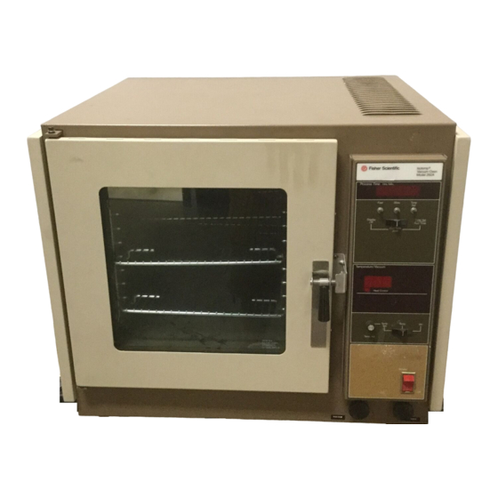
- Page 3 THE INSTRUMENT The Fisher Isotemp® Vacuum Oven, Model 282A, is designed to operate with reduced pressures and/or with inert atmospheres. As such, it is equipped with separate vacuum and gas ports--each has its own control valve. Additionally, a special digital readout display indicates time of day, chamber temperature, pressure and schedules for programmed oven operation.
-
Page 4: Safety Precautions
Warranty Card CONTROLS, INDICATORS AND CONNECTORS Before putting the Model 282A into operation, the user should become thoroughly familiar with the location and function of all controls, indicators, and connectors. Most are clearly labeled and located on or below the front panel, with the exception of the two (PURGE and VACUUM) hose connectors, which are located on the lower, right side of the oven. -
Page 5: Led Indicators
Decrease: Decrements values to be selected for each parameter. CONNECTORS AND VALVES POWER SWITCH: A rocker type switch that controls all power to the Model 282A Vacuum Oven. VACUUM CONTROL Valve: A forged body, shut-off valve used to open and close the connection to an auxiliary vacuum pump. - Page 6 Calibration Jumper Pin (JP4): Group of four pins located in the center of the rear of the control board. The lower two pins when jumped enable calibration mode. See Figure 2 for controller rear view.
-
Page 7: Installation And Assembly
Unit must be calibrated to clear INSTALLATION AND ASSEMBLY The Model 282A is shipped assembled and ready for ope ration. However, before installing the oven, the operating site should be prepared to meet necessary requirements. Additionally, a few assembly procedures must be performed before the oven can be safely and properly operated. - Page 8 For installations that may use a tank atmosphere, check that site facilities and tank equipment are in compliance with OSHA requirements for handling compressed gas. Responsible personnel must also be thoroughly knowledgeable in the use, storage, and handling of compressed gases. Fisher Scientific carries a complete line of accessory equipment for gas cylinders.
-
Page 9: Operation
After installing connecting tubing, check that the PURGE CONTROL valve on the Model 282 is closed (full clockwise position) then open the regulator flow control valve to pressurize the line. At this point, check all connections for leaks using an ordinary soapy water solution. Check data plate and plug line cord into a suitable power receptacle OPERATION Main Controller Menu... - Page 10 Press SET or wait 2 Unit returns to the default menu. seconds Table 5: Set Time and Day (Menu 4) Step Key Entry Action Display Press MENU until TSET Unit enters set time and day mode and the current hour and 08:00 AM •...
- Page 11 Press MENU to exit Unit displays COPY/NO. This option will copy 8 steps forward to each day through the end of the week. Use the UP/DOWN keys to adjust prompt to Y or N. Establishing Operating Conditions Establishing the operating conditions consists of setting the desired temperature program and establishing the desired environmental conditions, e.g., vacuum, inert gas atmosphere, or both.
- Page 12 CAUTION: The maximum allowable current in the auxiliary circuit is 6 amps. See page 2 for contact ratings before applying power. Connect the vacuum hose to the Vacuum Inlet Port on the side of the oven and open the Vacuum valve. Close the door and the Purge Inlet Port by turning Purge valve clockwise completely.
-
Page 13: Programming The Oven
Temperature/Pressure Offsets When the oven reaches a stable operating condition, the display temperature should indicate the actual center chamber temperature (+/- 2.0°C). In the event a more accurate display reading is needed, the offset parameter, located in the MAIN MENU, can compensate for the error. To enter an offset value, press the MENU key until the upper display window shows ADJT (adjust temperature) then press UP/DOWN arrow keys to enter an offset for the display temperature. - Page 14 Repeat Tuesday. Thursday: Repeat Monday. Friday: Repeat Monday. Using the information on page 8, MENU6, the program could be set up as shown on page 12. SAMPLE PROGRAM ARRAY STEPS MONDAY TUESDAY WEDNESDAY THURSDAY FRIDAY SATURDAY SUNDAY Temp: 100°C Temp: 100°C Temp: 100°C Temp: 100°C Temp: 100°C...
-
Page 15: Calibration Procedures
OFF, then press SET or wait 2 seconds for the program to stop automatically. CALIBRATION PROCEDURES The Model 282A Isotemp® Vacuum Oven is carefully calibrated before leaving the factory. However, re-calibration will be necessary when component parts are repaired or replaced. This is especially true regarding the vacuum readout system. - Page 16 In fact, measurements outside this range should be suspect. Slight variations will exist usually because of pressure variations due to weather conditions. Therefore, the most accurate way to calibrate the Model 282A vacuum readout system is to first obtain the atmospheric pressure using one of the methods above.
- Page 17 Mcleod Vacuum Gauge FSCO 10-269-27 To Vacuum Sensor Press the SET key to enable vacuum calibration. The upper display will show PRSR with the AM LED flashing. The lower display will indicate 29.0 in Hg. Use the UP/DOWN arrow keys to set the displayed pressure to match the atmospheric pressure. Press the SET key again to enter the value.
-
Page 18: Maintenance
(see step #5 under Calibration Mode). MAINTENANCE The Model 282A is constructed and finished with materials that provide long maintenance-free service. All that is normally required is a routine cleaning of the exterior surfaces, oven shelf, and oven floor. Use a mild detergent for this purpose. - Page 19 Door Alignment Procedure A good seal around the door is critical, particularly when operating the oven with a vacuum environment. Therefore, the following procedure should be performed carefully. Refer to the illustrations shown in Figure 6 and perform the following. Loosen, but do not remove, the four (two in both the top and bottom hinge) screws securing the door hinges.
- Page 20 Figure 6.1 – 6.6: Door Alignment...
- Page 22 It should be noted that, because of the very low watt density of the heater elements, an almost indefinite life is expected. Because the Model 282A is equipped with self-diagnostic features, the service recommendations here are limited to the Trouble Analysis Chart shown below which incorporates these features. To use this chart effectively, select the Symptom category(s) that best describes the observable malfunction, in particular the error codes.
-
Page 23: Replacement Parts
Symptom Probable Cause Corrective Action vacuum sensor disconnected. Door improperly aligned. Realign door following instruction given in this manual. REPLACEMENT PARTS The replacement parts and their corresponding numbers are provided in this section. Note that parts information is only valid at the publication date (see front cover of this manual), and subsequent revisions may have occurred after publication. - Page 25 Schematics Figure 7: 115V Schematic Figure 8: 230V Schematic...
Need help?
Do you have a question about the 282A and is the answer not in the manual?
Questions and answers