Table of Contents
Advertisement
Advertisement
Table of Contents

Related Manuals for Kubota KX 016-4


Summary of Contents for Kubota KX 016-4
- Page 1 1BAAACDAP2310...
- Page 2 ABBREVIATION LIST Abbreviations Definitions American Petroleum Institute ASTM American Society for Testing and Materials, USA CECE Committee for European Construction Equipment German Institute for Standards, Federal Republic of Germany European Standard Operator Protective Guards FRONT "Front" means the front view towards the boom and dozer High speed International Standardization Organization Japanese Industrial Standard...
- Page 3 GENERAL SYMBOLS The instruments and operation elements have been marked with a series of symbols in order to simplify the opera- tion of your excavator. These symbols are listed below with the respective descriptions. Safety alert Symbol Boom swing (Left) Warning lamp “Fuel level too low”...
- Page 4 FOREWORD You are now the proud owner of a KUBOTA excavator. This excavator is a product of KUBOTA quality engineering and manufacturing. It is made of the fine materials and under rigid quality control systems. It will give you long, satisfactory service.
-
Page 5: Table Of Contents
CONTENTS SAFE OPERATION ....................1 DANGER, WARNING AND CAUTION LABELS ............8 CARE OF DANGER, WARNING AND CAUTION LABELS ........13 DEALER SERVICE...................... 1 TECHNICAL DATA...................... 2 DESCRIPTION OF MACHINE PARTS................ 3 INSTRUMENT PANEL AND CONTROL ELEMENTS..........4 CHECKS BEFORE START ..................7 DAILY CHECKS....................... - Page 6 CONTENTS Pivot Turn ........................23 Spin Turn ........................24 UP AND DOWNHILL DRIVING................25 TWO PATTERN SELECTION SYSTEM(TPSS) ............ 26 Pattern Change....................... 26 OPERATION OF THE BOOM................27 OPERATION OF THE ARM................... 27 OPERATION OF THE BUCKET ................28 SWIVEL(UNIT SWING)OPERATION ..............28 BOOM SWING OPERATION.................
- Page 7 Fuse Capacities and Circuits ..................58 Auxiliary Electric ......................59 Slow Blow Fuse ......................59 TROUBLESHOOTING....................60 KUBOTA I.C.S. NAVIGATION LIST OF MESSAGES ........... 62 OPERATION UNDER COLD WEATHER CONDITIONS .......... 67 PREPARATION FOR OPERATION IN COLD WEATHER ........67 PROCEDURE AFTER DONE WORK..............67 LONG STORAGE ......................
-
Page 9: Safe Operation
4. For your safety, a ROPS/OPG (Roll-Over Protective Structure, Operator Protective Guards(top guard).) accident. with a seat belt is installed by KUBOTA. Always use Read and understand this manual carefully, before the seat belt when the machine is equipped with a operating the excavator. - Page 10 SAFE OPERATION 8. Study control lever pattern A and pattern B. Then choose the one which is most familiar. Familiarize yourself with the pattern selected by operating the unit slowly and at low engine speed. A Before changing the pattern, be sure to stop the engine.
- Page 11 5. Do not operate or idle engine in a non-ventilated area. dust and grass can cause fires, accidents or injuries. Carbon monoxide gas is colorless, odorless, and 16. Use only KUBOTA authorized attachments. deadly. 17. Before starting the excavator, be confirm that the excavator has been filled with fuel, lubricated, greased and undergone any required maintenance work.
- Page 12 SAFE OPERATION 7. When operating, keep hands and body inside of the ROPS / OPG protective envelope. AFTER OPERATION Do not touch or depress the control levers or the pedals from outside the cab while the engine is Before leaving the machine, running.
- Page 13 SAFE OPERATION 6. When towing the excavator or pulling a load, the load must be less than the strength of the towing line SAFE LOADING AND TRANSPORT OF attached to excavator. The towing eye should not be THE EXCAVATOR used for tie down or lifting of the machine. Max.
- Page 14 KUBOTA dealer where the machine was purchased, or competent service shop. The assembly must be done according to the KUBOTA work shop manual (W.S.M.) for the product involved. 17. When lifting the machine itself with an attachment, place a safety block or safety post to prevent the machine from rolling over.
- Page 15 SAFE OPERATION 18. Inspect ROPS / OPG for damage and if damage is found contact your KUBOTA dealer for repair. 19. KUBOTA does asbestos containing components and recommends against the use of such components. Components containing asbestos should be handled in accordance with applicable regulations and industry practice.
- Page 16 SAFE OPERATION DANGER, WARNING AND CAUTION LABELS...
- Page 17 SAFE OPERATION...
- Page 18 SAFE OPERATION...
- Page 19 SAFE OPERATION...
- Page 20 SAFE OPERATION...
-
Page 21: Care Of Danger, Warning And Caution Labels
2. Clean danger, warning and caution labels with soap and water, dry with a soft cloth. 3. Replace damaged or missing danger, warning and caution labels with new labels from your KUBOTA dealer. 4. If a component with danger, warning and caution label(s) affixed is replaced with new part, make sure new label(s) is (are) attached in the same location(s) as the replaced component. -
Page 23: Dealer Service
DEALER SERVICE DEALER SERVICE Your KUBOTA dealer is always ready to help so that your excavator offers the best performance. After having carefully read this manual, you will realize that much of the routine maintenance can be done by yourself. Your KUBOTA dealer is responsible for servicing and the delivery of spare parts. -
Page 24: Technical Data
TECHNICAL DATA TECHNICAL DATA KUBOTA EXCAVATOR Model name KX016-4 KX018-4 Type canopy Mass (without operator) 1490 1620 Volume (CECE) m 0.035 0.040 Standard Width [with side cutter] 402 [422] 450 [474] bucket Weight 32.5 33.5 Type 3 cylinder - diesel engine water cooled... -
Page 25: Description Of Machine Parts
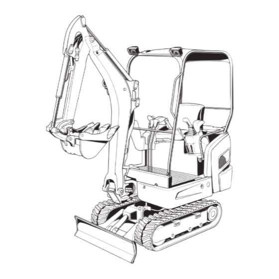
DESCRIPTION OF MACHINE PARTS DESCRIPTION OF MACHINE PARTS DEPICTED CONTENTS (1) Arm (2) Bucket cylinder (3) Bucket link 2 and 3 (4) Bucket link 1 (5) Bucket (6) Boom cylinder (7) Swing bracket (8) Track (9) Dozer blade (10) Boom (11) Arm cylinder (12) Canopy(Rops / OPG Top Guard) (13) Working light... -
Page 26: Instrument Panel And Control Elements
INSTRUMENT PANEL AND CONTROL ELEMENTS INSTRUMENT PANEL AND CONTROL ELEMENTS B Switches DEPICTED CONTENTS (1) Horn switch (2) Travel speed switch (3) Starter switch (4) Working light switch (5) Beacon switch (6) Engine stop knob (7) User setting switch (switch 2) (8) Display selector switch (switch 3) - Page 27 INSTRUMENT PANEL AND CONTROL ELEMENTS B Control Pedals and Levers DEPICTED CONTENTS (1) Throttle lever (2) Drive lever (left) (3) Drive lever (right) (4) Attachment control lever (left) (5) Attachment control lever (right) (6) Dozer control lever (7) AUX port pedal (8) Boom swing pedal (9) Lock lever (Unload lever)* (10) Track width change lever...
- Page 28 INSTRUMENT PANEL AND CONTROL ELEMENTS B Instrument Panel DEPICTED CONTENTS (1) Speed indicator lamp (8) Engine oil pressure warning lamp (2) Insert key lamp (9) Battery charge lamp (3) Pull out key lamp (10) Coolant temperature warning lamp (4) Periodic check lamp (11) Warning lamp (5) Clock setting request lamp (12) Fuel gauge...
-
Page 29: Checks Before Start
CHECKS BEFORE START CHECKS BEFORE START DAILY CHECKS BWorking Light Switch In order to avoid damage, it is important to check the To turn on the working light, set the starter switch to the condition of the excavator before starting. "RUN"... -
Page 30: Danger, Warning And Caution Labels
OPERATION OF THE ENGINE OPERATION OF THE ENGINE To avoid personal injury: A Read "SAFE OPERATION" at the beginning of this operator's manual. A Obey the danger, warning and caution labels on the excavator. A To avoid danger exhaust fume poisoning, do not operate the machine in a closed building without proper ventilation. -
Page 31: Display Selector Switch
OPERATION OF THE ENGINE BDisplay Selector Switch C Setting the clock [Selecting the clock setting mode] Press the display selector switch. The electronic meter's 1. Press the user setting switch (switch 2). LCD display will change from one indication mode to the 2. - Page 32 OPERATION OF THE ENGINE [Setting the month] [Setting the hour] Press switch 2 and the numeric setting will be smaller. Press switch 2 and the numeric setting will be smaller. Press switch 3 and the numeric setting will be larger. Press switch 3 and the numeric setting will be larger.
-
Page 33: Battery Charge Lamp
OPERATION OF THE ENGINE BBattery Charge Lamp BGlow Lamp This warning lamp lights up if the charging system fails With the starter key at the "RUN" position, the engine's with the engine running. When the starter switch is turned preheat status is indicated. to "RUN"... -
Page 34: Lcd Display For Normal Operation
OPERATION OF THE ENGINE C Coolant Temperature Gauge BLCD Display for Normal Operation C Fuel gauge To avoid personal injury: A Do not open the radiator cap during or just after operation. Hot coolant may gush out and scald To avoid personal injury: you. -
Page 35: Lcd Display For Warning
A Warnings and errors are displayed and an alarm buzzer beeps. A Let your KUBOTA dealer inform you of details concerning care and maintenance. (1) Engine oil pressure lamp (2) Warning lamp (red) -
Page 36: Checkpoints After Starting The Engine
A In these cases, the excavator must be checked and another 10 minutes or while steam is emitting. serviced by your local the KUBOTA dealer. 4. Make sure there is no hazard of getting burned. Pinpoint and remove the cause of overheat, referring to "TROUBLESHOOTING". -
Page 37: Engine Stop Knob
OPERATION OF THE ENGINE BObserve Following Guidelines when After slowing the engine to idle, turn Starting with an Auxiliary Battery the key to "STOP". 1. Bring the helping machine with the same battery voltage as near as possible to the machine. Remove the key. -
Page 38: Excavator Operation
EXCAVATOR OPERATION EXCAVATOR OPERATION RUNNING-IN OF THE NEW EXCAVATOR STARTING The operation and care of the new excavator influences Wear the seat belt. its life span. Your new excavator has been carefully checked and tested before leaving the factory. In spite of this, all movable components must run-in during the first BSeat Belt 50 work hours. - Page 39 EXCAVATOR OPERATION [KX018-4] [KX016-4] (1) Weight indicator (1) Backrest adjustment lever (2) Lever (2) Weight indicator (3) Backrest adjustment lever (3) Spring adjustment grip (4) Horizontal seat adjustment lever (4) Horizontal seat adjustment lever C Horizontal seat adjustment (seat stand-off) C Horizontal seat adjustment (seat stand-off) Pull the horizontal seat adjustment lever up and move the Pull the horizontal seat adjustment lever up and move the...
-
Page 40: Lock Lever (Unload Lever)
EXCAVATOR OPERATION BWorking Light Switch After starting the engine, bring the lock lever (unload lever) into the "Unlock" When the starter switch is in position "RUN", the light(s) position to use drive lever or control will be switched on by pressing the switch. lever for front attachments. -
Page 41: Operation Of Track Width Change
EXCAVATOR OPERATION OPERATION OF TRACK WIDTH CHANGE OPERATION OF THE DOZER 1. To raise the dozer, pull back the control lever. Pushing the control lever forward, lowers the dozer. To avoid personal injury or death: A Operate always in standard track width 1240 mm [KX016-4] / 1300 mm [KX018-4], except to pass through narrow space. -
Page 42: Adjustment Of The Dozer Width
EXCAVATOR OPERATION DRIVING BAdjustment of the Dozer Width In order to change from standard width to narrow width: 1. Pull out the locking pin (2) and rotate the extension To avoid personal injury or death: dozer (1). A Before starting the engine, make sure that no 2. - Page 43 EXCAVATOR OPERATION A Recommended technique for working on a 3. Activate the dozer control lever to raise the dozer. slope. 1. Adjust the engine speed from idling to an intermediate speed. 2. Unlock the lock levers and pull in the bucket and hold the bucket about 20 to 40cm above the ground.
-
Page 44: Drive Levers(Right,Left)
EXCAVATOR OPERATION BDrive Levers(Right,Left) BTravel Speed Switch Travel speed will increase when this switch is pushed down. Switching the dual travel speed: To avoid personal injury or death: 1. Press the travel speed switch. The buzzer beeps and A If the swing frame has been turn 180deg, i.e. the the travel speed changes from first speed to second. -
Page 45: Turns
EXCAVATOR OPERATION TURNS A Do not activate the travel speed switch when there is increased drive resistance (e.g. driving on inclines or on uneven grounds). A If the tracks are clogged with sand or gravel while To avoid personal injury: A Do not change direction on steep slopes, or the working on soft ground, lift up one track with the help of the boom, arm and bucket and let the track rotate to... -
Page 46: Spin Turn
EXCAVATOR OPERATION C Change of Direction while Stationary BSpin Turn 1. Push the left drive lever forward; When both drive levers are activated in the opposite the excavator will turn in the direction of the arrow of directions, both tracks will rotate with the same speed but the illustration below. -
Page 47: Up And Downhill Driving
While traveling uphill, keep the lower edge of the bucket approx. 20 to 40cm (8 to 16 in.) above the ground. Although the KUBOTA excavator will not slip easily because of the tracks, it is safer to let the bucket slide over the ground while traveling downhill. -
Page 48: Two Pattern Selection System(Tpss)
EXCAVATOR OPERATION TWO PATTERN SELECTION SYSTEM(TPSS) To avoid personal injury: A Study control lever pattern A and pattern B. Then choose the one which is most familiar. A Position the pattern selector lever (located under the operator's seat) in either the lower position (Pattern A) or the upper position (Pattern B). -
Page 49: Operation Of The Boom
EXCAVATOR OPERATION OPERATION OF THE BOOM OPERATION OF THE ARM To raise the boom, pull the attachment control lever back. Pull back the attachment control lever and the arm will be The boom is equipped with a cushion cylinder which helps pulled in. -
Page 50: Operation Of The Bucket
EXCAVATOR OPERATION OPERATION OF THE BUCKET SWIVEL(UNIT SWING)OPERATION To dig using the bucket, move the right attachment control lever from the neutral position, left. Moving the control lever right, moves the bucket outward and empties its To avoid personal injury: contents. -
Page 51: Boom Swing Operation
EXCAVATOR OPERATION BOOM SWING OPERATION AUXILIARY PORT OPERATION 1. Flip the pedal lock up to unlock the pedal. 2. Step on the left side of the pedal ( ) to swing the boom to the left. To avoid personal injury: 3. -
Page 52: Parking On A Slope
EXCAVATOR OPERATION IMPORTANT INFORMATION ON [KX018-4] Max. Flow Volume 27.7 EXCAVATOR OPERATION (Theoretical L/min.) (7.4) A Do not try to crush concrete or boulders using side Max. Pressure 21.6 swings with the bucket. Also avoid using side sweeps MPa (kgf/ (220) of the bucket to move earth piles. -
Page 53: Transporting The Excavator On A Vehicle
TRANSPORTING THE EXCAVATOR ON A VEHICLE TRANSPORTING THE EXCAVATOR ON A VEHICLE B Transporting on a truck To avoid personal injury or death: A No directional changes should be made when To avoid personal injury or death: the excavator is on the ramp. Should a change A After loading the machine on the truck, lower of direction be necessary, drive off the ramp the bucket and dozer onto the truck bed. - Page 54 TRANSPORTING THE EXCAVATOR ON A VEHICLE 2. Use mounting brackets to secure the ramp properly. 5. Block the tracks and cable down the excavator with Connect the ramps directly to the bed. suitable chains approved method (check appropriate state regulation). (A) 4 x H or more (1) Chain 3.
-
Page 55: Lifting Of The Excavator
LIFTING OF THE EXCAVATOR LIFTING OF THE EXCAVATOR B Lifting Procedure for the Excavator To avoid serious injury or death: A The correct instructions for safe handling are To avoid personal injury or death: described here. Read these instructions A Do not use the hooks on the roof of canopy for carefully before moving the machine. - Page 56 LIFTING OF THE EXCAVATOR 3. Tackle 1. Boom side The weights of the excavators and the recommended Hook in the steel cable with a shackle into the lifting tackle for lifting these loads are mentioned in the hole. following table. Choose components having enough strength.
-
Page 57: Maintenance
MAINTENANCE MAINTENANCE To avoid personal injury: A Before doing maintenance work on the machine, place the machine on a firm, flat and level surface, lower the attachments and dozer blade on the ground, release the cylinder pressure by actuating the levers, stop the engine, lock all control levers, remove the key and then block the tracks with the blocks. -
Page 58: Maintenance Intervals
MAINTENANCE MAINTENANCE INTERVALS Hour meter indicator Ref. Check points Measures Interval page check Daily check Coolant change every 2 years Fuel check Daily check check Daily check Engine oil change every 250 hrs check Daily check Hydraulic oil change every 1000 hrs Lubrication points Daily check Radiator and oil cooler... - Page 59 *4 Consult your local KUBOTA dealer for this service. A The items listed above (@ marked) are registered as emission related critical parts by KUBOTA in the U.S.EPA non- road emission regulation. As the engine owner, you are responsible for the performance of the required...
-
Page 60: Opening And Closing Of Parts
MAINTENANCE C How to use the funnel OPENING AND CLOSING OF PARTS This machine is provided with a funnel that is a standard BOpening and Closing of the Fuel Tank Cap accessory. When refueling the machine, remove the cap and put the 1. -
Page 61: Opening/Closing Of The Engine Hood
MAINTENANCE BWhere to keep Operator's Manual BOpening/Closing of the Engine Hood To avoid personal injury: A Do not open the engine hood with the engine running unless in an emergency. A Do not touch the exhaust muffler or the exhaust pipe; serious burns can occur. Insert the key into the key slot and turn it clockwise to open the hood. -
Page 62: Daily Checks
MAINTENANCE DAILY CHECKS BChecking Fuel Level For your own safety and to assure the long life of your machine, a careful check should be made before each operation. To avoid personal injury: BChecking Coolant Level A Stop the engine and remove the key before fuelling. -
Page 63: Checking Engine Oil Level
MAINTENANCE C Fuel level audible indication switch (when refueling) BChecking Engine Oil Level 1. With the starter key at the "OFF" position, press the the user setting switch (switch 2) or the display selector switch (switch 3), and the fuel level can be To avoid personal injury: checked with buzzer sound. -
Page 64: Checking Hydraulic Oil Level
MAINTENANCE 4. Should the oil level be too low, fill oil through the oil BChecking Hydraulic Oil Level port before starting the engine. This step is important for the protection of the hydraulic system. To avoid personal injury: A Stop the engine and remove the key before checking the oil level. -
Page 65: Lubrication Points
MAINTENANCE BLubrication Points To avoid personal injury: A First lower all attachments to the ground then stop the engine and remove the key. A While greasing, take caution not to step on the bucket teeth. A When doing excavation work water, generously grease the following points. -
Page 66: Check Fan Belt
MAINTENANCE BCheck Fan Belt BChecking and Cleaning Engine and Electrical Wiring To avoid personal injury: A Stop the engine and remove the key before checking the fan belt. To avoid personal injury: A Check the fan belt for cracks and proper A Always stop the engine and remove the key tension. -
Page 67: Regular Checks And Maintenance Work
REGULAR CHECKS AND MAINTENANCE WORK REGULAR CHECKS AND MAINTENANCE WORK BChecking Water Separator 1. Open the hood. To avoid personal injury: A Before doing maintenance work on the 2. When the separated water is being drained, the red machine, place the machine on a firm, flat and float moves upwards. -
Page 68: Battery
REGULAR CHECKS AND MAINTENANCE WORK BBattery BBattery Charging To avoid the possibility of a battery explosion: To avoid personal injury: A When the battery is being activated, hydrogen For refillable type battery, follow the instructions below. and oxygen gases in the battery are extremely A Do not use or charge the refillable type battery explosive. -
Page 69: Greasing Swing Bearing Teeth
REGULAR CHECKS AND MAINTENANCE WORK A Should the machine be used in extremely dusty areas, BGreasing Swing Bearing Teeth the air filter element must be inspected and cleaned 1. Pump grease with grease gun through the grease more frequently than in the specified maintenance nipple (at the right end side). -
Page 70: Greasing Swing Ball Bearing
REGULAR CHECKS AND MAINTENANCE WORK EVERY 250 SERVICE HOURS Do all 50 hour servicing at the same time. BChanging Engine Oil(First Engine Oil Change after 50 Service Hours) To avoid personal injury: A First stop the engine then remove the key and wait long enough for the oil to cool down. -
Page 71: Replacing Engine Oil Filter(First Engine Oil Filter Change After 50 Service Hours)
REGULAR CHECKS AND MAINTENANCE WORK 4. Let the engine idle for approx. 5 min. Check the engine BChecking the Fan Belt Tension oil level. To check the engine oil level, insert the C Check and adjustment of the fan belt tension engine oil dipstick completely into the respective port opening and pull out again. -
Page 72: Every 500 Service Hours
REGULAR CHECKS AND MAINTENANCE WORK A Should the fan belt break or jump off, the battery charge lamp will light up. Stop the engine and remove BReplacing Fuel Filter Element the key immediately. EVERY 500 SERVICE HOURS To avoid personal injury: Do all 50 hour servicing at the same time. -
Page 73: Replacing Hydraulic Return Filter Element(First Replacement After 250 Service Hours)
REGULAR CHECKS AND MAINTENANCE WORK EVERY 1000 SERVICE HOURS BReplacing Hydraulic Return Filter Do all 50, 200 and 500 hour servicing at the same time. Element(first replacement after 250 service hours) BHydraulic Oil Check for Machines with Hydraulic Breakers The hydraulic oil change after 1000 operating hours in the To avoid personal injury: operator's manual is based on the type of work done. -
Page 74: Hydraulic Oil Change(Including Replacing Suction Filter In Hydraulic Tank)
REGULAR CHECKS AND MAINTENANCE WORK 3. Screw out the cover (1) using a filter wrench. BHydraulic Oil Change(Including Replacing 4. Remove the return filter from the hydraulic tank. 5. Screw off the suction filter (2). Suction Filter in Hydraulic Tank) If necessary, remove any residues with a clean, lint- free cloth. -
Page 75: Every 1000 Service Hours Or Once Ayear
YEAR BChecking Fuel Injection Nozzle(Injection Pressure) BReplacing Air Filter Element Consult your local KUBOTA Dealer for this service. Open the engine cover and remove the dust cover. Take out outer element and inner element (safety EVERY 2000 SERVICE HOURS element). -
Page 76: Biennial Servicing
REGULAR CHECKS AND MAINTENANCE WORK BIENNIAL SERVICING BChanging Radiator Coolant To avoid personal injury: A Do not loosen the radiator cap before the To avoid personal injury: A When using anti-freeze, put on some protection radiator has cooled down sufficiently. Then such as rubber gloves (Anti-freeze contains only loosen the cap and allow enough time for poison.). -
Page 77: Replacing Fuel Hose
BReplacing Fuel Hose Replace the hoses and clamps. (Contact your local KUBOTA dealer for details.) BReplacing Intake Air line Replace the hoses and clamps, if necessary. (Contact your local KUBOTA dealer for details.) -
Page 78: Other Adjustments And Replacements
OTHER ADJUSTMENTS AND REPLACEMENTS OTHER ADJUSTMENTS AND REPLACEMENTS PURGING FUEL SYSTEM 2. Tension the track in the lifted position, so that the distance "A" (clearance between the center track roller 1. Fill up the excavator with fuel. and the track surface of the track) is 10 to 15 mm (see 2. -
Page 79: Special Information When Using Rubber Tracks
OTHER ADJUSTMENTS AND REPLACEMENTS [KX018-4] BSpecial Information when Using Rubber Tracks 1. When turning, make a slow swing turn. Avoid spin turns to reduce lug wear and entry of dirt. 2. The relief valve may be activated if too much dirt and sand clog the tracks. -
Page 80: Changing The Bucket
A Read the manual of the attachment to do a correct operation safely when other attachments are installed instead of Kubota specified bucket. (1) Fuse box... -
Page 81: Auxiliary Electric
OTHER ADJUSTMENTS AND REPLACEMENTS BAuxiliary Electric Max power is less than 120 W. (1) Fuse box Blow Motor Lock Lever Radio (AC) Fuel Pump (1) Auxiliary electric A Wiper / Washer ECU (AC) Electrical Outlet Relay Source A If the machine keeps idling on the reserve power, the Engine Stop Alternator battery gets discharged. -
Page 82: Troubleshooting
TROUBLESHOOTING TROUBLESHOOTING If the mini-excavator does not show the desired performance, or when trouble arises, refer to the table below and undertake appropriate measures. - Page 83 TROUBLESHOOTING...
-
Page 84: Kubota I.c.s. Navigation List Of Messages
TROUBLESHOOTING KUBOTA I.C.S. NAVIGATION LIST OF MESSAGES If an error occurs with the machine, one of the following messages appears in the LCD display. In case of a trouble, immediately contact your local dealer for inspection and repair. Problem / Error... - Page 85 (yellow) procedure. indicator goes out. Oil pressure too low Stop engine Inform your (red) engine immediately. KUBOTA dealer pressure is too low. engine may have immediately. developed a fault. Clean the radiator check coolant. Refill the radiator with coolant boiled-over amount.
- Page 86 Solution #2 Fuel sensor error The fuel sensor has Press the display Inform your developed a fault; the selector switch to KUBOTA dealer fuel gauge does not return to the default (red) immediately. appear in the display. display. Press the display...
- Page 87 (red) circuit, or that there is KUBOTA dealer Restart the engine. a problem with the immediately. alternator. The 5-V sensor supply The machine can be External 5-V system error line has developed a started and driven.
- Page 88 A The maintenance (periodic check) message can be preset to be made disappear manually only. C In case the service hour meter replaced due to any trouble with it, the meter is set to "0". Contact your KUBOTA dealer for details.
-
Page 89: Operation Under Cold Weather Conditions
OPERATION UNDER COLD WEATHER CONDITIONS OPERATION UNDER COLD WEATHER CONDITIONS PREPARATION FOR OPERATION IN COLD PROCEDURE AFTER DONE WORK WEATHER Clean the excavator thoroughly after work and wipe dry. Otherwise mud and earth on the crawlers could freeze if 1. Replace engine oil and hydraulic oil with those of the temperature drops below the 0 (32 ) mark. -
Page 90: Long Storage
To ensure safety in operation, you are strongly requested to inspect and service the machine at regular intervals. For added safety, ask your KUBOTA dealer to replace the following important component parts. These parts are prone to degradation in material or subject to wear and tear with time. It is difficult to judge how much they have been affected at regular inspection. - Page 91 Pipe - Dozer cylinder Control valve - Hose joint Hydraulic hose (AUX port) Hose joint - Adapter Hydraulic hose (Swivel motor) Control valve - Swivel motor To prevent serious damage to the hydraulic system, use only a KUBOTA genuine hydraulic hose.
-
Page 92: Recommended Oils
RECOMMENDED OILS RECOMMENDED OILS 1. Before delivery the hydraulic oil used was an ISO 46 viscosity grade. 2. Use engine oil API service classification CD, CE or CF. 3. Use SAE 90 (API, CLA/GL5) as drive unit oil for all seasons. Application Viscosity Shell... -
Page 93: Appendices
APPENDICES APPENDICES MAIN DIMENSIONS With rubber track. KX016-4 1240 1240 3360 2290 2250 1900 1490 1070 KX018-4 1300 1300 3460 2380 2380 2030 1480 KX016-4 1090 1450 3730 3790 1070 2330 3710 KX018-4 1230 1590 3860 3920... -
Page 94: Lifting Capacity
LIFTING CAPACITY LIFTING CAPACITY 1. The lifting capacities are based on ISO 10567 and do not exceed 75% of the static tilt load of the machine or 87% of the hydraulic lifting capacity of the machine. 2. The strokes are as follows. (1) The load point corresponds to the front pin part of the arm. - Page 95 LIFTING CAPACITY...
- Page 98 (Australia) RG158-8193-1...
Need help?
Do you have a question about the KX 016-4 and is the answer not in the manual?
Questions and answers
We're is the hydraulic fluid oil filler cap
The hydraulic fluid oil filler cap on the Kubota KX 016-4 is accessed by opening the tank cap cover. Insert the starter key, turn it counterclockwise, then turn the tank cap counterclockwise to open. The funnel is inserted into the filler port after removing the cap.
This answer is automatically generated