
Related Manuals for Kubota KX080-3


Summary of Contents for Kubota KX080-3
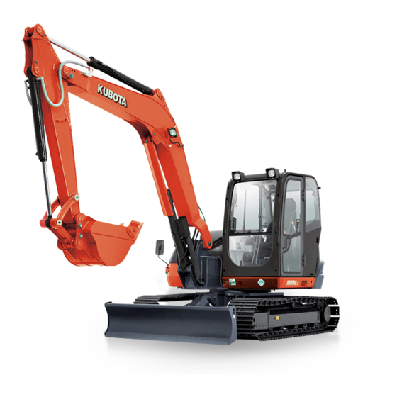
- Page 1 OPERATOR'S MANUAL MODEL 080-3 English (Australia) Code No. RD819-8131-7 1BAAABSAP0010 READ AND SAVE THIS MANUAL PRINTED IN JAPAN © KUBOTA Corporation 2007...
- Page 2 Operator Protective Guards of Top Guard Level I Guard Level I) Revolutions Per Minute ROPS Roll-Over Protective Structures Society of Automotive Engineers, USA TPSS Two Pattern Selection System Auto Idle KX080-3 AR . K . 6 - 6 . 1 . AK...
- Page 3 GENERAL SYMBOLS The instruments and operation elements have been marked with a series of symbols in order to simplify the operation of excavator. These symbols are listed below with the respective descriptions. Safety alert Symbol Boom swing (left) Warning lamp ''Fuel level too low'' Boom swing (Right) System lamp Dozer raise...
- Page 4 FOREWORD You are now the proud owner of a KUBOTA Excavator. This excavator is a product of KUBOTA quality engineering and manufacturing. It is made of fine materials and under a rigid quality control system. It will give you long, satisfactory service. To obtain the best use of your excavator, please read this manual carefully.
-
Page 5: Table Of Contents
CONTENTS SAFE OPERATION .................... DEALER SERVICE...................... 1 TECHNICAL DATA...................... 2 DESCRIPTION OF MACHINE PARTS................ 3 INSTRUMENT PANEL AND CONTROL ELEMENTS..........4 CHECKS BEFORE START ..................6 DAILY CHECKS....................... 6 Wiper/Washer Switch ....................... 6 Interior Lamp........................7 Beacon Light Switch ......................7 Overload Warning Switch .................... - Page 6 CONTENTS Oil Change in the Run-in Stage ..................22 Seat Belt ......................... 22 STARTING ......................22 Adjusting the Operator's Seat..................23 Lock Lever ........................23 DRIVING ........................ 24 Drive Levers(Right,Left)....................25 Travel Speed Switch....................... 26 TURNS........................27 Pivot Turn ........................27 Spin Turn ........................
- Page 7 CONTENTS Checking Engine Oil Level....................55 Checking Hydraulic Oil Level..................56 Checking V-belt ......................56 Greasing Bucket Pin and Bucket Link Pin ..............57 Checking Radiator and Oil Cooler .................. 57 Checking Washer Liquid....................58 Cleaning Pre-Cleaner ..................... 58 Checking and Cleaning Engine and Electrical Wiring............. 58 Washing Whole Machine ....................
- Page 8 Fuse Capacities and Circuits ..................80 Auxiliary Electric ......................81 Slow Blow Fuse ......................81 TROUBLESHOOTING....................82 KUBOTA I.C.S. NAVIGATION LIST OF MESSAGES ........... 84 OPERATION UNDER COLD WEATHER CONDITIONS .......... 86 PREPARATION FOR OPERATION IN COLD WEATHER ........86 PROCEDURE AFTER DONE WORK..............86 LONG STORAGE ......................
- Page 9 7. Study control lever pattern A and pattern B. Then 3. For your safety, a ROPS/OPG (Top Guard Level I) choose the one which is most familiar. Familiarize with a seat belt is installed by KUBOTA. yourself with the pattern selected by operation slowly A ROPS: Roll-Over Protective Structure A OPG (Top Guard Level I): Operator Protective at low engine speed.
- Page 10 In that case, contact your local KUBOTA dealer. manual has been read and completely understood. 11. Do not wear baggy, torn or oversized clothing when working with the excavator.
- Page 11 SAFE OPERATION 8. Precautions against tipping over. Keep away from STARTING OF THE EXCAVATOR steep slopes and embankments. Do not swing the bucket downhill. Lower the dozer during digging. Keep the bucket as low as possible while driving uphill. Turn 1.
- Page 12 SAFE OPERATION SAFE LOADING AND TRANSPORT OF AFTER OPERATION THE EXCAVATOR Before leaving the machine, 1. Observe all regulations concerning the transport of A Park the excavator on a firm, flat and level surface. excavators on public roads. A Lower the attachments and the dozer blade to the 2.
- Page 13 SAFE OPERATION 9. Leaking hydraulic fluid has enough pressure to Max. drawbar pull at 116.9 kN (26280 lbf, 11920 kgf) penetrate the skin and cause serious injuries. coupling hook Leakages from pin holes can be totally invisible. Do Max. vertical load at not use hands for checking for leaks.
- Page 14 Keep the lock lever for attachment control in the "LOCK" position. 17. KUBOTA uses no parts which are lined with asbestos. Do not use these kind of parts even if they are available and can be installed.
- Page 15 SAFE OPERATION...
- Page 16 SAFE OPERATION...
- Page 17 SAFE OPERATION...
- Page 18 SAFE OPERATION...
- Page 19 SAFE OPERATION...
- Page 20 SAFE OPERATION...
- Page 21 2. Clean danger, warning and caution labels with soap and water, dry with a soft cloth. 3. Replace damaged or missing danger, warning and caution labels with new labels from your KUBOTA dealer. 4. If a component with danger, warning and caution label(s) affixed is replaced with new part, make sure new label(s) is (are) attached in the same location(s) as the replaced component.
-
Page 23: Safe Operation
DEALER SERVICE DEALER SERVICE Your KUBOTA dealer is always ready to help so that your excavator offers the best performance. After having carefully read these instructions, you will realize that much of the routine maintenance can be done by yourself. -
Page 24: Technical Data
(kgf/ (210) Fuel tank capacity A Above dimensions are based on the machine with KUBOTA original bucket and 2100 arm. A Specifications subject to change without notice. D With unloaded digging bucket. D Firm compacted soil. D Operators must exercise extra caution and follow instructions in the operator's manual. -
Page 25: Description Of Machine Parts
DESCRIPTION OF MACHINE PARTS DESCRIPTION OF MACHINE PARTS DEPICTED CONTENTS (1) Arm (2) Bucket cylinder (3) Bucket link 2 and 3 (4) Bucket link 1 (5) Bucket (6) Boom cylinder (7) Dozer cylinder (8) Dozer blade (9) Arm cylinder (10) Boom (11) Working light (12) Cabin (13) Operator's seat... -
Page 26: Instrument Panel And Control Elements
INSTRUMENT PANEL AND CONTROL ELEMENTS INSTRUMENT PANEL AND CONTROL ELEMENTS B Instrument Panel, Switch DEPICTED CONTENTS (1) Second service port switch (10) Switch for Auto idle control (2) First service port switch (11) Wiper / Washer switch (3) Horn switch (12) Cab light switch (4) One way hold lock switch (13) Overload warning switch... - Page 27 INSTRUMENT PANEL AND CONTROL ELEMENTS B Control Pedals and Levers DEPICTED CONTENTS (1) Drive lever (left) (2) Lock lever* (3) Control lever for front attachments (left) (4) Drive pedal (5) Drive lever (right) (6) Control lever for front attachments (right) (7) Dozer control lever (8) Throttle potentiometer (9) Boom swing pedal...
-
Page 28: Checks Before Start
CHECKS BEFORE START CHECKS BEFORE START DAILY CHECKS BWiper/Washer Switch In order to avoid damage, it is important to check the To move the wiper, turn on the switch for the wiper when condition of the excavator before starting. the starter key in position "RUN"( ). -
Page 29: Interior Lamp
CHECKS BEFORE START BInterior Lamp BOverload Warning Switch To turn on the interior lamp, set the interior lamp switch to the "ON" positions. To avoid personal injury or death: A Continuing to apply the load after the overload warning horn sounds could result in the machine tipping over. -
Page 30: Working Light Switch
CHECKS BEFORE START BWorking Light Switch BOpening/Closing of CAB Door When the starter switch is in position "RUN", the light(s) 1. Unlock the CAB door and pull the knob. Open the CAB door fully until fixed into place. will be switched on by pressing the switch. 2. -
Page 31: Opening/Closing Of Front Cab Window
CHECKS BEFORE START BOpening/Closing of Front CAB Window BOpening/Closing of Side CAB Window 1. Pull the grip to release the lock and pull side window open to the rear or to the front. 2. To close the side window, slide it forward or backward To avoid personal injury: until the lock snaps in at the window frame. -
Page 32: Air Conditioner
CHECKS BEFORE START AIR CONDITIONER Position the inlet selector lever to the desired position. BAir Flow Air in the CAB and fresh air introduced into the CAB flow as shown in the figure. Adjust the five air outlet ports to obtain the desired condition. -
Page 33: Air Control Vent
CHECKS BEFORE START BAir Control Vent BControl Panel C Front air outlet The front air outlets can be independently adjusted as required. To defrost the windshield, rotate the outlets toward the windshield. (1) Air conditioner switch with indicator light (2) Temperature control lever (3) Blower switch C Air Conditioner Switch with Indicator Light (1) Front air outlet... -
Page 34: Operation
CHECKS BEFORE START HANDLING THE SAFETY DEVICES BOperation BControl Lever Lock C Heating 1. Adjust the blower (1/2/3) switch and the temperature control lever to achieve the desired temperature level. A When the excavator is not used or left unattended, be sure to place the lock lever in position "Lock". -
Page 35: Operation Of The Engine
OPERATION OF THE ENGINE OPERATION OF THE ENGINE A When the engine gets started, the meter may momentarily turn off and a peep may sound. This is not a trouble. The symbol may also appear for a short To avoid personal injury: time. - Page 36 OPERATION OF THE ENGINE 2. Pull the lock lever all the way back. (lock position) 3. Put the throttle potentiometer in the middle between " " and " " symbols. The switch for Auto Idle control is in the OFF position. (See "AUTO IDLE (AI) OPERATION"...
-
Page 37: Display Selector Switch
OPERATION OF THE ENGINE BCharge Lamp BDisplay Selector Switch This warning lamp lights up if the charging system fails the engine running. When the starter switch is turned "RUN" Press the display selector switch while the engine is with the engine off, the lamp lights up, and when the running. -
Page 38: Lcd Display For Normal Operation
OPERATION OF THE ENGINE BLCD Display for Normal Operation C Fuel gauge To avoid personal injury: 2. The message shown above appears. A Before adding fuel, be sure to stop the engine. 3. Add fuel. A Be sure to keep open flame away from the 4. -
Page 39: Lcd Display For Warning
OPERATION OF THE ENGINE C Hour-meter BLCD Display for Warning Indicates the total operating hours of the machine. C Remaining fuel warning How the indicator works When the fuel level is very low, the lamp (yellow) starts A The meter advances one hour after an hour of flashing and the following message appears in the operation regardless of the engine rpm. -
Page 40: Warning Lamp
A Stop the engine and remove the key before buzzer beeps. fuelling. A Let your KUBOTA dealer inform you of details A Do not smoke while fuelling. concerning care and maintenance. This device automatically supplies fuel to the fuel tank and stops automatically when the fuel tank is full. -
Page 41: Checkpoints After Starting The Engine
A Sudden abnormal noises are heard. A Exhaust is black. A Warning lamp for engine oil lights up during operation. A In these cases, the excavator must be checked and serviced by your local the KUBOTA dealer. (3) Switch (black button) (4) Switch (red button) -
Page 42: Starting The Engine Under Cold Conditions
OPERATION OF THE ENGINE STARTING THE ENGINE UNDER COLD STOPPING THE ENGINE CONDITIONS To avoid personal injury or death: A Do not keep the bucket or dozer in the lifted To avoid personal injury: position, as a person could accidentally touch A Make sure that the lock lever is in the lock the levers and cause serious accidents. -
Page 43: Starting With An Auxiliary Battery
OPERATION OF THE ENGINE STARTING WITH AN AUXILIARY BATTERY To avoid personal injury: A Battery gases can explode. Do not smoke and keep sparks and flames away. A Do not start the engine with an auxiliary battery if excavator battery is frozen. A Do not connect the black jumper cable to the negative (-) terminal of the excavator battery. -
Page 44: Excavator Operation
EXCAVATOR OPERATION EXCAVATOR OPERATION RUNNING-IN OF THE NEW EXCAVATOR BSeat Belt The operation and care of the new excavator influences its life span. Your new excavator has been carefully checked and tested before leaving the factory. In spite of this, all movable components must run-in during the first To avoid personal injury or death: 50 work hours. -
Page 45: Adjusting The Operator's Seat
EXCAVATOR OPERATION C Arm rest angle adjustment Turn the arm rest angle adjust knob to the desired BAdjusting the Operator's Seat angle. BLock Lever To avoid personal injury: A Make sure that the seat is completely secured after each adjustment. To avoid personal injury: A To avoid injuries, check safety aspects all around the excavator. -
Page 46: Driving
EXCAVATOR OPERATION DRIVING A Recommended technique for working on a slope. To avoid personal injury or death: A Before starting the engine, make sure that no one is near the excavator. A Before operating the excavator, check the track direction. (Front idler and dozer blade to the front of the excavator). -
Page 47: Drive Levers(Right,Left)
EXCAVATOR OPERATION 3. Activate the dozer control lever to raise the dozer. BDrive Levers(Right,Left) To avoid personal injury or death: A If the swing frame has been turn 180 deg, i.e. the dozer in relation to the operator's seat is "behind", then the travel direction is opposite to the drive direction of the levers (when activating the drive lever forward, the machine, in relation... -
Page 48: Travel Speed Switch
EXCAVATOR OPERATION A It automatically changes into first speed (low speed) BTravel Speed Switch when the drive resistance grows while traveling Travel speed will increase when this switch is pushed second speed (high speed). down. Thereafter, when the resistance lightens, it returns to Switching the dual travel speed: second speed. -
Page 49: Turns
EXCAVATOR OPERATION TURNS 2. While travelling backward, bring the left drive lever into the neutral position; the excavator will turn in the direction of the arrow of the illustration below. To avoid personal injury: A Do not change direction on steep slopes, or the excavator could tip over. -
Page 50: Spin Turn
While traveling uphill, keep the lower edge of the bucket approx. 20 to 40 cm above the ground. Although the KUBOTA excavator will not slip easily because of the tracks, it is safer to let the bucket slide over the ground while traveling downhill. -
Page 51: Parking On A Slope
EXCAVATOR OPERATION PARKING ON A SLOPE OPERATION OF THE DOZER 1. To raise the dozer, pull back the control lever. To lower the dozer, push the control lever forward. To avoid personal injury or death: A When excavator parked left unattended on a slope, be sure to put the bucket on the ground and place all control levers in neutral position, then brace the tracks... -
Page 52: Two Pattern Selection System(Tpss)
EXCAVATOR OPERATION TWO PATTERN SELECTION SYSTEM(TPSS) To avoid personal injury: A Study control lever pattern A and pattern B. Then choose the one which is most familiar. A Position the pattern selector lever (located on the left side of operator's seat) in either the rear position (pattern A) or the front position (pattern B). -
Page 53: Operation Of The Boom
EXCAVATOR OPERATION OPERATION OF THE BOOM OPERATION OF THE ARM To raise the boom, pull the attachment control lever back. Pull back the attachment control lever and the arm will be The boom is equipped with a cushion cylinder which helps pulled in. -
Page 54: Operation Of The Bucket
EXCAVATOR OPERATION OPERATION OF THE BUCKET UNIT SWING AND BOOM SWING OPERATION To dig using the bucket, move the right attachment control lever from the neutral position, left. Moving the control lever right, moves the bucket outwards and empties its contents. -
Page 55: Boom Swing Operation
EXCAVATOR OPERATION BBoom Swing Operation 1. Flip the pedal lock up to unlock the pedal. 2. Step on the left side of the pedal to swing the boom to the left. 3. Step on the right side of the pedal to swing the boom to the right. -
Page 56: Service Port Operation
EXCAVATOR OPERATION SERVICE PORT OPERATION A When the lock lever is raised, the service port activation switch is off. A Let the engine warm up after start-up for approx. 10 minutes under no load conditions. BFirst Service Port Operation The service port switch is used to operate hydraulic attachment such as hammers. - Page 57 EXCAVATOR OPERATION C Usual settings A Action mode of the first service port operation It is possible to select from four action modes of the first service port operation by pushing the service port activation switch. Each time the service port activation switch is pushed, the action mode changes from 1 through 4. A When turning the starter key to the "RUN"...
- Page 58 EXCAVATOR OPERATION A Setting of limited flow volume Max. flow volume right and left can be adjusted in 15 stages independently.
- Page 59 EXCAVATOR OPERATION A Service Port Max. Flow Volume Max. Flow Volume (Theoretical L/min.) Max. pressure 20.6 (210) MPa (kgf/cm )
-
Page 60: One Way Flow Operation (First Service Port)
EXCAVATOR OPERATION A When the service port is not used for a long period, dirt particles can settle in the lower part of the service port lines. When the plugs on the service port lines are removed to connect attachments, drain approx. 100 cc (3.4 oz) of oil per side before making connections. -
Page 61: Second Service Port Operation
EXCAVATOR OPERATION BSecond Service Port Operation C Service Port Max. Flow Volume Max. Flow Volume (Theoretical L/min.) Max. pressure 20.6 (210) MPa (kgf/cm ) A When the service port is not used for a long period, dirt particles can settle in the lower part of the service port lines. When the plugs on the service port lines are removed to connect attachments, drain approx. -
Page 62: 1-Way Or 2-Way Circuit Selection Valve Operation
EXCAVATOR OPERATION 1-way or 2-way CIRCUIT SELECTION VALVE OPERATION A selection valve which selects 1-way or 2-way circuit of service port has been installed on the hydraulic tank. 1. When equipment which needs a 1-way circuit will be used, position the arrow, by using the selector lever, on the axis of the selection valve to the 1-way circuit position, to reduce the back pressure. -
Page 63: Emergency Shut-Off Valve
Do not move the operating lever to the boom lowering 45-degree turn at a time. Be careful not to side. Contact a KUBOTA dealer for maintenance. loosen it a full turn or more at once because otherwise oil may squirt out accidentally. -
Page 64: Auto Idle (Ai) Operation
EXCAVATOR OPERATION AUTO IDLE (AI) OPERATION IMPORTANT INFORMATION ON EXCAVATOR OPERATION 1. Throttle Potentiometer With this potentiometer the operator can adjust the A Do not try to crush concrete or boulders using side engine speed when the Auto Idle control is activated. swings with the bucket. -
Page 65: How To Release Pressure Trapped In The Hydraulic System
EXCAVATOR OPERATION HOW TO RELEASE PRESSURE TRAPPED IN THE HYDRAULIC SYSTEM A Lower the attachments and the dozer blade to the ground. A Turn the key to "STOP" position and shut off the engine. A After stopping the engine, turn the key to "RUN" position. -
Page 66: Transporting The Excavator On A Vehicle
TRANSPORTING THE EXCAVATOR ON A VEHICLE TRANSPORTING THE EXCAVATOR ON A VEHICLE B Transporting on a truck To avoid serious injury or death: A No directional changes should be made when To avoid personal injury or death: the excavator is on the ramp. Should a change A After loading the machine on the truck, lower of direction be necessary, drive off the ramp the bucket and dozer onto the truck bed. - Page 67 TRANSPORTING THE EXCAVATOR ON A VEHICLE 3. For additional safety, use blocks or supports under the ramps and the bed. (1) Cable or strap (2) Block 4. Completely align the ramps and the tracks and then drive the excavator slowly up the ramps. After B Towing the machine ensuring that the tracks are completely on the bed, swing the upper body around to the back of the...
-
Page 68: Lifting Of The Excavator
LIFTING OF THE EXCAVATOR LIFTING OF THE EXCAVATOR B Lifting Procedure for the Excavator To avoid serious injury or death: A The correct instructions for safe handling are To avoid personal injury or death: described here. Read these instructions A Do not use the hooks on the roof of canopy and carefully before moving the machine. - Page 69 LIFTING OF THE EXCAVATOR 3. Tackle The weights of the excavators and the recommended tackle for lifting these loads are mentioned in the following table. Choose components having enough strength. Excavator Weight* 8250 30.7 Load / Cable (kgf) (3131) Minimum Wire Diameter 22.4 or more (Safety factor=6) *Excavator Weight: With CAB, steel tracks.
-
Page 70: Maintenance
MAINTENANCE MAINTENANCE MAINTENANCE INTERVALS Hour meter indicator Ref. Check points Measures Interval page check Daily check Coolant change every 2 years Fuel check Daily check check Daily check Engine oil change every 250 hrs check Daily check Hydraulic oil change every 1000 hrs Bucket and bucket Daily check... - Page 71 MAINTENANCE Hour meter indicator Ref. Check points Measures Interval page 1000 check Daily check Coolant change every 2 years Fuel check Daily check check Daily check Engine oil change every 250 hrs check Daily check Hydraulic oil change every 1000 hrs Bucket and bucket link pin / Dozer Daily check...
- Page 72 *4 Consult your local KUBOTA Dealer for this service. A The items listed above (@ marked) are registered as emission related critical parts by KUBOTA in the U.S.EPA non-road emission regulation. As the engine owner, you are responsible for the performance of the required...
-
Page 73: Opening And Closing Of Parts
MAINTENANCE OPENING AND CLOSING OF PARTS BOpening/Closing of the Engine Hood BOpening/Closing of the Fuel Tank Cover Insert the key into the key slot and turn it clockwise to unlock it. Then press the button to open the tank cover. To avoid personal injury: To close it, lower the tank cover and push it tightly. -
Page 74: Opening/Closing Of The Side Cover
MAINTENANCE BOpening/Closing of the Side Cover BWhere to store the Tool 1. Open the engine hood. 1. Open the side cover. 2. Raise the catch lever to unlock the side cover. 2. Store the tools in the storage box. 3. Push the side cover all the way forward, and it will be held by a link. -
Page 75: Where To Keep Operator's Manual
MAINTENANCE BWhere to keep Operator's Manual BCup Holder (1) Operator's manual storage (1) Cup holder BUtility Box BWhere to Store the Fire Extinguisher 1. Open the rear cover. (1) Fire extinguisher (1) Utility box... -
Page 76: Daily Checks
MAINTENANCE DAILY CHECKS A Do not fill the recovery tank over the "FULL" marking. A Do not fill with dirty or salty water. To avoid personal injury: BChecking Fuel Level A Do not operate the excavator while putting out the hands and the body from the windows. A Do not touch the control levers and the pedals from outside the cab during the engine To avoid personal injury:... -
Page 77: Checking Engine Oil Level
MAINTENANCE 3. If necessary, open the tank cover with the starter key, open the cap and fill in fuel. BChecking Engine Oil Level A See "Opening and Closing of the Fuel Tank Cover" and see Fuel supply in the "LCD Display for Usual Operation"... -
Page 78: Checking Hydraulic Oil Level
MAINTENANCE BChecking Hydraulic Oil Level To avoid personal injury: A Stop the engine and remove the key before checking the oil level. A Before filling oil, wipe away all sand and dust from around the oil port. Make sure to use an identical type of hydraulic fluid. -
Page 79: Greasing Bucket Pin And Bucket Link Pin
MAINTENANCE BGreasing Bucket Pin and Bucket Link Pin BChecking Radiator and Oil Cooler To avoid personal injury: To avoid personal injury: A First lower all attachments on the ground then A Always stop the engine and remove the key stop the engine and remove the key. before checking the radiator. -
Page 80: Checking Washer Liquid
MAINTENANCE BCleaning Pre-Cleaner To clean the pre-cleaner, remove the wing nut and remove the pre-cleaner bowl. (1) Rubber hoses and clamps A Radiator and oil cooler fins and ribs must be clean in order not to overheat the engine and allow free flow of (1) Wing nut (A) "DUST LEVEL"... -
Page 81: Regular Checks And Maintenance Work
REGULAR CHECKS AND MAINTENANCE WORK REGULAR CHECKS AND MAINTENANCE WORK BDraining Water Separator 1. Open the side cover. To avoid personal injury: 2. When the separated water is entering the sediment A Do not operate the excavator while putting out the hands and the body from the windows. -
Page 82: Battery
REGULAR CHECKS AND MAINTENANCE WORK BBattery To avoid the possibility of a battery explosion: For refillable type battery, follow the instructions below. A Do not use or charge the refillable type battery if the fluid level is below the LOWER (lower limit level) mark. -
Page 83: Battery Charging
REGULAR CHECKS AND MAINTENANCE WORK BBattery Charging BGreasing Swing Bearing Teeth 1. Pump grease with the grease gun through the grease nipple. 2. Grease at each 90 (1.58 rad.) position of the swing To avoid personal injury: frame. A When the battery is being activated, hydrogen 3. -
Page 84: Every 200 Service Hours
REGULAR CHECKS AND MAINTENANCE WORK EVERY 200 SERVICE HOURS C Checking and adjustment of the alternator belt tension Do all 50 and 100 hour servicing at the same time. 1. Press the alternator belt down in the middle, with a force of approx. -
Page 85: Checking Radiator Hoses And Clamps
REGULAR CHECKS AND MAINTENANCE WORK C Checking and adjustment of the fan belt tension 1. Press the fan belt down in the middle, with a force of approx. 10 kg. The belt tension is correct if it deflects about 20 mm. If otherwise, loosen bolt (1) and (2) and shift the air-compressor (3) in the direction shown by the arrow. -
Page 86: Air Filter Maintenance
REGULAR CHECKS AND MAINTENANCE WORK BAir Filter Maintenance BGreasing Swing Ball Bearing 1. Grease through the respective grease nipple. (at the central nipple) 2. Grease at each 90 (1.58 rad.) position of the swing To avoid personal injury: frame. A Wear eye protection. 3. -
Page 87: Checking Fuel Line And Intake Air Line
REGULAR CHECKS AND MAINTENANCE WORK AIR CONDITIONER BChecking Fuel Line and Intake Air Line BCleaning Air Filter 1. Check to see that all lines and hose clamps are Open the cover and remove the filter cover, remove the air tightened and not damaged. filter. -
Page 88: Checking Air-Conditioner Condenser
REGULAR CHECKS AND MAINTENANCE WORK BChecking Air-Conditioner Condenser To avoid personal injury: Check air conditioner condenser to be sure it is clean from A Wear eye protection. debris. (1) Air conditioner condenser C Cleaning the air filter A Normal use Blow air from the opposite direction to the filter's normal air flow. -
Page 89: Every 250 Service Hours
REGULAR CHECKS AND MAINTENANCE WORK EVERY 250 SERVICE HOURS Do all 50 hour servicing at the same time. BEngine Oil Change (First Engine Oil Change after 50 Service Hours) To avoid personal injury: A First stop the engine then remove the key and wait long enough for the oil to cool down. -
Page 90: Replacing Engine Oil Filter
REGULAR CHECKS AND MAINTENANCE WORK BReplacing Engine Oil Filter BGreasing Front Attachments (without Bucket Pin and Boom Swing Fulcrum) 1. Replace the oil filter cartridge at the same time as doing the engine oil change. 2. Remove the cartridge with the supplied filter wrench. To avoid personal injury: A First lower all attachments on the ground then stop the engine and remove the key. -
Page 91: Every 500 Service Hours
REGULAR CHECKS AND MAINTENANCE WORK EVERY 500 SERVICE HOURS Do all 50, 100 and 250 hour servicing at the same time. BDrive Unit Oil Change(First Oil Change of the 100 hours) To avoid personal injury: A Lower all attachments to the ground, stop the engine and remove the key before undertaking the oil change. -
Page 92: Replacing Fuel Filter Cartridge
REGULAR CHECKS AND MAINTENANCE WORK BReplacing Fuel Filter Cartridge To avoid personal injury: A Keep fire away. 1. Remove the filter with the filter wrench. 2. Apply a light film of fuel to the seal of the new filter and turn in tightly by hand. -
Page 93: Every 1000 Service Hours
REGULAR CHECKS AND MAINTENANCE WORK EVERY 1000 SERVICE HOURS Do all 50, 100, 200, 250 and 500 hour servicing at the same time. BReplacing the Hydraulic Pilot Filter Element To avoid personal injury: A Before replacing the element, wait long enough for the hydraulic fluid to cool down. -
Page 94: Hydraulic Oil Change (Including Replacing Of The Suction Filter In The Hydraulic Tank)
REGULAR CHECKS AND MAINTENANCE WORK BHydraulic Oil Change (Including Replacing of the Suction Filter in the Hydraulic Tank) To avoid personal injury: A Wait long enough for the hydraulic fluid to cool down. Then begin with the change of the hydraulic fluid. -
Page 95: Hydraulic Oil Check With Hydraulic Hammers
REGULAR CHECKS AND MAINTENANCE WORK EVERY 1000 SERVICE HOURS OR ONCE A 9. Fill oil again up to the center of the gauge. YEAR Hydraulic 75 L tank Hydraulic BReplacing Air Filter Element oil volumes Whole oil 146 L Open the engine hood and remove the dust-cover. volumes Remove and replace the outer element and inner element 10. -
Page 96: Every 1500 Service Hours
BIENNIAL SERVICING BChecking Fuel Injection Nozzle(Injection Pressure) To avoid personal injury: Consult your local KUBOTA Dealer for this service. A Do not loosen the radiator cap before the radiator has cooled down sufficiently. Then EVERY 2000 SERVICE HOURS only loosen the cap and allow enough time for the pressure in the system to be released. -
Page 97: Changing Radiator Coolant
REGULAR CHECKS AND MAINTENANCE WORK BChanging Radiator Coolant Stop the engine, then remove the key and wait until it has cooled down completely. 1. Open the drain plug on the bottom of the radiator and drain coolant completely. Should a recovery tank be To avoid personal injury: equipped, disconnect the line from the tank floor and A When using anti-freeze, put on some protection... -
Page 98: Replacing Fuel Hoses And Clamps
REGULAR CHECKS AND MAINTENANCE WORK BReplacing Fuel Hoses and Clamps Replace the hoses and clamps. (See "Checking Fuel and Intake Air Line" in "EVERY 200 SERVICE HOURS") (1) Recovery tank (A) "FULL" (B) "LOW" Radiator 10.5 L Recovery tank 1.3 L (1) Fuel lines (2) Clamp bands A Do not operate the engine without coolant. -
Page 99: Servicing As Required
A Do disconnect part refrigeration circuit of the air conditioning system. Consult your local KUBOTA Dealer for A Charge only with R134a not R12 refrigerant (gas). assistance and service. A shortage of refrigerant impairs the air-conditioner performance. Check the following points. If it is indicated that the amount of refrigerant is extremely low, ask your dealer to inspect and charge. -
Page 100: Other Adjustments And Replacements
OTHER ADJUSTMENTS AND REPLACEMENTS OTHER ADJUSTMENTS AND REPLACEMENTS PURGING OF THE FUEL SYSTEM After adjustment is completed: Using the socket wrench, tighten the grease nipple. 1. Fill up the excavator with fuel. Tightening torque must be between 98 to 108 N-m. 2. -
Page 101: Special Information When Using Rubber Tracks
OTHER ADJUSTMENTS AND REPLACEMENTS To avoid serious injury or death: A Do not work under the machine in this condition. A For your safety do not rely on hydraulically supported devices, they may leak down and suddenly drop or be accidentally lowered. To avoid personal injury or death: A When lifting the machine itself with an attachment, place a safety block or safety post... -
Page 102: Changing The Bucket
(G) 15A Wiper / Washer (Q) 10A Meter Main attachments are installed instead of Kubota specified bucket. (H) 5A Anti-theft Main (R) 5A Travel Hi-Low FUSES 10A Overload Warning (S) 5A Relay Source (J) 10A Starter... -
Page 103: Auxiliary Electric
Max power is less than 110 W including the "Beacon". 2. Remove the slow blow fuse case. If you need another auxiliary electric, contact your KUBOTA dealer for details. (1) Slow blow fuse case 3. Open the slow blow fuse case cap and cover then (1) Auxiliary electric remove the bolts and draw out the slow blow fuse (A). -
Page 104: Troubleshooting
TROUBLESHOOTING TROUBLESHOOTING If the excavator does not show the desired performance, or when trouble arises, refer to the table below and undertake appropriate measures. Trouble Cause Countermeasure Lock levers in "UNLOCK" * Bring lock lever into "LOCK" position. position * Check fuel tank and filter. Fuel is too viscous. - Page 105 TROUBLESHOOTING Trouble Cause Countermeasure Cylinder head gasket is * Replace. damaged (Coolant loss). Water Engine oil level too low * Fill to prescribed level. temperature Engine in red zone Maladjustment of fuel * Readjust ignition timing. (Overheating) injection Use of poor fuel * Use prescribed fuel.
-
Page 106: Kubota I.c.s. Navigation List Of Messages
TROUBLESHOOTING KUBOTA I.C.S. NAVIGATION LIST OF MESSAGES If an error occurs with the machine, one of the following messages appears in the LCD display. In case of a trouble, immediately contact your local dealer for inspection and repair. Warning Problem or failure... - Page 107 A When the display selector switch of the panel is pushed for more than 3 seconds, the message disappears. C In case the service hour meter replaced due to any trouble with it, the meter is set to "0". Contact your KUBOTA dealer...
-
Page 108: Operation Under Cold Weather Conditions
OPERATION UNDER COLD WEATHER CONDITIONS OPERATION UNDER COLD WEATHER CONDITIONS PREPARATION FOR OPERATION IN COLD PROCEDURE AFTER DONE WORK WEATHER Clean the excavator thoroughly after work and wipe dry. Otherwise mud and earth on the tracks could freeze if the 1. -
Page 109: Long Storage
LONG STORAGE LONG STORAGE To avoid personal injury: A Do not clean the excavator with the engine running. A To avoid the danger of exhaust fume poisoning, do not operate the engine in a closed building without proper ventilation. A When storing, remove the key from the starter switch to avoid unauthorized persons from operating the excavator and getting injured. - Page 110 Control valve - Pipe, Boom Hydraulic hose (Service port) Pipe, Boom - Pipe, Boom Pipe, Boom - Pipe, Arm Hydraulic hose (Swivel motor) Control valve - Swivel motor To prevent serious damage to the hydraulic system, use only a KUBOTA genuine hydraulic hose.
-
Page 111: Recommended Oils
RECOMMENDED OILS RECOMMENDED OILS 1. Before delivery the hydraulic oil used was Shell Tellus S2M46. 2. Use engine oil API service classification CF or CI-4. 3. Use SAE 90 (API, GL-4/GL-5) as drive unit oil for all seasons. - Page 112 A Refer to the following table for the suitable API classification engine oil according to the engine type (with internal EGR, external EGR or non-EGR) and the fuel. except external EGR with external EGR Model KX080-3 Engine oil classification (API classification) Fuel used Oil class of engines except external EGR Oil class of engines with external EGR...
-
Page 113: Appendices
4990 7330 KX080-3 2540 2200 7170 1460 6450 2150 2490 A Above dimensions are based on the machine with KUBOTA original bucket. A Above dimensions are based on the machine with rubber track. A Specifications subject to change without notice. -
Page 114: Lifting Capacity
LIFTING CAPACITY LIFTING CAPACITY 1. The lifting capacities are based on ISO 10567 and do not exceed 75% of the static tilt load of the machine or 87% of the hydraulic lifting capacity of the machine. 2. The strokes are as follows. (1) The load point corresponds to the front bolt part of the arm. - Page 115 LIFTING CAPACITY...
Need help?
Do you have a question about the KX080-3 and is the answer not in the manual?
Questions and answers