Table of Contents
Advertisement
Quick Links
U.S.A.
: KUBOTA TRACTOR CORPORATION
3401 Del Amo Blvd., Torrance, CA 90503, U.S.A.
Telephone : (310)370-3370
Western Division
: 1175 S. Guild Avc., Lodi, CA 95240
Telephone : (209)334-9910
Central Division
: 14855 FAA Blvd., Fort Worth, TX 76155
Telephone : (817)571-0900
Northern Division
: 6300 at One Kubota Way, Groveport, OH 43125
Telephone : (614)835-1100
Southeast Division : 1025 Northbrook Parkway, Suwanee, GA 30024
Telephone : (770)995-8855
Canada
: KUBOTA CANADA LTD.
5900 14th Avenue, Markham, Ontario, L3S 4K4, Canada
Telephone : (905)294-7477
France
: KUBOTA EUROPE S.A.S
19-25, Rue Jules Vercruysse, Z.I. BP88, 95101 Ar enteuil Cedex, France
Telephone : (33)1-3426-3434
Italy
: KUBOTA EUROPE S.A.S Italy Branch
Via Grandi, 29 20068 Peschiera Borrome (MI) Italy
Telephone : (39)02-51650377
Germany
: KUBOTA BAUMASCHINEN GmbH
Steinhauser str, 100, 66482 Zweibrucken Rheinlandpfalz Germany
Telephone : (49)6332-4870100
U.K.
: KUBOTA (U.K.) LTD.
Dormer Road, Thame, Oxfordshire, OX9 3UN, U.K.
Telephone : (44)1844-214500
Australia
: KUBOTA TRACTOR AUSTRALIA PTY LTD.
25-29 Permas Way, Tru anina, VIC 3029, Australia
Telephone : (61)-3-9394-4400
Malaysia
: SIME KUBOTA SDN. BHD.
No.3 Jalan Sepadu 25/123 Taman Perindustrian Axis,
Seksyen 25, 40400 Shah Alam, Selan or Darul Ehsan Malaysia
Telephone : (60)3-736-1388
Philippines : KUBOTA PHILIPPINES, INC.
232 Quirino Hi hway, Baesa, Quezon City 1106, Philippines
Telephone : (63)2-422-3500
Taiwan
: SHIN TAIWAN AGRICULTURAL MACHINERY CO., LTD.
16, Fen pin 2nd Rd, Taliao Shian Kaohsiun 83107, Taiwan R.O.C.
Telephone : (886)7-702-2333
Thailand
: SIAM KUBOTA CORPORATION CO., LTD.
101/19-24 Moo 20, Navanakorn Industrial Estate, Tambon Khlon nuen , Amphur Khlon luan ,
Pathumthani 12120, THAILAND
Telephone : (66)2-909-0300
Japan
: KUBOTA Corporation
Farm & Industrial Machinery International Operations Headquarters
2-47, Shikitsuhi ashi 1-chome, Naniwa-ku, Osaka, Japan 556-8601
Advertisement
Table of Contents

Related Manuals for Kubota KX080-4


Summary of Contents for Kubota KX080-4
- Page 1 Telephone : (49)6332-4870100 U.K. : KUBOTA (U.K.) LTD. Dormer Road, Thame, Oxfordshire, OX9 3UN, U.K. Telephone : (44)1844-214500 Australia : KUBOTA TRACTOR AUSTRALIA PTY LTD. 25-29 Permas Way, Tru anina, VIC 3029, Australia Telephone : (61)-3-9394-4400 Malaysia : SIME KUBOTA SDN. BHD. No.3 Jalan Sepadu 25/123 Taman Perindustrian Axis, Seksyen 25, 40400 Shah Alam, Selan or Darul Ehsan Malaysia Telephone : (60)3-736-1388 Philippines : KUBOTA PHILIPPINES, INC. 232 Quirino Hi hway, Baesa, Quezon City 1106, Philippines Telephone : (63)2-422-3500 Taiwan : SHIN TAIWAN AGRICULTURAL MACHINERY CO., LTD. 16, Fen pin 2nd Rd, Taliao Shian Kaohsiun 83107, Taiwan R.O.C. Telephone : (886)7-702-2333 Thailand : SIAM KUBOTA CORPORATION CO., LTD. 101/19-24 Moo 20, Navanakorn Industrial Estate, Tambon Khlon nuen , Amphur Khlon luan , Pathumthani 12120, THAILAND Telephone : (66)2-909-0300 Japan : KUBOTA Corporation Farm & Industrial Machinery International Operations Headquarters...
- Page 2 ABBREVIATION LIST of Germany d dozer California Proposition 65 WARNING Engine exhaust, some of its constituents, certain vehicle components and fluids, contain or emit chemicals known to the X080-4 State of California to cause cancer and birth English (U.S.A.) defects or other reproductive harm. AU.
- Page 3 GENERAL SYMBOLS The instruments and operation elements have been marked with a series of symbols in order to simplify the operation of excavator. These symbols are listed below with the respective descriptions. Safety alert Symbol Boom swing (left) Warning lamp ''Fuel level too low'' Boom swing (Right) System lamp Dozer raise...
- Page 4 FOREWORD SAFETY FIRST This symbol, the industry's "Safety Alert Symbol", is used throughout this manual and on labels on the machine itself to warn of the possibility of personal injury. Read these instructions carefully. It is essential that you read the instructions and safety regulations before you attempt to assemble or use this unit.
-
Page 5: Table Of Contents
CONTENTS SAFE OPERATION ..................... -1 DEALER SERVICE...................... 1 TECHNICAL DATA...................... 2 DESCRIPTION OF MACHINE PARTS................ 3 INSTRUMENT PANEL AND CONTROL ELEMENTS..........4 CHECKS BEFORE START ..................6 DAILY CHECKS....................... 6 CHECKING THE DEVICES ..................6 Starter Switch ........................6 Display Selector Switch ....................7 LCD Display for Normal Operation ................... - Page 6 CONTENTS STARTING THE ENGINE ..................25 STARTING THE ENGINE UNDER COLD CONDITIONS........27 STARTING WITH AN AUXILIARY BATTERY ............27 Observe Following Guidelines when Starting with an Auxiliary Battery......27 CHECK POINTS AFTER STARTING THE ENGINE ..........28 STOPPING THE ENGINE..................29 Engine Stop Button......................
- Page 7 CONTENTS MAINTENANCE......................59 MAINTENANCE INTERVALS ................59 OPENING AND CLOSING OF COVERS............... 64 Opening/Closing of the Fuel Tank Cover................ 64 Opening/Closing of the Engine Hood ................64 Opening/Closing of the Side Cover ................64 Where to store the Tool ....................65 Cup Holder........................
- Page 8 CONTENTS Drive unit Oil Change(First Oil Change of the 50 hours) ..........81 Replacing Fuel Filter Cartridge ..................81 EVERY 1000 SERVICE HOURS ................81 Replacing the Hydraulic Pilot Filter Element..............81 Replacing Hydraulic Return Filter Cartridge ..............82 Hydraulic Oil Change (Including Replacing of the Suction Filter in the Hydraulic Tank) 83 Hydraulic Oil Check with Hydraulic Hammers ..............
- Page 9 CONTENTS Replacing Fuses ......................92 Fuse Capacities and Circuits ..................92 Auxiliary Electric ......................93 Slow Blow Fuse ......................93 Electric Fan Fuse......................93 TROUBLESHOOTING....................94 OPERATION UNDER COLD WEATHER CONDITIONS .......... 96 PREPARATION FOR OPERATION IN COLD WEATHER ........96 PROCEDURE AFTER DONE WORK..............
- Page 11 3. For your safety, a ROPS/OPG (Top Guard Level I) operating the unit slowly and at low engine speed. with a seat belt is installed by KUBOTA. A ROPS: Roll-Over Protective Structure A OPG (Top Guard Level I): Operator Protective...
- Page 12 14. Keep your excavator clean. Heavy soiling, grease, dust and grass can cause fires, accidents or injuries. A Do not allow any persons within the working range of 15. Use only KUBOTA authorized attachments. the excavator during operation. 16. Before starting the excavator, be absolutely sure that...
- Page 13 SAFE OPERATION 5. Do not operate or idle engine in a non-ventilated area. OPERATING THE EXCAVATOR Carbon monoxide gas is colorless, odorless, and deadly. 1. Mount and dismount the machine safely. Always face the machine. Always use handrails and available steps and keep yourself well balanced.
- Page 14 SAFE OPERATION C Safety for children Tragedy can occur if the operator is not alert to the AFTER OPERATION presence of children. Children generally are attracted to machines and the work they do. Before leaving the machine, A Park the excavator on a firm, flat and level surface. If 1.
- Page 15 SAFE OPERATION SAFE LOADING AND TRANSPORT OF Max. drawbar pull at 116.9 kN (26280 lbf, 11920 kgf) THE EXCAVATOR coupling hook Max. vertical load at 12.1 kN (2720 lbf, 1234 kgf) 1. Observe all regulations concerning the transport of coupling hook excavators on public roads.
- Page 16 11. To avoid environmental damage from acid and heavy 18. Inspect ROPS / OPG (Top Guard Level I) for damage metals, dispose of the battery appropriately. and if damage is found contact your KUBOTA dealer 12. Observe all laws and regulations concerning the for repair.
- Page 17 SAFE OPERATION A Examine electrical wiring and connectors frequently 19. KUBOTA does asbestos containing components and recommends against the use of such for damage. Repair any wires that are loose or frayed components. before operating the machine. Clean all electrical...
- Page 18 SAFE OPERATION...
- Page 19 SAFE OPERATION...
- Page 20 SAFE OPERATION...
- Page 21 SAFE OPERATION...
- Page 22 SAFE OPERATION...
- Page 23 SAFE OPERATION...
- Page 24 2. Clean danger, warning and caution labels with soap and water, dry with a soft cloth. 3. Replace damaged or missing danger, warning and caution labels with new labels from your KUBOTA dealer. 4. If a component with danger, warning and caution label(s) affixed is replaced with new part, make sure new label(s) is (are) attached in the same location(s) as the replaced component.
-
Page 25: Safe Operation
DEALER SERVICE DEALER SERVICE Your KUBOTA dealer is always ready to help so that your excavator offers the best performance. After having carefully read these instructions, you will realize that much of the routine maintenance can be done by yourself. -
Page 26: Technical Data
[2987] Fuel tank capacity L(US gal) 115 (30.4) A Above dimensions are based on the machine with KUBOTA original bucket and 2100 arm. A Specifications subject to change without notice. D With unloaded digging bucket. D Firm compacted soil. D Operators must exercise extra caution and follow instructions in the operator's manual. -
Page 27: Description Of Machine Parts
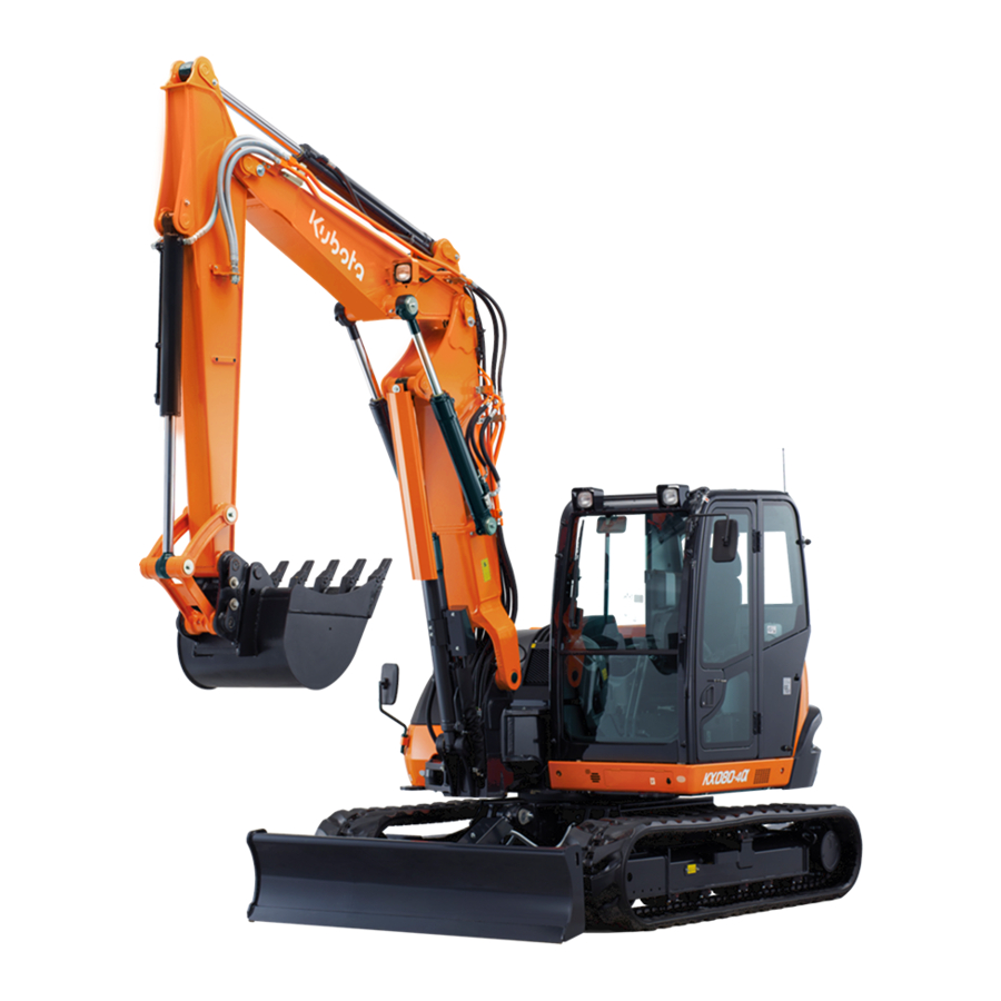
DESCRIPTION OF MACHINE PARTS DESCRIPTION OF MACHINE PARTS DEPICTED CONTENTS (1) Arm (2) Bucket cylinder (3) Bucket link 2 and 3 (4) Bucket link 1 (5) Bucket (6) Boom cylinder (7) Dozer cylinder (8) Dozer blade (9) Arm cylinder (10) Boom (11) Working light (12) Cabin (13) Operator's seat... -
Page 28: Instrument Panel And Control Elements
INSTRUMENT PANEL AND CONTROL ELEMENTS INSTRUMENT PANEL AND CONTROL ELEMENTS B Instrument Panel, Switch (1) LCD display (4) Starter switch (7) Auto idle control switch (9) Eco mode switch (2) Horn switch (5) Throttle potentiometer (8) Angle blade control switch (10) DPF inhibit switch (3) Travel speed switch (6) Light switch... - Page 29 INSTRUMENT PANEL AND CONTROL ELEMENTS B Control Pedals and Levers (1) Drive lever (left) (3) Boom swing pedal (5) Attachment control lever (right) (7) Drive pedal (left) (2) Attachment control lever (left) (4) Drive lever (right) (6) Dozer control lever (8) Drive pedal (right) Ref.
-
Page 30: Checks Before Start
Check the condition of the safety and warning labels. (See "DANGER, WARNING AND CAUTION LABELS" in "SAFE OPERATION" section.) Inspect ROPS / OPG (Top Guard Level I) for damage and if damage is found, contact your KUBOTA dealer for repair. (1) Starter switch (A) STOP... -
Page 31: Display Selector Switch
CHECKS BEFORE START BDisplay Selector Switch BLCD Display for Normal Operation Press the display selector switch while the engine is C Fuel gauge running. The LCD meter display will change from one indication mode to the other. Change the two-mode display according to your jobs. To avoid personal injury: A Before adding fuel, be sure to stop the engine. - Page 32 CHECKS BEFORE START C Overheat warning C Coolant Temperature Gauge 1. If the coolant temperature becomes too high, the message "Water temp. is Rising" appears onscreen for a certain period of time. The LCD display then gets back to normal, but the coolant temperature sensor To avoid personal injury: marker "...
-
Page 33: Warning Lamp
WORK" section) A If any warnings and problems are displayed, an alarm buzzer will beep. (See "LIST OF SCREENS" section for detail.) A See your KUBOTA dealer from details concerning care and maintenance. (1) Engine tachometer C Glow indicator The indicator is displayed when the starter key is turned to the "RUN"... -
Page 34: Lcd Display For Warning
CHECKS BEFORE START C Engine oil pressure low warning BLCD Display for Warning When the engine oil pressure drops too low, the lamp C Remaining fuel warning (red) starts flashing and the following message appears in the display. When the fuel level is very low, the lamp (yellow) starts Immediately stop the engine and check the engine oil flashing and the following message appears in the... -
Page 35: Setting The Clock
CHECKS BEFORE START Information User settings A If you have any question, consult your KUBOTA Dealer. BSetting the Clock 1. Turn the starter key to the "RUN" position. (1) Information switch A " mark" may appear together with a warning message. - Page 36 CHECKS BEFORE START 4. Save the new setting with the switch (Switch 5). 3. Press the switch 2 twice to move the cursor into position. Then press the save switch 5 to make the Press this switch 5 again to set the clock. following screen appear.
-
Page 37: Reordering The Year/Month/Day And Changing The Am/Pm System To The 24-Hour One
CHECKS BEFORE START 3. Press the switch 5 and the following detailed screen shows up. (1) Switch 5 (1) Switch 2 and 3 (A) Year/month/day display BReordering the year/month/day and (2) Switch 4 (B) Clock display (3) Switch 5 Changing the AM/PM System to the 24- hour One (1) Using the switch 2 and 3, move up and down the 1. -
Page 38: Periodic Check
CHECKS BEFORE START 3. Press the switch 2 and 3 to select the log record. Fix this choice with the switch (Switch 5). BPeriodic Check The following message appears on the LCD display 10 hours before a periodic check. Press the switch 4 to see the check results. (1) Switch 1 (4) Switch 2 and 3 (2) Switch 5... -
Page 39: If All The Check Points Are Not Displayed At A Glance On A Single Screen
CHECKS BEFORE START BIf All the Check Points are not Displayed at a Glance on a Single Screen 1. Press the switch 4. 2. Each time the switch 2 or 3 is pressed, the check points scrolled up or down. (1) Switch 4 (3) Switch 3 (2) Switch 2... - Page 40 CHECKS BEFORE START C Service hour meter When the hour meter reaches the hours circled in the maintenance list below, a message appears. The message shows up as follows. Hour meter indicator Check points Measures Intervals 50 100 750 1000 2000 3000 Engine oil (CJ-4) every 500 hrs change...
-
Page 41: When The Check-Up Is Completed
CHECKS BEFORE START BWhen the Check-up is Completed BLight Switch When the check-up is completed, perform the following procedure to make the Periodic Check disappear from the When the starter switch is in position "RUN", the working screen. light(s) and CAB light(s) will be switched on by pressing 1. -
Page 42: Auto Idle Switch
CHECKS BEFORE START BAuto Idle Switch BTravel Speed Switch The switch is used to enable and disable the Auto Idle Travel speed will increase when this switch is pushed control. down. Switching the dual travel speed: A Enable: Press the Auto Idle switch. When the 1. -
Page 43: Inhibit Diesel Particulate Filter (Dpf) Regeneration Switch
CHECKS BEFORE START A The travel speed automatically changes into first BInhibit Diesel Particulate Filter (DPF) speed (low speed) when the drive resistance Regeneration Switch increases while traveling second speed (high speed). Inhibit Diesel Particulate Filter (DPF) regeneration switch Thereafter, when the resistance decreases, it returns (hereinafter called inhibit switch) disables the Auto DPF to second speed. -
Page 44: Eco Mode
CHECKS BEFORE START ECO MODE CAB TYPE MACHINES In the ECO mode, the jobs can be carried on with better BWiper/Washer Switch fuel efficiency than in the standard mode. To engage the wiper, turn on the switch for the wiper when Press the ECO mode switch, and the implement panel the starter key is in the "RUN"... -
Page 45: Heater Switch
CHECKS BEFORE START BHeater Switch BOpening/Closing of CAB Door Turn the starter switch to the "RUN" position and turn the 1. Unlock the CAB door and pull the knob. Open the CAB door fully until fixed into place. heater switch clockwise, the heater fan will be activated 2. -
Page 46: Opening/Closing Of Front Cab Window
CHECKS BEFORE START BOpening/Closing of Front CAB Window BOpening/Closing of Side CAB Window 1. Pull the grip to release the lock and pull side window open to the rear or to the front. 2. To close the side window, slide it forward or backward To avoid personal injury: until the lock snaps in at the window frame. -
Page 47: Air Conditioner
CHECKS BEFORE START AIR CONDITIONER BAir Flow Air in the CAB and fresh air introduced into the CAB flow as shown in the figure. Adjust the five air outlet ports to obtain the desired condition. (C) "FRESH AIR INLET" A Do not allow water to enter the fresh air port while washing the excavator. -
Page 48: Control Panel
CHECKS BEFORE START BControl Panel C Defrosting or demisting To defrost or demist the windshield, take the following steps. 1. Open the front air outlet and direct it to the windshield. 2. Set the blower switch and the temperature control dial "3"... -
Page 49: Operation Of The Engine
OPERATION OF THE ENGINE OPERATION OF THE ENGINE Start the engine in the following manner: 1. Before starting the engine, make sure that all control levers are in the neutral positions. To avoid personal injury: A Read "SAFE OPERATION" at the beginning of this operator's manual. - Page 50 OPERATION OF THE ENGINE 4. Set the starter key to the "RUN" position. Hold the key A If you keep the pilot control lock lever at "UNLOCK" at this position until the " " mark on the display panel and try to start the engine, "Up Lever Lock" appears disappears.
-
Page 51: Starting The Engine Under Cold Conditions
OPERATION OF THE ENGINE STARTING THE ENGINE UNDER COLD STARTING WITH AN AUXILIARY BATTERY CONDITIONS To avoid personal injury: A Battery gases can explode. To avoid personal injury: Do not smoke and keep sparks and flames A Make sure that the lock lever is in the lock away. -
Page 52: Check Points After Starting The Engine
A In these cases, the excavator must be checked and A Using a higher voltage will cause serious damage to serviced by your local the KUBOTA dealer. the electrical system. When using an auxiliary battery, only the compatible (same) voltage is permissible. -
Page 53: Stopping The Engine
OPERATION OF THE ENGINE STOPPING THE ENGINE BPrecautions in case of Overheat To avoid personal injury or death: A Do not keep the bucket or dozer in an elevated To avoid personal injury: A Do not open the radiator cap during operation position, as a person could accidentally touch or just after shut-down. -
Page 54: Excavator Operation
EXCAVATOR OPERATION EXCAVATOR OPERATION RUNNING-IN OF THE NEW EXCAVATOR BAdjusting the Operator's Seat The operation and care of the new excavator influences its life span. Your new excavator has been carefully checked and tested before leaving the factory. In spite of this, all movable components must run-in during the first To avoid personal injury: 50 work hours. -
Page 55: Seat Belt
EXCAVATOR OPERATION STARTING BSeat Belt To avoid personal injury: To avoid personal injury or death: A No persons, other than those who have read A Always use the seat belt with a ROPS/OPG (Top and understand this manual and who are Guard Level I) protection structure. -
Page 56: Driving
EXCAVATOR OPERATION A Recommended technique for working on a DRIVING slope. To avoid personal injury or death: A Before starting the engine, make sure that no one is near the excavator. A Before operating the excavator, check the track direction. (Front idler and dozer blade to the front of the excavator). -
Page 57: Drive Levers(Right,Left)
EXCAVATOR OPERATION TURNS 3. Activate the dozer control lever to raise the dozer. To avoid personal injury: A Do not change direction on steep slopes, or the excavator could tip over. A Before changing direction, beware of people in the work area. BPivot Turn A Movement as illustrated is done with the dozer blade in front of the operator. -
Page 58: Spin Turn
EXCAVATOR OPERATION 2. While travelling backward, bring the left drive lever into 2. Pull the left drive lever backward; the neutral position; the excavator will turn in the direction of the arrow of the excavator will turn in the direction of the arrow of the illustration below. -
Page 59: Up And Downhill Driving
While traveling uphill, keep the lower edge of the bucket approx. 20 to 40 cm (8 to 16 in.) above the ground. Although the KUBOTA excavator will not slip easily because of the tracks, it is safer to let the bucket slide over the ground while traveling downhill. -
Page 60: Two Pattern Selection System(Tpss)
EXCAVATOR OPERATION TWO PATTERN SELECTION SYSTEM(TPSS) To avoid personal injury: A Study control lever pattern A and pattern B. Then choose the one which is most familiar. A Familiarize yourself with the pattern selected by operating slowly. BPattern Change 1. Open the cover and position the pattern selector lever to the desired position. -
Page 61: Operation Of The Boom
EXCAVATOR OPERATION OPERATION OF THE BOOM OPERATION OF THE ARM To raise the boom, pull the attachment control lever back. Pull back the attachment control lever and the arm will be The boom is equipped with a cushion cylinder which helps pulled in. -
Page 62: Operation Of The Bucket
EXCAVATOR OPERATION OPERATION OF THE BUCKET BUnit Swing Operation To dig using the bucket, move the right attachment control 1. Move the control lever to the left and the upper lever from the neutral position, left. Moving the control structure will turn to the left. lever right, moves the bucket outwards and empties its 2. -
Page 63: Auxiliary Port Operation
EXCAVATOR OPERATION AUXILIARY PORT OPERATION The auxiliary port enable switch is used to operate hydraulic attachment such as hammers. BSelecting the Action Modes The AUX port has been factory-set to three action modes. You can select one of them. Up to five action modes can be preset. -
Page 64: Aux Port Handling Procedure
EXCAVATOR OPERATION C Checking the settings of each action mode When an action mode is selected and the " " mark BAUX Port Handling Procedure appears at the lower right of the icon, the flow volume 1. Turn the starter key to the "RUN" position. setting gets displayed by pressing the switch 4. - Page 65 EXCAVATOR OPERATION 3. Push the AUX port enable switch (switch 3). 4. [AUX 1 and 2 modes] If the machine is equipped with the AUX 1 port, move the AUX port knob of the left attachment control lever to the right to send oil to the AUX port 3. Move the AUX port knob of the left attachment control lever to the left to send oil to the AUX port 4.
-
Page 66: Setting The Maximum Flow Volume
EXCAVATOR OPERATION C One way hold [AUX 1 and 2 modes] BSetting the Maximum Flow Volume Press the one way hold switch of the left attachment The AUX port has been factory-set to three action modes control lever, and the oil continues to flow through the 1, 2 and 3. - Page 67 EXCAVATOR OPERATION 3. Each time the switch 5 is pressed, the mode number 5. Each time the switch 2 or 3 is pressed, the icon changes. Select your desired setting mode number. changes. Select your desired icons. (1) Icon (1) Switch 2 (2) Mode No.
- Page 68 EXCAVATOR OPERATION 6. Set the maximum flow volume for each AUX port. A There is no relationship between the icons and the Press the switch 4 to move the setting cursor (arrow flow control settings. Select icons to suit the images of mark) to the port 2 position of Thumb port at the right.
- Page 69 EXCAVATOR OPERATION 7. Press the switch 2 or 3 to preset the maximum flow 8. Go back to Step 3 to make settings for the next action volume. mode. When all the settings of all the action modes Set the bar to the highest level, and the flow volume have been made, press the switch 1 to return to the will be maximized.
- Page 70 EXCAVATOR OPERATION...
-
Page 71: How To Resume The Aux Setting While Processing The Dpf Regeneration
EXCAVATOR OPERATION HOW TO RELEASE PRESSURE TRAPPED BHow to Resume the AUX Setting While Processing the DPF Regeneration IN THE HYDRAULIC SYSTEM When the automatic regeneration process of DPF gets started with the AUX port in use, the warning (A) is displayed on the LCD display. -
Page 72: Angle Blade Operation
EXCAVATOR OPERATION ANGLE BLADE OPERATION 3. Make sure that the flow volume in all the AUX ports is not minimized. If the pressure is removed after minimizing the flow volume in the AUX port, release pressure is not To avoid personal injury or death: removed completely and the hose coupler may be A Never jack up or lift the machine with the angle unable to connect and disconnect. -
Page 73: 1-Way Or 2-Way Circuit Selection Valve Operation
EXCAVATOR OPERATION 1-way or 2-way CIRCUIT SELECTION VALVE OPERATION A selection valve which selects 1-way or 2-way circuit of service port has been installed on the hydraulic tank. 1. When equipment which needs a 1-way circuit will be used, position the arrow, by using the supplied lever, on the axis of the selection valve to the 1-way circuit position, to reduce the back pressure. -
Page 74: Boom Lowering Valve
EXCAVATOR OPERATION BOOM LOWERING VALVE AUTO IDLE (AI) OPERATION Use this valve if the engine fails to get started and the 1. Throttle Potentiometer With this potentiometer the operator can adjust the accumulator fails to operate and there is an urgent need engine speed when the Auto Idle control is activated. -
Page 75: Anti-Theft Device (For Kcl Only)
EXCAVATOR OPERATION ANTI-THEFT DEVICE (for KCL only) C How to register a black key (individual key) with the machine (When a black key is lost) BAnti-Theft Device If the machine is equipped with an anti-theft device, it allows you to start the engine with the registered key alone. - Page 76 EXCAVATOR OPERATION 3. Pull out the red key from the key switch, and then the 5. When all registration operation has been finished, message "Insert the key" appears on the LCD push the user setting switch. display. (1) User setting switch (1) Red key (A) Pull out 4.
- Page 77 If by any chance it gets lost, promptly contact your dealer or a Kubota-designated service factory. A Use the Kubota-specified key ring to hold the black key or the red key. Any unspecified key rings may interfere A If you try to register the fifth black key, "STOP with the signal transfer between the key and the key Register"...
-
Page 78: Important Information On Excavator Operation
EXCAVATOR OPERATION IMPORTANT INFORMATION ON EXCAVATOR OPERATION A Do not try to crush concrete or boulders using side swings with the bucket. Also avoid using side sweeps of the bucket to move earth piles. A Under circumstances avoid following operations: A Excavation using the gravitational impact of the machine. -
Page 79: Transporting The Excavator On A Vehicle
TRANSPORTING THE EXCAVATOR ON A VEHICLE TRANSPORTING THE EXCAVATOR ON A VEHICLE B Transporting on a Truck To avoid serious injury or death: A No directional changes should be made when the excavator is on the ramp. Should a change To avoid personal injury or death: of direction be necessary, drive off the ramp A After loading the machine on the truck, lower... - Page 80 TRANSPORTING THE EXCAVATOR ON A VEHICLE 3. For additional safety, use blocks or supports under the ramps and the bed. (1) Chain (2) Block 4. Completely align the ramps and the tracks and then B Towing the machine drive the excavator slowly up the ramps. After ensuring that the tracks are completely on the bed, swing the upper body around to the back of the To avoid personal injury:...
-
Page 81: Lifting Of The Excavator
LIFTING OF THE EXCAVATOR LIFTING OF THE EXCAVATOR B Lifting Procedure for the Excavator To avoid serious injury or death: A The correct instructions for safe handling are To avoid personal injury or death: described here. Read these instructions A Do not use the hooks on the roof of canopy and carefully before moving the machine. - Page 82 LIFTING OF THE EXCAVATOR A While lifting, carefully keep the machine well balanced with its center of gravity in mind. A Do not lift the machine with the boom swinging or the upper structure swiveling. 3. Tackle The weights of the excavators and the recommended tackle for lifting these loads are mentioned in the following table.
-
Page 83: Maintenance
MAINTENANCE MAINTENANCE MAINTENANCE INTERVALS Hour meter indicator Ref. Check points Measures Intervals page check Daily check Coolant change every 2 years Fuel check Daily check check Daily check Engine oil change every 500 hrs check Daily check Hydraulic oil change every 1000 hrs Bucket and bucket link pin / Dozer... - Page 84 MAINTENANCE Hour meter indicator Ref. Check points Measures Intervals page 1000 check Daily check Coolant change every 2 years Fuel check Daily check check Daily check Engine oil change every 500 hrs check Daily check Hydraulic oil change every 1000 hrs Bucket and bucket link pin / Dozer Daily check...
- Page 85 MAINTENANCE Hour meter indicator Ref. Check points Measures Intervals page Front idler and track roller oil change every 2000 hrs Alternator and starter motor check every 2000 hrs EGR system check every 3000 hrs Turbo charger check every 3000 hrs clean every 3000 hrs Boost sensor and AFS (Air Flow...
- Page 86 MAINTENANCE Hour meter indicator Ref. Check points Measures Intervals page 1000 Front idler and track roller oil change every 2000 hrs Alternator and starter motor check every 2000 hrs EGR system check every 3000 hrs Turbo charger check every 3000 hrs clean every 3000 hrs Boost sensor and AFS (Air Flow...
- Page 87 *4 Consult your local KUBOTA Dealer for this service. A The items listed above (@ marked) are registered as emission related critical parts by KUBOTA in the U.S.EPA non-road emission regulation. As the engine owner, you are responsible for the performance of the required...
-
Page 88: Opening And Closing Of Covers
MAINTENANCE OPENING AND CLOSING OF COVERS Insert the key into the key slot and turn it clockwise to unlock it. And pull the catch to open the hood. BOpening/Closing of the Fuel Tank Cover To close the hood, push down it until it locks Insert the key into the key slot and turn it clockwise to automatically. -
Page 89: Where To Store The Tool
MAINTENANCE BWhere to store the Tool BWhere to store the Grease Gun 1. Open the side cover. 1. Open the side cover. 2. Store the tools in the storage box. 2. Store grease gun. (1) Box for storage (1) Grease gun storage Take note storage direction of greased gun in above BCup Holder illustration. -
Page 90: Utility Box
MAINTENANCE DAILY CHECKS BUtility Box 1. Open the rear cover. To avoid personal injury: A When operating, keep hands and body inside of the ROPS / OPG (Top Guard Level I) protective envelope. A Do not touch the control levers and the pedals from outside the cab during the engine running. -
Page 91: Checking Fuel Level
MAINTENANCE 3. If necessary, open the cap and fill in fuel. (See "LCD Display for Normal Operation" in "CHECK BEFORE A Do not fill the recovery tank over the "FULL" marking. START" section.) A Do not fill with dirty or salty water. Fuel tank capacity 115 L (30.4 US gal.) BChecking Fuel Level... -
Page 92: Checking Hydraulic Oil Level
MAINTENANCE BChecking Hydraulic Oil Level To avoid personal injury: A Stop the engine and remove the key before checking the oil level. A Before filling oil, wipe away all sand and dust from around the oil port. Make sure to use an identical type of hydraulic fluid. -
Page 93: Checking Radiator And Oil Cooler
MAINTENANCE BChecking Washer Liquid BChecking Radiator and Oil Cooler If the windows washer is switched on with the washer liquid tank empty, the motor may be damaged. Always keep the tank filled. To avoid personal injury: A Always stop the engine and remove the key before checking the radiator. -
Page 94: Greasing Bucket Pin And Bucket Link Pin/ Angle Pin And Angle Cylinder Boss
MAINTENANCE BGreasing Bucket Pin and Bucket Link Pin/ BCleaning Evacuator Valve Angle Pin and Angle Cylinder Boss Open the evacuator valve to get rid of large particles of dust and dirt. To avoid personal injury: A First lower all attachments on the ground then stop the engine and remove the key. -
Page 95: Regular Checks And Maintenance Work
REGULAR CHECKS AND MAINTENANCE WORK REGULAR CHECKS AND MAINTENANCE WORK BDraining Water Separator 1. Open the side cover. To avoid personal injury: 2. When the separated water is entering the sediment A When operating, keep hands and body inside of the ROPS/OPG (Top Guard Level I) cup, the red float moves upwards. -
Page 96: Battery
REGULAR CHECKS AND MAINTENANCE WORK BBattery To avoid the possibility of a battery explosion: For refillable type battery, follow the instructions below. A Do not use or charge the refillable type battery if the fluid level is below the LOWER (lower limit level) mark. -
Page 97: Battery Charging
REGULAR CHECKS AND MAINTENANCE WORK BBattery Charging BGreasing Swing Bearing Teeth 1. Pump grease with the grease gun through the grease fitting. 2. Grease at each 90 (1.58 rad.) position of the swing To avoid personal injury: frame. A When the battery is being activated, hydrogen 3. -
Page 98: Every 100 Service Hours
REGULAR CHECKS AND MAINTENANCE WORK EVERY 100 SERVICE HOURS EVERY 200 SERVICE HOURS Do all 50 and 100 hour servicing at the same time. BGreasing Boom Swing Fulcrum Grease the marked grease fittings shown by arrows in the BAdjusting V-belt Tension illustration below. - Page 99 REGULAR CHECKS AND MAINTENANCE WORK 2. To adjust the V-belt, take the following steps. C Checking and adjustment of the fan belt tension 1. Press the fan belt down in the middle, with a force of C Checking and adjustment of the alternator belt approx.
-
Page 100: Checking Radiator Hoses And Clamps
REGULAR CHECKS AND MAINTENANCE WORK 3. Grease at each 90 (1.58 rad.) position of the pitch bearing. Using the grease gun , apply 5 shots at every BChecking Radiator Hoses and Clamps position. Refer to the "RECOMMENDED OILS" section. To avoid personal injury: A Wait long enough for the radiator coolant to cool down. -
Page 101: Air Filter Maintenance
REGULAR CHECKS AND MAINTENANCE WORK BAir Filter Maintenance BChecking Fuel Line and Intake Air Line 1. Check to see that all lines and hose clamps are tightened and not damaged. 2. If hoses and clamps are found worn or damaged, To avoid personal injury: replace or repair them at once. -
Page 102: Air Conditioner
REGULAR CHECKS AND MAINTENANCE WORK AIR CONDITIONER BCleaning Air Filter Open the cover under the operator’s seat and remove the filter cover, remove the air filter. (1) Filter (A) "AIR-CONDITIONER AIRFLOW" A Pressure of compressed air must be under 205 kPa (2.1 kgf/ , 30 psi). -
Page 103: Every 250 Service Hours
REGULAR CHECKS AND MAINTENANCE WORK EVERY 250 SERVICE HOURS Do all 50 hour servicing at the same time. BGreasing Front Attachments (without Bucket Pin and Boom Swing Fulcrum) To avoid personal injury: A First lower all attachments on the ground then stop the engine and remove the key. -
Page 104: Every 500 Service Hours
REGULAR CHECKS AND MAINTENANCE WORK EVERY 500 SERVICE HOURS 4. Let the engine idle for approx. 5 min. Check the engine oil level. To check the engine oil level, insert the Do all 50, 100 and 250 hour servicing at the same time. engine oil dipstick completely into the respective port opening and pull out again. -
Page 105: Drive Unit Oil Change(First Oil Change Of The 50 Hours)
REGULAR CHECKS AND MAINTENANCE WORK BDrive unit Oil Change(First Oil Change of BReplacing Fuel Filter Cartridge the 50 hours) To avoid personal injury: A Keep fire away. To avoid personal injury: A Lower all attachments to the ground, stop the 1. -
Page 106: Replacing Hydraulic Return Filter Cartridge
REGULAR CHECKS AND MAINTENANCE WORK 7. Attach the case to the head cover firmly. 3. Remove the cartridge with wrench. 8. Let the engine run for approx. 3 minutes. 4. Apply a light film of oil to the seal of the new cartridge 9. -
Page 107: Hydraulic Oil Change (Including Replacing Of The Suction Filter In The Hydraulic Tank)
REGULAR CHECKS AND MAINTENANCE WORK BHydraulic Oil Change (Including Replacing of the Suction Filter in the Hydraulic Tank) To avoid personal injury: A Wait long enough for the hydraulic fluid to cool down. Then begin with the change of the hydraulic fluid. -
Page 108: Hydraulic Oil Check With Hydraulic Hammers
REGULAR CHECKS AND MAINTENANCE WORK EVERY 1000 SERVICE HOURS OR ONCE A 9. Fill oil again up to the center of the gauge. YEAR Hydraulic 75 L (19.8 US gal.) tank Hydraulic BReplacing Air Filter Element oil volumes Whole oil 146 L (38.6 US gal.) Open the engine hood and remove the dust-cover. -
Page 109: Every 1500 Service Hours
Do all 50, 100, 200, 250, 500 and 1000 hour servicing at BChecking Injector Tip the same time. Consult your local KUBOTA Dealer for this service. BChanging Front Idler and Track Roller Oil BReplacing Oil Separator Element A Contact your KUBOTA dealer for details. -
Page 110: Annual Servicing
(Consult your local KUBOTA Dealer for this service.) BChecking Boost Sensor and AFS (Air Flow Sensor) Consult your local KUBOTA Dealer for this service. BChecking Condition of Diesel Particulate Filter (DPF) Muffler Consult your local KUBOTA Dealer for this service. -
Page 111: Changing Radiator Coolant
REGULAR CHECKS AND MAINTENANCE WORK BChanging Radiator Coolant To avoid personal injury: A When using anti-freeze, use protective clothing such rubber gloves (Anti-freeze poisonous.). A If you accidentally swallowed anti-freeze, seek medical attention at once. A When anti-freeze comes in contact with the skin or clothing, wash it off immediately. -
Page 112: Replacing Fuel Hoses And Hose Clamps
(1) Hoses (2) Hose clamps BReplacement of Oil Separator Rubber Hose (1) Fuel lines Consult your local KUBOTA Dealer for this service. (2) Clamp bands BReplacement of Diesel Particulate Filter (DPF) Differential Pressure Sensor Rubber Piping (Front and Back) Consult your local KUBOTA Dealer for this service. -
Page 113: Servicing As Required
A Do disconnect part refrigeration circuit of the air conditioning system. Consult your local KUBOTA Dealer for A Charge only with R134a not R12 refrigerant (gas). assistance and service. A shortage of refrigerant reduces the air-conditioner BDraining the fuel filter performance. -
Page 114: Other Adjustments And Replacements
OTHER ADJUSTMENTS AND REPLACEMENTS OTHER ADJUSTMENTS AND REPLACEMENTS PURGING OF THE FUEL SYSTEM After adjustment is completed: Using the socket wrench, tighten the grease fitting. 1. Fill up the excavator with fuel. Tightening torque must be between 98 to 108 N-m (72.3 2. -
Page 115: Special Information When Using Rubber Tracks
OTHER ADJUSTMENTS AND REPLACEMENTS To avoid serious injury or death: A Do not work under the machine in this condition. A For your safety do not rely on hydraulically supported devices, they may leak down and suddenly drop or be accidentally lowered. To avoid personal injury or death: A When lifting the machine itself with an attachment, place a safety block or safety post... -
Page 116: Changing The Bucket
A Read the manual of the attachment to do a correct operation safely when other attachments are installed instead of Kubota specified bucket. FUSES To avoid personal injury: A When changing fuse, stop the engine and turn the key in position "STOP". Keep the lock lever for attachment control in the "LOCK"... -
Page 117: Auxiliary Electric
3. Open the slow blow fuse case cap and cover then If you need another auxiliary electric, contact your remove the bolts and draw out the slow blow fuse (A) KUBOTA dealer for details. and (B). (1) Auxiliary Electric (1) Slow blow fuse case cap... -
Page 118: Troubleshooting
TROUBLESHOOTING TROUBLESHOOTING If the excavator does not show the desired performance, or when trouble arises, refer to the table below and undertake appropriate measures. Trouble Cause Countermeasure Lock levers in "UNLOCK" * Bring lock lever into "LOCK" position. position * Check fuel tank and filter. Fuel is too viscous. - Page 119 TROUBLESHOOTING Trouble Cause Countermeasure Cylinder head gasket is * Replace. damaged (Coolant loss). Water Engine oil level too low * Fill to prescribed level. temperature Engine in red zone Maladjustment of fuel * Readjust ignition timing. (Overheating) injection Use of poor fuel * Use prescribed fuel.
-
Page 120: Operation Under Cold Weather Conditions
OPERATION UNDER COLD WEATHER CONDITIONS OPERATION UNDER COLD WEATHER CONDITIONS PREPARATION FOR OPERATION IN COLD PROCEDURE AFTER DONE WORK WEATHER Clean the excavator thoroughly after work and wipe dry. Otherwise mud and earth on the tracks could freeze if the 1. -
Page 121: Long Storage
LONG STORAGE LONG STORAGE To avoid personal injury: A Do not clean the excavator with the engine running. A To avoid the danger of exhaust fume poisoning, do not operate the engine in a closed building without proper ventilation. A When storing, remove the key from the starter switch to avoid unauthorized persons from operating the excavator and getting injured. - Page 122 Hydraulic hose (Angle cylinder) DPF differential pressure sensor rubber piping (Front and Back) Suction pipe downstream the AFS (Air Flow Sensor) Boost sensor pressure rubber piping To prevent serious damage to the hydraulic system, use only a KUBOTA genuine hydraulic hose.
-
Page 123: Recommended Oils
RECOMMENDED OILS RECOMMENDED OILS 1. Before delivery the hydraulic oil used was Shell Tellus S2M46. 2. Use engine oil API service classification CJ-4. 3. Use SAE 90 (API, GL-4, GL-5) as drive unit oil for all seasons. - Page 124 100 RECOMMENDED OILS C Engine Oil: A Oil used in the engine should have an American Petroleum Institute (API) service classification and Proper SAE Engine Oil according to the ambient temperatures. Above 25 SAE 30 or SAE 10W-30, SAE 15W-40 to 25 to 77 SAE 20 or SAE 10W-30, SAE 15W-40...
-
Page 125: Appendices
KX080-4 (19.7) (19.7) (100.0) (86.6) (282.3) (57.5) (253.9) (84.6) (98.0) A Above dimensions are based on the machine with KUBOTA original bucket. A Above dimensions are based on the machine with rubber track. A Specifications subject to change without notice. -
Page 126: Lifting Capacity
102 LIFTING CAPACITY LIFTING CAPACITY 1. The lifting capacities are based on ISO 10567 and do not exceed 75% of the static tilt load of the machine or 87% of the hydraulic lifting capacity of the machine. 2. The strokes are as follows. (1) The load point corresponds to the front bolt part of the arm. - Page 127 LIFTING CAPACITY...
-
Page 128: List Of Screens
104 LIST OF SCREENS LIST OF SCREENS LIST OF NORMAL SCREENS Problem or failure Machine behavior Message Correction (What happened) (Provisional measure) Glow screen Wait until the glow mark This screen indicates that disappears. Then get the the glow lamp is on. engine started. -
Page 129: Navigation List Of Screens
LIST OF SCREENS NAVIGATION LIST OF SCREENS If an error occurs with the machine, one of the following messages appears in the LCD display. In case of trouble, immediately contact your local dealer for inspection and repair. While the ( ) (information mark) appears onscreen, press the information switch, and detailed information will be displayed. - Page 130 106 LIST OF SCREENS Problem or failure Machine behavior Message Correction (What happened) (Provisional measure) Insert the register keys sequentially. Insert the register keys This message appears when sequentially.To interrupt the the anti-theft setting keys are registering procedure, press ready to register. Switch 1.
- Page 131 LIST OF SCREENS Problem or failure Machine behavior Message Correction (What happened) (Provisional measure) Out of fuel Fuel is running out. Add fuel. The fuel level indicator does Fuel sensor error not appear on the meter.Press the display The fuel sensor system is in Immediately contact your selector switch, and the trouble.
- Page 132 108 LIST OF SCREENS Problem or failure Machine behavior Message Correction (What happened) (Provisional measure) The meter does not show water temperature. Water temperature Press the display selector sensor error switch, and the normal Water temperature sensor display is switched back. Immediately contact your error system is in trouble.
- Page 133 LIST OF SCREENS Problem or failure Machine behavior Message Correction (What happened) (Provisional measure) The engine can get restarted AUX1 port system and the machine can move, error but the AUX1 port system The AUX1 port system is in fails. Immediately contact your trouble.
- Page 134 110 LIST OF SCREENS Problem or failure Machine behavior Message Correction (What happened) (Provisional measure) Wrong Key The engine has been started Start the engine with the with the incorrect black key The engine fails to start. correct key. of other model. Registration key;...
- Page 135 LIST OF SCREENS Problem or failure Machine behavior Message Correction (What happened) (Provisional measure) Regen.inhibition. Move the machine to a safe Release it. place and release the inhibit DPF must be regenerated, switch to start DPF Requirement for DPF but unable to start regeneration.If this error regeneration.
-
Page 136: Automatic Diesel Particulate Filter (Dpf) Regeneration
Unless the auto regeneration starts, Blinking stop while the engine output is limited. consult your KUBOTA local dealer. (red) When the message "Now HP is limited." appears on the display, the DPF is clogged. To protect the DPF, the engine Consult your KUBOTA local dealer. -
Page 137: Locking And Releasing The Diesel Particulate Filter (Dpf) Regeneration
LIST OF SCREENS LOCKING AND RELEASING THE DIESEL PARTICULATE FILTER (DPF) REGENERATION Press the inhibit switch (1). The automatic DPF regeneration is locked and the indicator in the switch lights up. (1) Inhibit switch The following is meaning and required operator action. Inhibit Warning Display... - Page 138 114 LIST OF SCREENS Inhibit Warning Display Meaning Required operator action switch lamp A Auto regeneration process A Move the machine to a safe place locked. and release the inhibit switch. A Operator needs preparation of A Increase the engine speed over DPF regeneration.
Need help?
Do you have a question about the KX080-4 and is the answer not in the manual?
Questions and answers
Where is the high low speed control on a 080
The high/low speed control on a Kubota KX080-4 is activated using the travel speed switch. This switch must be pushed down completely to switch between low and high travel speeds.
This answer is automatically generated