Icom IC-7600 Instruction Manual
Hide thumbs
Also See for IC-7600:
- Instruction manual (196 pages) ,
- Service manual (183 pages) ,
- Instruction manual (175 pages)
Table of Contents
Advertisement
Quick Links
Advertisement
Table of Contents

Subscribe to Our Youtube Channel
Related Manuals for Icom IC-7600


Summary of Contents for Icom IC-7600
- Page 1 INSTRUCTION MANUAL HF/50 MHz TRANSCEIVER i7600...
-
Page 2: Supplied Accessories
• Consult the dealer or an experienced radio/TV technician for help. Icom, Icom Inc. and the Icom logo are registered trademarks of Icom Incorporated (Japan) in the United States, the United King- dom, Germany, France, Spain, Russia and/or other countries. - Page 3 R WARNING HIGH RF VOLTAGE! NEVER DO NOT use chemical agents such as benzine attach an antenna or internal antenna connector or alcohol when cleaning the IC-7600, as they can during transmission. This may result in an electrical damage the transceiver’s surfaces. shock or burn.
-
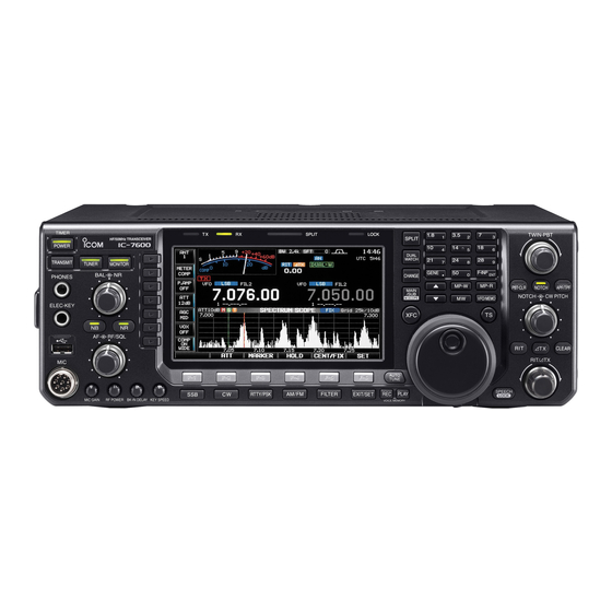
Page 4: Front Panel
• Unmount operation should be performed before re- moving the USB-Memory* (p.??). Connects a PC keyboard for RTTY and PSK op- erations. • USB keyboards* are supported. *: USB-Memory or USB keyboard is not supplied by Icom. - Page 5 Decreases mode as follows. (p. ??) SET MODE SETTING MODE AUTO RF GAIN + SQL Recommended level for an Icom microphone SSB, CW RF GAIN RF GAIN + SQL RTTY/PSK AM, FM RF GAIN + SQL MIC GAIN • When setting as RF gain/squelch control i AF CONTROL [AF] (inner control;...
- Page 6 PANEL DESCRIPTION Front panel (continued) TIMER SPLIT LOCK TWIN-PBT SPLIT HF/50MHz TRANSCEIVER POWER DUAL WATCH TRANSMIT TUNER MONITOR GENE F-INP CHANGE PHONES MP-W MP-R PBT - CLR NOTCH APF/TPF MAIN /SUB NOTCH CW PITCH M.SCOPE VFO/MEMO ELEC-KEY RF/SQL CLEAR RIT/ TX AUTO F- 1 F- 2...
- Page 7 PANEL DESCRIPTION MF3 (MULTI-FUNCTION 3 SWITCH) MF6 (MULTI-FUNCTION 6 SWITCH) P.AMP SWITCH (P.AMP) VOX SWITCH (VOX) Selects one of 2 receive RF preamps Push to turn the VOX function ON and or bypasses them. (p. ??) OFF during SSB, AM and FM mode •...
- Page 8 PANEL DESCRIPTION Front panel (continued) TIMER SPLIT LOCK TWIN-PBT SPLIT HF/50MHz TRANSCEIVER POWER DUAL WATCH TRANSMIT TUNER MONITOR GENE F-INP CHANGE PHONES MP-W MP-R PBT - CLR NOTCH APF/TPF MAIN /SUB NOTCH CW PITCH M.SCOPE VFO/MEMO ELEC-KEY RF/SQL CLEAR RIT/ TX AUTO F- 1 F- 2...
- Page 9 PANEL DESCRIPTION @1 MODE SWITCHES @5 VOICE MEMORY PLAYBACK SWITCH [PLAY] Selects the desired mode. (p. ??) (p. ??) • Announces the selected mode via the speech synthe- Push to playback the previously recorded audio sizer. (p. ??) for the preset time period. Push and hold for 1 sec.
- Page 10 (p. ??) • Switches between transmit frequency and receive • Icom’s triple band stacking register memorizes 3 fre- frequency when the split frequency function is ON. quencies in each band. (p. ??) After pushing [F-INP ENT], push a key on the Equalizes the sub readout frequency to the main keypad to enter a numeric frequency.
- Page 11 PANEL DESCRIPTION $0 PASSBAND TUNING CONTROLS [TWIN-PBT] $2 ∂TX SWITCH [∂TX] (p. ??) Push to turn the ∂TX function ON and OFF. (p. ??) • Use [RIT/∂TX] control to vary the ∂TX frequency. Adjusts the receiver’s IF filter “passband width” via Push and hold for 1 sec.
- Page 12 PANEL DESCRIPTION Front panel (continued) $7 $8 $9 %0 %1 TIMER SPLIT LOCK TWIN-PBT SPLIT HF/50MHz TRANSCEIVER POWER DUAL WATCH TRANSMIT TUNER MONITOR GENE F-INP CHANGE PHONES MP-W MP-R PBT - CLR NOTCH APF/TPF MAIN /SUB NOTCH CW PITCH M.SCOPE VFO/MEMO ELEC-KEY RF/SQL...
- Page 13 PANEL DESCRIPTION %3 CW PITCH CONTROL [CW PITCH] (outer control; Shifts the received CW audio pitch and the CW side tone pitch without changing the operating fre- quency. Higher frequency Lower frequency %4 MANUAL NOTCH FILTER CONTROL [NOTCH] (inner control; Varies the notch frequency of the manual notch fil- ter to reject an interfering signal while the manual notch function is ON.
-
Page 14: Rear Panel
CONVERTER And the modulation input level from USB jack can Used for transceive operation with another Icom be set in the ACC set mode item ‘USB MOD Level.’ CI-V transceiver or receiver. (p. ??) - Page 15 (p. ??) lower than 16 V DC/0.5 A (or 250 V AC, 200 mA with MOSFET switching). !4 ALC INPUT JACK [ALC] (p. ??) Connects to the ALC output jack of a non-Icom lin- ear amplifier.
-
Page 16: Lcd Display
PANEL DESCRIPTION LCD display @2 @3 q S/RF METER w IF FILTER INDICATOR (pgs. ??, ??) (p. ??) Shows the signal strength while receiving. Shows Shows the selected IF filter number. the relative output power, SWR, ALC, VD, ID or e QUICK TUNING INDICATOR (p. - Page 17 PANEL DESCRIPTION o RTTY TUNING INDICATOR @2 NOTCH INDICATOR (p. ??) Shows the tuning condition in RTTY mode. “ ” appears when the manual notch function is in use. This function is available in SSB, CW, !0 MODE INDICATOR RTTY, PSK and AM modes. Shows the selected mode.
-
Page 18: Screen Menu Arrangement
PANEL DESCRIPTION Screen menu arrangement The following screens can be selected from the start Pushing [EXIT/SET] several times returns to the start up screen. Choose the desired screen using the fol- up screen. See p. ?? for set mode arrangement. lowing chart. -
Page 19: Installation And Connections
final tran- sistors. In this case, an antenna tuner is useful to match the transceiver and antenna. Low SWR allows full power for transmitting. The IC-7600 has an SWR meter to monitor the antenna SWR continuously. -
Page 20: Required Connections
INSTALLATION AND CONNECTIONS Required connections D Front panel TIMER CW KEY SPLIT LOCK TWIN-PBT HF/50MHz TRANSCEIVER SPLIT POWER DUAL WATCH TRANSMIT TUNER MONITOR GENE F-INP CHANGE PHONES MP-W MP-R PBT-CLR NOTCH APF/TPF MAIN /SUB NOTCH CW PITCH M.SCOPE VFO/MEMO ELEC-KEY RF/SQL CLEAR RIT/ TX... -
Page 21: Advanced Connections
EXTERNAL SPEAKER Connects an external (pgs. ??, ??) (p. ??) preamp or lowpass filter. [ALC], [SEND] (p. ??) RX ANT IN/OUT must be SP-23 Used for connecting a activated in the antenna (option) non-Icom linear amplifier. set screen (p. ??). -
Page 22: Usb Connection
An USB keyboard* or an USB hub* can also be con- nected to the USB connector. * USB-Memory, USB keyboard or USB hub is not supplied by Icom. When the transceiver is connected to PC, an USB cable (third party) should be connected to the USB connector (B type) on the rear panel. -
Page 23: Power Supply Connections
• The [POWER] switch is OFF. • Output voltage of the power source is 12–15 V when you use a non-Icom power supply. • DC power cable polarity is correct. Red : Positive + terminal Black : Negative _ terminal... -
Page 24: Linear Amplifier Connections
16 V/0.5 A DC with initial setting, and 250 V/ RF OUTPUT RF INPUT 200 mA with “MOSFET” setting (see p. ?? for de- tails). Use an external relay unit if your non-Icom SEND linear amplifier requires control voltage and/or cur- rent greater than specified. Non-Icom linear amplifier... -
Page 25: Transverter Jack Information
D When connecting to the [USB] connector Connect an USB cable (third party’s) between the transceiver’s USB connector [USB] (B) on the rear panel and PC. (p. ??) • Icom HP (http://www.icom.co.jp/world/support/index.html) gives the USB driver and the installation guide download service. -
Page 26: Microphone Connector Information
CAUTION: DO NOT short pin 2 to ground as this can damage the internal 8 V regulator. DC voltage is applied to pin 1 for microphone operation. Use cau- tion when using a non-Icom microphone. Microphones q UP/DOWN SWITCHES [UP]/[DN] D HM-36 Change the selected readout frequency or memory channel. -
Page 27: Accessory Connector Information
INSTALLATION AND CONNECTIONS Accessory connector information ACC 1 PIN No. NAME DESCRIPTION SPECIFICATIONS “High” level : More than 2.4 V RTTY Controls RTTY keying “Low” level : Less than 0.6 V Output current : Less than 2 mA Connects to ground. Connected in parallel with ACC 2 pin 2. -
Page 28: Basic Operation
BASIC OPERATION Before first applying power Before first applying power, make sure all connec- After all connections have been done, set controls tions required for your system are complete by refer- and switches as shown in the figure below. ring to Chapter 2. : Max. -
Page 29: Selecting Vfo/Memory Mode
(p. ??) “VFO” indicator Memory channel number Main/Sub band selection MAIN The IC-7600 has 2 identical receivers, main and sub. /SUB M.SCOPE M.SCOPE The main band is displayed on the left hand side, and the sub band is displayed on the right hand side of the LCD. -
Page 30: Selecting An Operating Band
BASIC OPERATION Selecting an operating band The triple band stacking register provides 3 memories Band keys for each band key, storing frequency and mode infor- mation. This function is convenient when you operate 3 oper- ating modes on one band. For example, one register is used for a CW frequency, another for a SSB fre- quency and the other one for a RTTY frequency. -
Page 31: Frequency Setting
BASIC OPERATION Frequency setting The transceiver has several tuning methods for con- venient frequency tuning. D Tuning with the main dial q Push the desired band key on the keypad 1–3 Band keys times. • 3 different frequencies can be selected on each band with the band key. -
Page 32: D About 5 Mhz Band Operation (Usa Version Only)
* The FCC specifies center frequencies on the 5 MHz band. However, the IC-7600 displays car- rier frequency. Therefore, tune the transceiver to 1.5 kHz below the specified FCC channel center frequency. -
Page 33: D Selecting 1 Hz Step
BASIC OPERATION D Selecting 1 Hz step A minimum tuning step of 1 Hz can be used for fine tuning. q Push [TS] to turn the quick tuning function OFF. w Push and hold [TS] for 1 sec. to turn the 1 Hz tun- ing step ON and OFF. -
Page 34: D Band Edge Warning Beep
BASIC OPERATION D Band edge warning beep When you tune outside of an amateur band’s fre- quency range, a warning beep sounds. This function can be turned OFF in set mode, if desired. q Push [EXIT/SET] several times to close a multi- function screen, if necessary. -
Page 35: Operating Mode Selection
SSB (USB/LSB), SSB data (USB data/LSB data), CW, CW reverse (CW-R), RTTY, RTTY reverse (RTTY-R), PSK, PSK reverse (PSK-R), AM, AM data, FM and FM data modes are available in the IC-7600. Push the desired mode switch momentarily to select a mode of operation. -
Page 36: Squelch And Receive (Rf) Sensitivity
BASIC OPERATION Squelch and receive (RF) sensitivity Adjusts the RF gain and squelch threshold level. The squelch removes noise output from the speaker (closed position) when no signal is received. • The squelch is particularly effective for AM and FM. It is also available for other modes. -
Page 37: Volume Setting
Indicates the drain terminal voltage of the final amplifier MOSFETs. D Multi-function digital meter The IC-7600 can display the multi-function digital meter on the LCD display. This meter displays all transmit parameters simultaneously. q Push and hold [METER] (MF2) for 1 sec. to turn the multi-function digital meter ON. -
Page 38: D Meter Type Selection
BASIC OPERATION D Meter type selection A total of 3 meter types are available in the IC-7600— DISP Standard, Edgewise and Bar meters. Follow the instructions below for the meter type selec- tion. q Push [EXIT/SET] several times to return to normal screen, if necessary. -
Page 39: Basic Transmit Operation
BASIC OPERATION Basic transmit operation Before transmitting, monitor your selected operating frequency to make sure transmitting won’t cause interference to other stations on the same frequency. It’s good amateur practice to listen first, and then, even if nothing is heard, ask “Is the frequency in use?”... -
Page 40: D Drive Gain Adjustment
BASIC OPERATION D Drive gain adjustment The drive gain is active for all modes other than SSB mode with speech compressor OFF. Before transmitting, monitor your selected operat- ing frequency to make sure transmitting won’t cause interference to other stations on the same frequency. q Push [EXIT/SET] several times to return to normal screen, if necessary. -
Page 41: Receive And Transmit
RECEIVE AND TRANSMIT Functions for CW operation D About CW reverse mode CW-R (CW Reverse) mode uses the opposite side band to receive CW signals. Use when interfering signals are near a desired sig- Push nal and you want to use CW-R to reduce the interfer- ence. -
Page 42: D Apf (Audio Peak Filter) Operation
RECEIVE AND TRANSMIT D APF (Audio Peak Filter) operation The APF changes the audio frequency response by boosting a particular frequency to enhance a desired CW signal. q During CW mode, push [APF/TPF] to turn the audio peak filter ON and OFF. •... -
Page 43: Electronic Keyer Functions
RECEIVE AND TRANSMIT Electronic keyer functions The IC-7600 has a number of convenient functions for the built-in electronic keyer that can be accessed from the memory keyer menu. q During CW mode, push [EXIT/SET] several times KEYER to return to normal screen, if necessary. -
Page 44: D Memory Keyer Screen
RECEIVE AND TRANSMIT D Memory keyer screen Pre-set characters can be sent using the keyer send menu. Contents of the memory keyer are set using the edit menu. • Transmitting q During CW mode operation, push [KEYER] (F-3) KEYER −1 to select memory keyer screen. -
Page 45: D Editing A Memory Keyer
Contents • Pushing [DEL] (F-3) deletes a character and [SPACE] M1 CQ TEST CQ TEST DE ICOM ICOM TEST (F-4) inserts a space. y Repeat steps r and t to input the desired char- M2 UR 5NN acters. -
Page 46: D Contest Number Set Mode
RECEIVE AND TRANSMIT D Contest number set mode • Contest number set mode screen This menu is used to set the contest (serial) number KEYER and count-up trigger, etc. • Setting contents q During CW mode operation, push [KEYER] (F-3) to select memory keyer screen. - Page 47 RECEIVE AND TRANSMIT D Keyer set mode This set mode is used to set the memory keyer repeat CW KEY time, dash weight, paddle specifications, keyer type, etc. • Setting contents q During CW mode operation, push [KEYER] (F-3) to select memory keyer screen. w Push [EXIT/SET] to select memory keyer menu, then push [CW KEY] (F-4) to select keyer set mode.
- Page 48 RECEIVE AND TRANSMIT D Keyer set mode (continued) Paddle Polarity Normal This item sets the paddle dot-dash polarity. • Normal and reverse polarity can be selected. Keyer Type ELE-KEY This item selects the keyer type for [ELEC-KEY] • ELEC-KEY, BUG-KEY and Straight key can be connector on the front panel.
-
Page 49: Rtty (Fsk) Operation
RECEIVE AND TRANSMIT RTTY (FSK) operation A DSP-based high-quality Baudot RTTY encoder/ decoder is built-in to the IC-7600. When connecting a PC keyboard (p. ??), RTTY operation can be per- formed without an external RTTY terminal, TNC or If you would rather use your RTTY terminal or TNC, consult the manual that comes with the RTTY termi- nal or TNC. -
Page 50: D About Rtty Reverse Mode
RECEIVE AND TRANSMIT D About RTTY reverse mode Received characters are occasionally garbled when the received signal is reversed between Mark and Space tones. This reversal can be caused by incor- rect TNC connections, setting, commands, etc. To receive a reversed RTTY signals correctly, select Normal Reverse RTTY-R (RTTY Reverse) mode. -
Page 51: D Functions For The Rtty Decoder Indication
RECEIVE AND TRANSMIT D Functions for the RTTY decoder indication q Push a band key to select the desired band. DECODE WIDE w Push [RTTY/PSK] to select RTTY. Band keys • After RTTY mode is selected, push and hold [RTTY/ PSK] for 1 sec. -
Page 52: D Rtty Memory Transmission
RECEIVE AND TRANSMIT D RTTY memory transmission Pre-set characters can be sent using the RTTY mem- ory. Contents of the memory are set using the edit menu. DECODE TX MEM 1–4/5–8 q During RTTY mode operation, push [DECODE] (F-3) to select RTTY decode screen. w Push [TX MEM] (F-3) to select RTTY memory screen. -
Page 53: D Editing Rtty Memory
RTTY memory con- ↵73 GL SK↵ tents can also be edited from the keyboard. ↵CQ CQ CQ DE ICOM ICOM ICOM K↵ ↵MY TRANSCEIVER IS IC–7600 & ANTENNA IS A 3–ELEMENT TRIBAND YAGI.↵ ↵MY RTTY EQUIPMENT IS INTERNAL FSK... -
Page 54: D Rtty Decode Set Mode
RECEIVE AND TRANSMIT D RTTY decode set mode This set mode is used to set the decode USOS func- tion, time stamp setting, etc. WIDE • Setting contents q During RTTY mode operation, push [DECODE] (F-3) to select RTTY decode screen. w Push [<MENU1>] (F-1) to select the second RTTY decode menu, then push [SET] (F-5) to select RTTY decode set mode. - Page 55 RECEIVE AND TRANSMIT RTTY TX USOS Explicitly inserts the FIGS character even though it • ON : Inserts FIGS. is not required by the receiving station. • OFF : Does not insert FIGS. RTTY Auto CR+LF by TX Selects the automatic new line code (CR+LF) trans- •...
-
Page 56: D Data Saving
RECEIVE AND TRANSMIT D Data saving The contents of the RTTY memory/received signal The USB-Memory is not supplied by Icom. can be saved into the USB-Memory. q During RTTY decode screen indication, push SPACE [<MENU1>] (F-1) to select the RTTY decode sec- Symbol ond menu. -
Page 57: Psk Operation
RECEIVE AND TRANSMIT PSK operation A high-quality DSP-based PSK encoder/decoder is built-in to the IC-7600. When connecting a PC key- board (p. ??), PSK operation can be performed with- [TX] [RX] DECODE indicator indicator Band keys out PSK software installed on your PC. -
Page 58: D About Bpsk And Qpsk Modes
RECEIVE AND TRANSMIT D About BPSK and QPSK modes BPSK and QPSK modes are available for PSK. • BPSK (Binary Phase Shift Keying) mode is the most commonly used mode. • QPSK (Quadrature Phase Shift Keying) mode has error correction capability to provide better decoding than BPSK mode in marginal condition. -
Page 59: D Functions For The Psk Decoder Indication
RECEIVE AND TRANSMIT D Functions for the PSK decoder indication q Push a band key to select the desired band. w Push [RTTY/PSK] to select PSK. DECODE AFC/NET WIDE • After PSK mode is selected, push and hold [RTTY/ Band keys PSK] for 1 sec. -
Page 60: D Psk Memory Transmission
RECEIVE AND TRANSMIT D PSK memory transmission Pre-set characters can be sent using the PSK mem- ory. Contents of the memory are set using the edit menu. q During PSK mode operation, push [DECODE] (F-3) DECODE TX MEM 1–4/5–8 to select PSK decode screen. w Push [TX MEM] (F-3) to select PSK memory screen. -
Page 61: D Editing Psk Memory
Repeat steps r and t to input the desired char- ↵QSL UR 599 599 BK↵ acters. ↵QSL DE Icom Icom UR 599 599 BK↵ u Push [EXIT/SET] to set the contents and exit PSK ↵73 GL SK↵ memory edit screen. -
Page 62: D Psk Decode Set Mode
RECEIVE AND TRANSMIT D PSK decode set mode This set mode is used to set the decode USOS func- tion, time stamp setting, etc. WIDE • Setting contents q During PSK mode operation, push [DECODE] (F-3) to select PSK decode screen. w Push [<MENU1>] (F-1) to select the second PSK decode menu, then push [SET] (F-5) to select PSK decode set mode. - Page 63 RECEIVE AND TRANSMIT PSK Time Stamp (Frequency) Selects the operating frequency display for time • ON : Displays the operating frequency. stamp usage. • OFF : No operating frequency display. NOTE: The frequency won’t be displayed when “OFF” is selected in “PSK Time Stamp” as below left.
- Page 64 RECEIVE AND TRANSMIT D Data saving The contents of the PSK memory/received signal can The USB-Memory is not supplied by Icom. be saved into the USB-Memory. q During PSK decode screen indication, push SPACE [<MENU1>] (F-1) to select the PSK decode sec- Symbol ond menu.
-
Page 65: Repeater Operation
RECEIVE AND TRANSMIT Repeater operation A repeater retransmits a received signal on a differ- ent frequency. When using a repeater, the transmit frequency is shifted from the receive frequency by an offset frequency. A repeater can be accessed using split frequency operation with the transmit frequency shifted to the repeater's receive frequency. -
Page 66: Tone Squelch Operation
RECEIVE AND TRANSMIT Tone squelch operation The tone squelch opens only when receiving a sig- nal containing a matching subaudible tone. You can silently wait for calls from group members using the TONE same tone. q Set the desired frequency band and select FM mode. -
Page 67: Data Mode (Afsk) Operation
RECEIVE AND TRANSMIT Data mode (AFSK) operation When operating AMTOR or PACKET with your TNC and/or PC software, consult the manual that comes with the TNC and/or the software. q Connect a PC and TNC to the transceiver. Band keys (p. -
Page 68: Spectrum Scope Screen
The IC- 7600 has two modes for the spectrum display— one is center mode, and the other is fixed mode. In addition, the IC-7600 has a mini scope screen to save screen space. D Center mode Displays signals around the set frequency within the selected span. -
Page 69: D Fixed Mode
RECEIVE AND TRANSMIT D Fixed mode Displays signals within the specified frequency range. Conditions on the selected frequency band can be observed at a glance when using this mode. HOLD CENT/FIX q Push [EXIT/SET] several times to close a multi- function screen, if necessary. -
Page 70: D Mini Scope Screen Indication
RECEIVE AND TRANSMIT D Mini scope screen indication The mini scope screen can be displayed with another screen display, such as set mode menu, decode screen, memory list screen, etc. simultaneously. q Set the scope mode (center or fixed), marker, attenuator, span, etc. - Page 71 RECEIVE AND TRANSMIT D Scope set mode (continued) Scope during Tx (CENTER Type) Turn display of the transmit signal ON and OFF. NOTE: Transmit signal display is available for the center mode only. Max Hold Turn the peak level hold function ON and OFF. CENTER Type Display Filter Center Select the center frequency of the spectrum scope...
- Page 72 RECEIVE AND TRANSMIT D Scope set mode (continued) (± 25k) FAST Select the sweep speed for the ±25 kHz span selec- tion from SLOW, MID and FAST. (± 50k) FAST Select the sweep speed for the ±50 kHz span selec- tion from SLOW, MID and FAST.
- Page 73 RECEIVE AND TRANSMIT D Scope set mode (continued) ( 8.00 − 11.00) 10.100 − 10.150 MHz Set the scope edge frequencies for fixed mode • Set the frequencies within 8.000 to 11.000 MHz scope when the 8 to 11 MHz band is selected. range in 1 kHz steps.
- Page 74 RECEIVE AND TRANSMIT D Scope set mode (continued) (26.00 − 30.00) 28.000 − 28.500 MHz Set the scope edge frequencies for fixed mode • Set the frequencies within 26.000 to 30.000 MHz scope when the 26 to 30 MHz band is selected. range in 1 kHz steps.
- Page 75 RECEIVE AND TRANSMIT Preamplifier The preamp amplifies received signals in the receiver front end, to improve the S/N ratio and sensitivity. Set this to preamp 1 or preamp 2 when receiving weak signals. P.AMP Push [P.AMP] (MF3) several times to set the pre- amp OFF, preamp 1 ON or preamp 2 ON.
-
Page 76: D Rit Monitor Function
RECEIVE AND TRANSMIT RIT function The RIT (Receive Increment Tuning) function com- pensates for off-frequency operation of the received station. The function shifts the receive frequency up to ±9.99 kHz in 10 Hz steps without moving the trans- mit frequency. q Push [RIT] to turn the RIT function ON and OFF. -
Page 77: Agc Function
RECEIVE AND TRANSMIT AGC function The AGC (auto gain control) controls receiver gain to produce a constant audio output level even when the received signal strength varies greatly. The transceiver has 3 preset AGC characteristics (time constant: fast, mid, slow) for non-FM mode. The FM mode AGC time constant is fixed as ‘FAST’... -
Page 78: Twin Pbt Operation
IF frequency slightly outside of the IF filter passband to reject interference. The IC-7600 uses DSP for the PBT function. Moving both [TWIN-PBT] controls to the same position shifts the IF both above and below the received frequency. -
Page 79: D If Filter Selection
RECEIVE AND TRANSMIT IF filter selection The transceiver has 3 passband width IF filters for each mode. For SSB, CW and PSK modes, the passband width can be set within 50 to 3600 Hz in 50 or 100 Hz steps. A total of 41 passband widths are available. For RTTY mode, the passband width can be set within 50 to 2700 Hz in 50 or 100 Hz steps. -
Page 80: D Roofing Filter Selection
RECEIVE AND TRANSMIT D Roofing filter selection ROOFING The IC-7600 has 3, 6 and 15 kHz roofing filters at the 1st IF frequency. The roofing filter provides interfer- ence reduction from nearby strong signals. q Push and hold [FILTER] for 1 sec. to enter filter set screen. - Page 81 RECEIVE AND TRANSMIT D Filter shape set mode (continued) (600Hz – ) SHARP Select the filter shape for SSB mode in HF bands. The set filter shape is automatically used only when the IF filter is set to 600 Hz or wider. SSB-D (600Hz –...
-
Page 82: Dualwatch Operation
RECEIVE AND TRANSMIT Dualwatch operation Dualwatch monitors 2 frequencies simultaneously. During dualwatch, both frequencies should be on the same band, because the bandpass filter in the RF cir- cuit is selected for the main readout frequency. q Set a desired frequency into the main band. w Push and hold [DUALWATCH] for 1 sec. - Page 83 RECEIVE AND TRANSMIT • Scanning during dualwatch Scanning operates only for the main readout. To operate the scan during dualwatch, scan on the main readout and use the sub readout for your QSO using both dualwatch and split frequency operation. q Program the desired programmed scan edges in DUAL WATCH...
-
Page 84: Noise Blanker
RECEIVE AND TRANSMIT Noise blanker <MODE> SSB/CW/RTTY/PSK/AM The noise blanker eliminates pulse-type noise such as the noise from car ignitions. The noise blanker is not available for FM mode. Push [NB] to turn the noise blanker function ON and OFF. •... -
Page 85: Noise Reduction
RECEIVE AND TRANSMIT Noise reduction The noise reduction function reduces random noise components and enhances desired signals which are buried in noise. The DSP performs the random noise reduction function. q Push [NR] to turn the noise reduction ON. • The indicator on this switch lights green. w Rotate the [NR] control to adjust the noise reduc- [NR] tion level. -
Page 86: Notch Function
RECEIVE AND TRANSMIT Notch function This transceiver has auto and manual notch func- tions. The auto notch function uses DSP to automatically attenuate up to 3 beat tones, tuning signals, etc., even if they are moving. The manual notch can be set to attenuate a frequency via the [NOTCH] control.
Need help?
Do you have a question about the IC-7600 and is the answer not in the manual?
Questions and answers