Table of Contents
Advertisement
Quick Links
Advertisement
Table of Contents

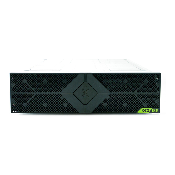
Summary of Contents for X-IO ISE-2 Series
- Page 2 X-IO Corporation 9950 Federal Drive, Suite 100 Colorado Springs, CO 80921-3686 www.X-IO.com Main: 719.388.5500 Fax: 719.388.5300 X-IO Customer Support at 1.800.734.4716 IMPORTANT NOTICE This manual is provided to you by Xiotech Corporation (“Xiotech”), and your receipt and use of this manual is subject to your agreement to the following conditions: •...
-
Page 3: Table Of Contents
Table of Contents ISE User Guide Table of Contents Preface ..............1 Conventions . - Page 4 ISE User Guide Table of Contents Management Console ............22 Orchestrator .
- Page 5 Table of Contents ISE User Guide Configuring Storage ............55 Storage Pools and Volumes .
- Page 6 ISE User Guide Table of Contents Using Orchestrator ............91 Using Web-Mgt .
- Page 7 Table of Contents ISE User Guide Seating FRUs ............. . . 147 SFP .
- Page 8 ISE User Guide Table of Contents Page vi 160337-000 Rev D, 30 September, 2013 Xiotech—Proprietary...
-
Page 9: Preface
Arial, 9 pt, Bold Variable, represents text that must be entered <Courier New, 10 pt, Bold, Italic> Table 1: Document Conventions Related Documents X-IO X-IO The following documents, available for download from the Support Center Web site, http://www. .com/ supportmatrix, provide additional information about the ISE: •... - Page 10 ISE User Guide Preface • ISE Manager User Guide • Orchestrator User Guide • ISE Analyzer User Guide Page 2 160337-000 Rev D, 30 September, 2013 Xiotech—Proprietary...
-
Page 11: Introduction
Introduction ISE User Guide Introduction The ISE is a high-density, fully redundant, rack-mountable storage device that integrates enterprise-class drives with advanced array controllers and environmental support components to provide an extremely reliable self-contained storage unit that outperforms more traditional storage sub-systems. As a fully redundant unit, the ISE consists of pairs of active components;... -
Page 12: Components
ISE User GuideUser Guide Introduction g. Background parity scan: Provides enhanced data integrity by employing an embedded function to auto- matically check all data for RAID parity consistency and flag inconsistent data with a media error. h. Embedded Web service: Built-in Web browser and management tool, Orchestrator, that facilitates control of ISE systems, eliminating the need for a separate management server. -
Page 13: Tmra
• SCSI Architecture Model 3 (SAM-3), Revision 13 of the SCSI specifications Extremely high drive operability is provided by the ISE Managed Reliability feature, which corrects many drive X-IO failures without operator intervention. A data migration utility is available through Customer Support if an entire DataPac requires replacing. -
Page 14: Reduced Air Flow
ISE User GuideUser Guide Introduction Reduced Air Flow Installation of the equipment in a rack should be such that the amount of air flow required for safe operation of the equipment is not compromised. Mechanical Loading Mounting of the equipment in a rack should be such that the rack and supporting floor structure weight capacities are not compromised. - Page 15 Introduction ISE User Guide • CSA C108.8-M1983 • CISPR 22 • EN 50082-1 • EN 55024 This Class A digital apparatus complies with Canadian ICES-003. Cet appareil numérique de classe A est conforme à la nome NMB-003 du Canada. Xiotech—Proprietary 160337-000 Rev D, 30 September, 2013 Page 7...
-
Page 16: Rack Loading
ISE User GuideUser Guide Introduction Figure 2. Declaration of Conformity Rack Loading An ISE Storage Blade can weigh from 100 lbs. to 130 lbs.; care must be taken to mount the ISE Storage Blade on a rack certified to support the models being installed as well as the attached hardware load. Page 8 160337-000 Rev D, 30 September, 2013 Xiotech—Proprietary... -
Page 17: Environmental Specifications
Introduction ISE User Guide Environmental Specifications Environmental specifications for the ISE Storage Blade are presented in this section. Dimensions The ISE Storage Blade dimensions are shown in the figure below. Figure 3. Front View with Dimensions (without Bezel) For reference, the ISE, with bezel installed, is shown in the figure below. Figure 4. -
Page 18: Site Requirements
ISE User GuideUser Guide Introduction Site Requirements The following tables present crucial environmental requirements for the ISE Storage Blade. Environment Requirement Operating temperature 10–35 degrees C Operating humidity 20–80% (Non-condensing) Operating altitude -1,000.6562–10,000 feet (-305–3,048 meters) Heat dissipation 2,050 btu per hour Loading weight Minimum DataPac (varies by model) -
Page 19: Installation
The ISE Storage Blade is a 3U, rack-optimized unit for installation into a server rack using the supplied custom rails and conforming to the specifications defined in this section. Before installation, it is a good practice to www.X-IO.com review the support matrix at for the latest information on supported configurations. -
Page 20: Rack Ise Chassis
ISE User Guide Installation Rack ISE Chassis The ISE chassis should be installed using the supplied rail kit into a rack before inserting the DataPacs as described here. Install Rail Kit Before an ISE Storage Blade can be installed in a rack, the custom rails must be installed. The custom rail kit mounts easily into both round-holed and square-holed racks. - Page 21 Installation ISE User Guide Figure 7. Installed Rail Kits Square–Holed Rack Mounting To install the adjustable rail kit into a square–holed rack, do the follow- ing: 1. Remove the rail kit with anchoring screws from its packaging (Figure 6 on page 12). 2.
-
Page 22: Install Ise Chassis
ISE User Guide Installation Install ISE Chassis The ISE chassis can be installed into a rack as it is in the shipping box before inserting the DataPacs as shown. The chassis as it is shipped weighs about seventy-three pounds and it is recommended that two peo- ple co-lift the chassis from the collapsed shipping carton and slide it into the rack. -
Page 23: Install Datapacs
Installation ISE User Guide Install DataPacs The ISE Storage Blade ships with two DataPacs or one DataPac and one DataPac Filler. The bay to left of the supercapacitor bays must always be populated with a DataPac. CAUTION—Handling DataPacs DataPac units are delicate and should always be handled with care. This is extremely important during the unpacking of DataPacs and subsequent handling leading to DataPac insertion into the chassis. -
Page 24: Single Datapac Installation
ISE User Guide Installation Single DataPac Installation For single DataPac installations, the DataPac must be installed to the left of the supercapacitor bays and the DataPac Filler must be installed to the right of the supercapacitor bays. Figure 12. ISE Chassis Front View—DataPac and Supercapacitor Insertion Install Supercapacitors The supercapacitors come pre-installed in the ISE chassis. -
Page 25: Install Mrcs
Installation ISE User Guide Figure 13. Rear View—Power Supply, MRC Insertion Install MRCs The MRCs come pre-installed in the ISE chassis. In the event there is a need to install an MRC, insert the unit gently into the chassis from the rear, oriented as shown in Figure 13 and with the latch handle fully open, push- ing firmly until the MRC seats. - Page 26 ISE User Guide Installation Figure 15. Snap Bezel Into Place Figure 16. Bezel Installed Page 18 160337-000 Rev D, 30 September, 2013 Xiotech—Proprietary...
-
Page 27: Recommended Cabling
Installation ISE User Guide Recommended Cabling Cabling an ISE involves attaching the power cords, Ethernet cables, service console cable (one), and Fibre Channel cables to the associated connectors on the ISE in a manner similar to that shown, figures 18 and 19. The important issue with cabling is to run the cables with enough slack to permit the hot-replacement of any component without interruption in ISE data services. -
Page 28: Storage Area Network (San)
ISE User Guide Installation Storage Area Network (SAN) In a SAN environment, the ISE connects to a host through the fabric (see the online compatibility matrix at ) and its Fibre Channel ports. In this network-attached environment, the ISE Stor- http://support.XIOstorage.com age Blade management interfaces are network accessible through the Ethernet ports. -
Page 29: Direct Attach (Das)
Installation ISE User Guide Direct Attach (DAS) An ISE can attach directly to a host through the Fibre Channel ports (see the online compatibility matrix at ). Below is an example of direct attach (or direct connect) of an ISE to a host. http://support.XIOstorage.com Notice that the cables are routed to avoid blocking hot-replacement of components. -
Page 30: Service Console
ISE User Guide Installation SFP Installation When additional SFP (Small-Form-Factor Pluggable) Fibre Channel connector modules are purchased, instal- lation is required. Install SFP modules using the following procedure: 1. Remove the protective plug from a port on an ISE MRC—three ports are available on each MRC. 2. -
Page 31: Fibre Channel Connectivity
ISE User Guide Fibre Channel Connectivity The ISE can connect to a host directly or through a Fibre Channel switch (see the online compatibility matrix at X-IO .com). To facilitate Fibre Channel connectivity, the ISE interfaces are designed to conform to http://support. -
Page 32: Ise Ip Addresses
If there are any amber LEDs lit, follow the guide below for the appropriate action. Component Corrective Action Contact X-IO Customer Support for a replacement component and then follow the procedure in the ISE- Supercapacitor 2 User Guide. Contact X-IO Customer Support for a replacement component and then follow the procedure in the ISE- Power Supply 2 User Guide. -
Page 33: Determine Ip Addresses
Installation ISE User Guide Determine IP Addresses To determine whether the ISE is using DHCP or a default IP address, enter the show network command. The network settings are displayed as shown in figure 21. Figure 21. Show Network Command Figure 22. -
Page 34: Changing Network Settings To Static (Optional)
Installation Complete The ISE installation is complete; the service console should be logged out of and a management interface con- nection opened. The three management interfaces, accessible through the network, are: X-IO • Orchestrator storage management and provisioning service X-IO •... -
Page 35: Web Management Interface
The Command Line Interface, described throughout this document, can be used to configure, monitor, and manage the ISE. Additional Options There are a number of additional options available for the ISE. Some of these (see “Related Documents” on page 1) are: X-IO • ActiveWatch—Part of an available Customer Support service •... - Page 36 ISE User Guide Installation Page 28 160337-000 Rev D, 30 September, 2013 Xiotech—Proprietary...
-
Page 37: Management Tools
Management Tools ISE User Guide Management Tools The ISE provides three methods to manage its configuration and operation: X-IO • Web-based Management Interface (Web-Mgt) X-IO • Orchestrator site-wide ISE management tool X-IO • Command Line Interface (CLI) This chapter presents the requirements and connection procedures for these methods. -
Page 38: Browser Requirements
ISE User Guide Management Tools Browser Requirements The remote Web browser used to manage the ISE can be on any computer on the Local Area Network and must meet the following requirements. Classic Web Interface (Web-Mgt): • Browsers: Internet Explorer 6.0 and later, Opera 9.5 and later, Safari 3.1 and later •... - Page 39 Management Tools ISE User Guide Element Name Description Navigation bar Horizontal bar with navigation drop-down menus Left navigation pane Tree format navigation to detailed component information Detail pane Main area of view containing the view details Drop-down menu Drop-down menu activated by hovering the pointer over a navigation bar item Current status Dynamic display of the system status (Operational here) Orchestrator UI...
-
Page 40: Logging In
ISE User Guide Management Tools Logging In This section describes the steps to log into the Web management tools. The user ID is a (case dministrator dependent) and the default password for the first-time login, set by manufacturing, is administrator. The password reverts to this default upon a reset to factory settings, during an ISE reformat (see “Reformat an ISE”... -
Page 41: Logging Out
(Figure 25 on page 30 and Figure 26 on page 31). logout 2. To exit from the Web-Mgt, click the browser close button and the browser window closes. Switching to Orchestrator X-IO To use Orchestrator, follow the steps below and refer to the Orchestrator User Guide: 1. Click in the left navigation pane (Figure 25 on page 30). -
Page 42: Site Index And Help
ISE User Guide Management Tools 3. Click to confirm the switch and the switch delay is marked by the screen shown below. Figure 30. Switch to Orchestra Delay This screen indicates “Switching to Orchestrator UI...page will automatically redirect in a few moments.” 4. -
Page 43: Command Line Interface
Management Tools ISE User Guide Command Line Interface The ISE contains an embedded Command Line Interface (CLI) that responds to commands entered at the CLI prompt on a remote console or invoked through a script. Standard command line protocol (such as terminating a command line with ) applies. - Page 44 ISE User Guide Management Tools Page 36 160337-000 Rev D, 30 September, 2013 Xiotech—Proprietary...
-
Page 45: Power-Up, Shutdown, Restart
Power-up, Shutdown, Restart ISE User Guide Power-up, Shutdown, Restart This chapter describes the power-up, shutdown, and restart functions of the ISE and details the steps to perform them: • Power-up (see “Power On State” on page 37) • Shutdown (see “Shutdown” on page 39) •... -
Page 46: Power Off State
ISE User Guide Power-up, Shutdown, Restart Power Off State Table 9 on page 38An ISE in the powered off state is totally without AC power. That is, all ISE components are without power and all LEDs are off. To place the ISE in the power-off mode, put both power supply switches into the position. -
Page 47: Shutdown
Power-up, Shutdown, Restart ISE User Guide Boot Type Conditions Inducing Boot Type Characteristics ISE resets some hardware subcomponents and reloads software and firmware Effects on outstanding host I/O requests: Firmware upgrade • One MRC warm boots, and the surviving MRC processes all Warm boot A few firmware exceptions causing sys- host requests with no impact on host... - Page 48 ISE User Guide Power-up, Shutdown, Restart To restart the ISE from the Orchestrator, Web-Mgt, or CLI, follow the procedure detailed in “Restart” on page 125. When an ISE is restarted, it performs a cold boot. Boot types are summarized in Table 10 on page 39.
-
Page 49: Initialize And Configure
Initialize and Configure ISE User Guide Initialize and Configure This chapter details the procedures to initialize the ISE, customize the system parameters, and configure the hosts, storage, and other customizing elements. The steps to initialize and configure an ISE using Orchestrator, the Web management interface (Web-Mgt), and the CLI are presented here. -
Page 50: Orchestrator
ISE User Guide Initialize and Configure Orchestrator Connect and log into an ISE using Orchestrator. The monitored ISEs are listed in the left navigation pane in the form of a navigation tree. Select an ISE and the status summary (Figure 33) is displayed in the details pane. is shown adjacent to and at the top of the temperature gauge. -
Page 51: Web-Mgt
Initialize and Configure ISE User Guide Web-Mgt Connect to the ISE using the Web-Mgt (“Web-Based Management” on page 29 for details). After login (first- time) to an un-initialized ISE, the view is presented (see “ISE System Monitoring” At-A-Glance Status Summary on page 103). - Page 52 ISE User Guide Initialize and Configure From the Initial Spare Configuration view, the following options are available: a. Initialize the ISE and the storage pools. b. Update the ISE firmware. This option is used by a network administrator installing a new ISE and must upgrade the firmware to the latest version before any configuration of that ISE.
-
Page 53: Factory State Reset
Initialize and Configure ISE User Guide Figure 36. Upload–Upgrade Firmware 2. To perform the update, follow the procedure detailed in “MRC Firmware Upgrade” on page 129; to skip the upgrade and return to the view, click the browser’s button. Initial Spare Configuration Back Factory State Reset An initialized ISE can be returned to a partial factory-ship state using the uninitialize (... - Page 54 ISE User Guide Initialize and Configure The ISE 7-Series is initialized with one pool distributed across two DataPacs. To initialize the ISE and the storage pools after skipping the initialization prompt, use the initialize command with no parameters. View the sparing percentage in effect on a system that has already been initialized by using either of the following commands: •...
-
Page 55: System Parameters
Initialize and Configure ISE User Guide System Parameters The configurable ISE system parameters—factory settings—should be reviewed and changed as needed. Discussed here are: • Using the Orchestrator interface, detailed in the Orchestrator User Guide • Using the Web-Mgt interface as detailed in “Web-Mgt” on page 47 •... -
Page 56: Command Line Interface (Cli)
ISE User Guide Initialize and Configure Setup Menu Options Parameters Description System Name “System Name” on page 49 Address “Address” on page 50 Location “Location” on page 50 Syste> m >system info Contact Name “Contact Name” on page 50 Contact Phone “Contact Phone”... -
Page 57: Ise System Parameters Detailed
Initialize and Configure ISE User Guide 3. Continue to set parameters until all desired changes are complete (use the up arrow key to retrieve previ- ous entries). Parameters Displayed Through the Command show ise Parameter Command to Set Additional Description “System Name”... - Page 58 ISE User Guide Initialize and Configure Address The Address is an optional user-defined address for an ISE, defining a physical address, building, or any address string. The address is any alphanumeric string of up to sixty characters. Embedded blanks and special characters (excepting “Reserved Characters”...
- Page 59 Initialize and Configure ISE User Guide CLI: To display the Contact Phone from the CLI, use the show ise command. To set the Contact Phone from the CLI, use the configure --phone=<contact_phone> command (see Figure 13 on page 49). If the contact phone is to contain embedded blanks, enclose the character string in quotation marks as shown in the following example: configure --phone=<“contact phone”>...
- Page 60 ISE-2, Hyper ISE, and ISE 7-Series: Speeds of 4 and 8 Gbs are supported on the individual ports when specified otherwise all ports are the same, Fibre Channel activity occurs at the selected speed (see support matrix at www.X-IO.com). •...
-
Page 61: Snmp Setup
Initialize and Configure ISE User Guide Web-Mgt: This parameter is accessed using the Web-Mgt through the >> option as Environment described in Step 4 of “Setup Menu Options” on page 48. CLI: To control this parameter using the CLI, use the configure --fcspeed=<Auto|1|2|4> command (see “CLI—System Parameters”... - Page 62 ISE User Guide Initialize and Configure Web-Mgt: The SNMP settings, contact information, and MIB root OID are accessible through the Web-Mgt only. To customize these parameters, use the procedures detailed in “Web-Mgt” on page 47, selecting snmp from the drop-down menu shown in Figure 37 (page 47). SNMP parameters may be changed at setup System any time.
-
Page 63: Cli: Snmp Trap Settings
Initialize and Configure ISE User Guide 3. If necessary, select addresses in the Address List for deletion or editing: • To delete an address from the Address List, select it and click TRL or HIFT fort multiple DELETE lines). • To edit an address in the Address List, select it and click . - Page 64 ISE User Guide Initialize and Configure The Orchestrator interface (see the Orchestrator User Guide) provides storage pool management through the following select strings: >> >> >> All Devices ise_name Storage View Storage Pools >> >> >> All Devices ise_name Storage View Volumes >>...
- Page 65 Initialize and Configure ISE User Guide Figure 38. Web-Mgt—ISE-2 Storage Pool Information Figure 39. Web-Mgt—ISE 7-Series Storage Pool Information From the CLI, obtain storage pool information using the show pool command. Xiotech—Proprietary 160337-000 Rev D, 30 September, 2013 Page 57...
-
Page 66: Creating Volumes
ISE User Guide Initialize and Configure Creating Volumes This section details the steps to create volumes using the Web-Mgt and the CLI. Orchestrator To create volumes using the Orchestrator, select >> >> >> then All Devices ise_name Storage View Volumes click OLUME . - Page 67 Initialize and Configure ISE User Guide 6. If the volume is not intended to consume the remaining capacity shown in the field, Capacity in Gigabytes enter the intended capacity for the volume being created. If no hosts have been created, no entries appear in the list.
-
Page 68: Command Line Interface
ISE User Guide Initialize and Configure Command Line Interface To create volumes using the Command Line Interface (CLI), follow the steps below. Cache mode, volume-host mapping, LUN number, and volume size can be modified after the Note. volume is created. To view the remaining capacity for volumes of each RAID type within each pool, type show pool. -
Page 69: Creating Hosts
Initialize and Configure ISE User Guide Creating Hosts Creating hosts using the Web-Mgt and the CLI is detailed in “Web-Mgt” below and “Command Line Interface (CLI)” on page 63 respectively. LUN assignments can be changed using the DIT Web-Mgt interface to avoid default luns assignments (see Figure 59 on page 87). - Page 70 ISE User Guide Initialize and Configure 5. Click to add the selected HBA ports to the Selected HBA Ports list. The host consists of the ports in the Selected HBA Ports list after is clicked. SUBMIT 6. Select the volumes to map to this host from the list.
- Page 71 Initialize and Configure ISE User Guide Command Line Interface (CLI) To create a host using the CLI, use the create host command with the options shown in Table 18. To see a list of assigned and unassigned HBA port WWIDs, enter the show hba command. If a name is not specified, the CLI auto-generates a name in the format Hostnn, where nn is an incrementing number starting from .
-
Page 72: Mapping Volumes And Hosts
ISE User Guide Initialize and Configure Mapping Volumes and Hosts This section details mapping volumes and hosts using the Web-Mgt and the CLI. When presenting a volume to a host, a mapping between that host and that volume is created. Each time a mapping is made, the ISE assigns an incrementing LUN number (starting with 0) for the volumes seen by that host. - Page 73 Initialize and Configure ISE User Guide The ISE creates the mapping and displays a confirmation similar to that shown in the figure (46) below. Presenting 'Volume03' to 'Prod01': OK Presenting 'Volume03' to 'Prod02': OK Figure 46. Volume Host Mapping After the initial volume-host mapping scheme has been created, it can be modified or deleted at any time using the CLI commands detailed in “Modify Volume–Host Mappings”...
- Page 74 ISE User Guide Initialize and Configure Page 66 160337-000 Rev D, 30 September, 2013 Xiotech—Proprietary...
-
Page 75: Ise Management
ISE Management ISE User Guide ISE Management This chapter details the various aspects of managing an ISE configuration: • System and SNMP settings (“Modify System, SNMP” on page 67) • ISE Analyzer (“ISE Analyzer Software Service” on page 68 and “Subscription Function” on page 68) •... -
Page 76: Ise Analyzer Software Service
Alerts: Notifications of specific events site-selected to track and notify a monitoring destination works in conjunction with ActiveWatch by monitoring ActiveWatch data in ISE Analyzer Software Service X-IO real time. ActiveWatch delivers diagnostic information to Customer Support (Support) collects daily... -
Page 77: Enable Subscriptions
ISE Management ISE User Guide Enable Subscriptions ships with a default destination address and the subscription function ISE Analyzer Software Service disabled. To use the , subscription must be enabled. This destination uses a ISE Analyzer Software Service secure SSL connection. When enabling a subscription to the , it may be necessary to configure the site ISE Analyzer Software Service... -
Page 78: Enable Local Subscriptions
ISE User Guide ISE Management The Create New Subscription page is displayed as shown in Figure 48. Figure 48. Enable ISE Analyzer Service Subscription Subscribing: 1. Enter an IP address. ISE Analyzer Software Service 2. Click LERT to subscribe to Alerts. 3. -
Page 79: View Subscriptions
ISE Management ISE User Guide The range for the -interval option is 15 to 1440 minutes. For Telemetry it is recommended that the interval be allowed to default to 1440. For example, the following command creates a subscription with an IP address destination of 10.20.30.40 and an interval of 8 hours (720 minutes). -
Page 80: Modify Subscription
ISE User Guide ISE Management Modify Subscription The interval for Telemetry and General Update subscriptions can be modified. Alert subscriptions do not have an interval. Notes: The interval for Telemetry and General Update subscriptions can be modified, but Alert subscription inter- vals cannot be modified. -
Page 81: Disable Subscriptions
ISE Management ISE User Guide Disable Subscriptions Once a subscription to has been enabled, it can be disabled using either the ISE ISE Analyzer Software Service Web Interface or the CLI as described below. Orchestrator To disable ActiveWatch subscriptions using the Orchestrator, select >>... -
Page 82: Send General Update File
ISE User Guide ISE Management 10.20.30.40:443, type=general update, enable=false, interval=720, Last Sent= 14- Sep-2010 09:17:26 10.20.30.40:443, type=alert, enable=true Send General Update File An immediate transmission of the General Update file to the managed by ISE Analyzer Software Service Support or the locally installed can be directly initiated through the CLI. -
Page 83: Cli
Telemetry file to all subscriptions. ISE Analyzer Software Service telemetry send -ipaddress=10.20.30.40 sends the Telemetry file to 10.20.30.40. X-IO Do not use the telemetry send -file unless instructed to by Customer Support. Note. Volume and Host Configuration... -
Page 84: Web-Mgt, Modify Volume
ISE User Guide ISE Management page appears with the volume names in the first column of the Detailed Volume Information Volume section below (see reference 2 in Figure 50). Information Figure 50. Detailed Volume Information Web-Mgt, Modify Volume To modify volume configurations, open the view (Figure 51 on page 77). -
Page 85: Orchestrator, View Host Configuration
ISE Management ISE User Guide Changes do not take effect until (bottom of the view) is clicked. Save Changes Figure 51. Detailed Volume Information Orchestrator, View Host Configuration To view ISE host configuration using the Orchestrator, select >> >> >> All Devices ise_name Host View... -
Page 86: Web-Mgt, View Host Configuration
ISE User Guide ISE Management Web-Mgt, View Host Configuration To view ISE host configurations, open the page as follows: Detailed Host Information 1. Select >> from the navigation bar on any Web-Mgt page and the view Hosts summary Host Summary opens. - Page 87 ISE Management ISE User Guide Changes do not take effect until (bottom of the view) is clicked. Save Changes Figure 53. Detailed Host Information Xiotech—Proprietary 160337-000 Rev D, 30 September, 2013 Page 79...
-
Page 88: Cli, View-Modify Volume Configuration
ISE User Guide ISE Management CLI, View–Modify Volume Configuration View existing volumes from the CLI using the show volume command. The Local ID (LDID) number provides the means to map the relevant events in the Event Log to the Note. name given the volume during volume creation. -
Page 89: Cli, View-Modify Host Configuration
ISE Management ISE User Guide CLI, View–Modify Host Configuration View existing hosts through the CLI using the show hosts command and existing HBA port WWIDs using the show hba command. View any mappings by entering show hosts or show volumes. Change the host name, its operating system, the member HBA port WWIDs, and its optional comment from the CLI using the modify command with the options shown in Figure 21. -
Page 90: Modify Volume-Host Mappings
ISE User Guide ISE Management Modify Volume–Host Mappings The volume-host mapping scheme can be modified at any time after initial configuration. The Orchestrator, Web-Mgt, and the CLI can be used as follows: • Modify volumes and hosts with the Orchestrator (see Orchestrator User Guide). •... - Page 91 ISE Management ISE User Guide view (Figure 55) or the view Volume-Host Mapping Information Host-Volume Mapping Information (shown in Figure 56 on page 83) appears (see “View, Modify LUNs” on page 85 for more information on LUN mapping). Figure 55. Volume-Host Mapping Information–Delete Figure 56.
-
Page 92: Cli, Modify Volume-Host Mapping
ISE User Guide ISE Management CLI, Modify Volume–Host Mapping The steps involved in modifying host mappings are presented in “Mapping Volumes and Hosts” on page 64. Deleting a mapping removes visibility from the host to the volume. The volume–host mapping scheme can be modified at any time through the CLI by first deleting the current mapping using the unpresent command with the options shown in Table 22. -
Page 93: View, Modify Luns
ISE Management ISE User Guide View, Modify LUNs LUNs are created during host-volume mapping. Each time a mapping is made, the ISE assigns an incrementing LUN number (starting with 0) to the volumes seen by that host. For example, in the configuration shown in Figure 55 on page 83, is the first volume mapped to , so it is... - Page 94 ISE User Guide ISE Management page (shown in Figure 57 below) appears. Volume Summary Figure 57. Volume Summary–Edit Figure 58. Volume–Host Mapping Details Page 86 160337-000 Rev D, 30 September, 2013 Xiotech—Proprietary...
-
Page 95: Cli View, Modify Luns
ISE Management ISE User Guide page (shown in Figure 59 below) appears. In this example, host CC1R1_P1 is Detailed Host Information mapped to ISE1_V1 as LUN1 and to ISE1_V2 as LUN2. Figure 59. Host Summary–Edit Figure 60. Host–Volume Mapping Details 2. -
Page 96: Re-Size Luns
ISE User Guide ISE Management To change the LUN assignments using the CLI, use the present command described in “Modify Volume– Host Mappings” on page 82, adding the :<lun> option after each host name. For example, the following command changes the LUN through which Volume03 is mapped to host Prod02 to LUN7 from whatever LUN was previously used: present --volume=Volume03 Prod02:7 Mappings do not have to be removed before changing a LUN. - Page 97 ISE Management ISE User Guide pleted with the page showing the new size in the column. Volume Summary Size Figure 61. Volume Summary Page–Segment Xiotech—Proprietary 160337-000 Rev D, 30 September, 2013 Page 89...
- Page 98 ISE User Guide ISE Management Figure 62. LUN Re-size—Final Step CLI, Resize LUNs Follow the steps below to resize LUNs using the Command Line Interface. 1. At the prompt, enter modify --volume=volume1 --expand=x, where volume1 is the volume to be re-sized and x is the new size in GB.
-
Page 99: Deleting Volumes
ISE Management ISE User Guide Deleting Volumes When a volume is no longer needed, its capacity can be returned to the storage pool by deleting the volume. To do so using the Web-Mgt, follow these steps. WARNING: Ensure that the data on the volumes is of no further use before deleting the volume. 1. -
Page 100: Ise Systems Dashboard
ISE User Guide ISE Management ISE Systems Dashboard The ISE Systems dashboard provides the means to manage and monitor multiple ISEs from within a single ISE. Orchestrator Orchestrator presents an overall view of the field of all networked ISE storage that is available from any managed ISE. - Page 101 ISE • –View the current performance information in tabular and graphical form for this ISE as well as Performance each individual ISE in the managed system X-IO • –Send constructive comments to Send Feedback Xiotech—Proprietary 160337-000 Rev D, 30 September, 2013...
-
Page 102: Ise Systems Setup
ISE User Guide ISE Management ISE Systems Setup The Systems setup page is used to manage the site list of ISE systems by DNS names (or IP addresses) that are monitored. Orchestrator To view and modify the ISE systems list using the Orchestrator, select >>... -
Page 103: Status
ISE Management ISE User Guide Status The Status view presents information on all the ISE Systems identified for monitoring. This status information is presented in the form of a collapsible table and pie charts that are useful for viewing the networked ISE field as a single entity (Figure 68). -
Page 104: Storage
ISE User Guide ISE Management Storage The Storage view presents storage information on all the ISE Systems identified for monitoring. This storage information is presented in the form of a collapsible table and pie charts that are useful for viewing networked ISE field as a single entity (Figure 69). -
Page 105: Performance
ISE Management ISE User Guide Performance The Performance view presents storage information on all the ISE Systems identified for monitoring. This performance information is presented in the form of a number of collapsible lists, round gauges, and horizontal bar charts that provide a glimpse of the current performance metrics for the overall ISE system and the individual ISEs (Figure 70 on page 97). - Page 106 ISE User Guide ISE Management The Performance view includes the overall throughput in a gauge format as well as a bar graph. The ISE Systems Performance Dashboard listing all monitored ISE systems can be collapsed to display the horizontal bar chart in a Network Operations Center mode to show total throughput and bandwidth across all the ISE systems.
- Page 107 ISE Management ISE User Guide The Independent ISE Performance dashboard presents performance trends over the last two hours. Greater detail is presented in response to hovering the pointer over a particular section. The historical data presented on this page can be exported to a CSV file containing both system and volume performance information for the ISE in focus.
- Page 108 ISE User Guide ISE Management Page 100 160337-000 Rev D, 30 September, 2013 Xiotech—Proprietary...
-
Page 109: Monitoring
Monitoring ISE User Guide Monitoring This chapter describes the various features available to monitor the ISE. The following is a summary of these monitoring features: • LEDs (“Front LEDs” on page 101) • System status (“System Status LED States” on page 102) •... - Page 110 ISE User Guide Monitoring With the bezel removed the exposed LEDs indicate the overall state of the ISE with the three clustered LEDs (blow-up 1 below) that are located on the System Status Module. The System Status module is the small horizontal panel in the center of the chassis above the supercapacitor units (see Figure 73).
-
Page 111: Ise System Monitoring
Monitoring ISE User Guide The Ethernet ports on each MRC have the standard green and amber network activity LEDs. Figure 74. ISE Back View—LEDs The various LED states for the MRCs, the supercapacitor units, and the power supplies are described in Table 25. -
Page 112: Orchestrator System Summary
ISE User Guide Monitoring Orchestrator System Summary Connect to Orchestrator to view a status summary for any ISE system within the site network. To display the system summary, in the left navigation pane on any Orchestrator. The Expand All Devices Click on an ISE summary appears (shown below). -
Page 113: Web-Mgt System Summary
Figure 76. At-A-Glance Status Summary In the unlikely event that a FRU is erroneously reported as missing from an ISE ten minutes or Note. X-IO more after boot-up, contact Customer Support at 1.800.734.4716. The current status is displayed at the top in the right corner of every Web-Mgt page and on the general ISE status page in Orchestrator. - Page 114 ISE User Guide Monitoring Table 28: Current States section of the status summary display includes the items listed in the following table. System Information Status Summary Items Description Amount of time the system has been running since last powerup Up Time WWID of the ISE Identifier Current date...
-
Page 115: Command Line Interface Views
Monitoring ISE User Guide Command Line Interface Views From the CLI, use the show command to display the various components of the ISE. Table 77 shows the use of the show command and the components that can be displayed. Command Options Comment Overview of the ISE identity and configuration... -
Page 116: Environment Status
ISE User Guide Monitoring Environment Status The following section describes monitoring the environmental status of ISE systems from the Web interfaces. Orchestrator To view the ISE component details including their internal environment using Orchestrator, follow the procedures detailed in the of the Orchestrator User Guide. - Page 117 Monitoring ISE User Guide If the ISE is subscribing to warning or critical overtemperature events as SNMP traps, notifications are sent to the destinations specified (see “SNMP Setup” on page 53) as shown in Table 31. Temperature Event Current Temperature Bar SNMP Trap Yellow range turns bright yellow FRU - Warning Temperature Threshold...
- Page 118 ISE User Guide Monitoring • Port status • Ambient temperature gauge section of the page includes the following information (Figure 79): DataPac Environment • Status • Health • Ambient temperature gauge Page 110 160337-000 Rev D, 30 September, 2013 Xiotech—Proprietary...
- Page 119 Monitoring ISE User Guide section of the page includes the following information (Figure 79): Power Supply Environment • Status • Ambient temperature gauge Figure 80. Overall System Environment Page (Part 2) section of the page includes the following information (Figure 80): SuperCap Battery Environment...
- Page 120 ISE User Guide Monitoring The MRC environment section, Figure 81 below, displays the MRC Fibre Channel port speed setting at the top of the view. The Fibre Channel host port speed can be set to one of the following: a. Fixed transfer speeds of 4 or 8 Gb/s for ISE-2, Hyper ISE, and ISE 7-Series. b.
- Page 121 Monitoring ISE User Guide Field Comment Hardware and firmware version. Hardware, Firmware Version Physical bay location in the chassis; see Figure 101 on page 140, or see the function MRC Location in ISE “Physically Locating ISE” on page 139 Warning and critical temperature thresholds in visual representation; see “Temperature Ambient MRC Temperature Indicators”...
- Page 122 ISE User Guide Monitoring Power Supply Detailed Select >> to view detailed information about the power supplies and their Environment Power Supply environment. A partial page is shown below (Figure 83). This page is also accessible by clicking Power Supply next to the icon in the left navigation pane on most pages.
- Page 123 Monitoring ISE User Guide Supercapacitor Detailed Select >> SuperCap to view detailed information about the supercapacitors and their Environment environment. A partial page is shown below (Figure 84). This page is also accessible by clicking SuperCap next to the icon in the left navigation pane on most pages. Figure 84.
-
Page 124: Cli
ISE User Guide Monitoring Field Comment Physical bay location in the chassis; see Figure 101 on page 140. Position Current temperature of supercapacitor unit. Temperature Table 34: Supercapacitor—Environment Display Explanation The ISE provides details about its components and information on its internal environment by means of several commands through the ISE CLI as described in the following subsections. - Page 125 Monitoring ISE User Guide MRC-1 ======================================================================= : Operational (None) Status Position Hardware Ver. Firmware Ver. : V1.0 (Developer1.3) Serial Number : 2BCC01NP Part Number : 9BR004-982 FC Port Information : Operational Status : N Port Type : 20000014C3673710 : 4 Gb/S (Requested: Auto FC speed Table 37: Sample: Show MRC Console Print...
- Page 126 ISE User Guide Monitoring : 100 (4202) Cache Generation: 1 Firmware Version : 31 C (Warning: 50 C, Critical: 60 C) Temperature -------------------------------------------------------------------------- ====================================================================== Table 38: Sample: Show DataPac Console Print Field Comment Overall DataPac state, normal is Operational and other possible states: Warning, Criti- Status cal, and Non-Operational Normally None.
- Page 127 Monitoring ISE User Guide Table 39: Power Supply Environment—CLI Power Supply-1 ------------------------------------------------------------------------- Status : Operational (None) Blower (1) Status : Operational Position Speed Setting : 1 (2243 RPM) Serial Number : RG29395 Blower (2) Status : Operational Part Number : SP632-2P Speed Setting : 1 (2236 RPM) Temperature : 31 C (Warning: 50 C, Critical: 60 C)
-
Page 128: System Monitoring With Snmp
ISE User Guide Monitoring System Monitoring with SNMP The ISE provides an SNMP MIB (see “System Monitoring with SNMP” on page 120) containing the Object Identifiers (OIDs) of ISE variables. These variables can be monitored using SNMP Get Request PDUs (see “SNMP Setup”... -
Page 129: Monitoring Ise
Monitoring ISE User Guide Monitoring ISE view shows a one-second snapshot of the performance statistics. To ensure Performance Information accurate observations, visit or refresh the view repeatedly and at different times Performance Information during the workload periods of interest. It is advisable to monitor the performance of each ISE periodically and maintain a record to establish a workload-specific baseline and history for each ISE. - Page 130 ISE User Guide Monitoring Figure 89. Event Log Display Event logs can be downloaded through the Web-Mgt—but not with the CLI—for use with search tools or for use by authorized service personnel conducting detailed problem investigation if needed. See “Downloading Log Files”...
-
Page 131: Downloading Log Files
Monitoring ISE User Guide Downloading Log Files In the event authorized service personnel need to conduct detailed problem investigation, log files maintained by the ISE may need to be obtained. The following log files are available for downloading: • Console Log: This log contains messages written by internal ISE processes to record details of low-level internal events. - Page 132 ISE User Guide Monitoring Page 124 160337-000 Rev D, 30 September, 2013 Xiotech—Proprietary...
-
Page 133: Maintenance
Maintenance ISE User Guide Maintenance The ISE provides a number of maintenance features, including: • Restart ISE (“Restart” on page 125) • Shut down ISE (“Shutdown” on page 127) • Upgrade firmware (“ISE Firmware Upgrades” on page 129) • Remove Managed Reliability Controller (“Removing a Managed Reliability Controller” on page 135) •... -
Page 134: Orchestrator
ISE User Guide Maintenance Orchestrator To restart the ISE from the Orchestrator, follow these steps: 1. Click expand ( ) button adjacent to All Devices 2. Click expand ( ) of the ISE of interest ise_name 3. Click the Maintenance 4. -
Page 135: Shutdown
Maintenance ISE User Guide Under some conditions, the system rejects the restart command and displays an informational message explaining the rejection. Override the rejection by re-entering the command with the --force option in the command line (restart --force). Shutdown Shutting down the ISE involves the following actions: •... -
Page 136: Cli
ISE User Guide Maintenance To override the rejection, check the box and repeat this procedure from Step 2. Force Shutdown Figure 91. ISE Shutdown To shut the ISE down from the CLI: 1. Enter shutdown. 2. Enter y or n in response to the confirmation message System shutdown requested. Are you sure?. Under some conditions, the system rejects the shutdown command and displays an informational message explaining the rejection. -
Page 137: Ise Firmware Upgrades
Step-1. Upload the File X-IO To upgrade the ISE firmware locate and download the firmware from the download site as follows: a. Locate the appropriate MRC upgrade file (.zip) on Xiotech’s download Web site and download it to a local network location. - Page 138 ISE User Guide Maintenance c. Select >> . The page opens, as shown in Fig- Maintenance upgrade firmware Upload / Upgrade Firmware ure 92 below, displaying the current MRC firmware version. Uploading the upgrade file using the Web-Mgt is a slow process. To shorten the upload time, upload the file manually using a suitable service as described in “Step-1.
- Page 139 Maintenance ISE User Guide d. Click to locate and select the file from the network location where the unzipped Browse upgrade.ue file is saved. After selection, replaces opposite the label. upgrade.ue upgrade.ue none Upload File: Figure 93. MRC Firmware Upgrade Browse e.
- Page 140 ISE User Guide Maintenance If the firmware upgrade is not compatible, the File not compatible...Upgrade failed status message appears. g. Click and the upgrade process terminates. The incompatible upgrade is discarded, the file path in the selection box is cleared, and the Upload File browser view reverts to the view.
- Page 141 Maintenance ISE User Guide view can be refreshed on demand for an instantaneous progress report. Upgrading the firmware can require several minutes. The progress bar may reset to zero as various parts of the process complete. Figure 98. Upgrade Progress When the system finishes transferring the file from its local memory to an interim bootable location, the actual upgrade process begins with a system restart, interrupting browser connectivity as indicated by the browser message Page cannot be displayed.
- Page 142 Use the upgrade --status command to ensure that no other upgrade is in progress. Step-1. Upload Firmware Upgrade File X-IO a. Locate the MRC upgrade file (.zip) on the download Web site and download it to a location on the ISE attached network.
-
Page 143: Removing A Managed Reliability Controller
The following procedures describe how to force an MRC into a quiescent state and prepare it for removal from the system using the Web-Mgt and the CLI. Once an MRC is removed through a management interface it should not remain in the ISE. X-IO To physically remove an MRC from the system, contact Customer Support for assistance. - Page 144 ISE User Guide Maintenance The Remove MRC page appears. Figure 99. MRC Remove Page 2. Select the radio button of the MRC to be removed. The status of each MRC is displayed to help identify the MRC to be removed. Table 43 on page 137 describes the various FRU states for adding and removing FRUs.
-
Page 145: Remove Mrc-Cli
MRC function has completed. If the second MRC is to be removed, do not use the remove --mrc command. Shut down the system using X-IO the shutdown command. Then physically remove the second MRC from the chassis and contact Customer Support. -
Page 146: Adding A Managed Reliability Controller
MRC to the system configuration using the Web-Mgt and the CLI. The procedure is blocked by the ISE system while an Add, Remove, or MRC Firmware Remove Upgrade procedure is in progress. X-IO Contact Customer Support for assistance with physically adding an MRC. Note. Web-Mgt To add an MRC to the ISE configuration using the Web-Mgt, follow these steps: 1. -
Page 147: Cli
Maintenance ISE User Guide CLI commands for adding components are shown in Figure 45 on page 139. To add an MRC using the CLI, follow these steps: 1. Enter add --status to display the status of the MRC and note the number of the MRC to be added. Table 43 on page 137 describes the various FRU states for adding and removing FRUs. -
Page 148: Locate Component-Cli
ISE User Guide Maintenance Figure 101. ISE and FRU Identification 2. In the Identify column, for an ISE check the boxes of the components to be identified (Figure 101). The buttons operate as their names state. Clicking refreshes the view with no Clear All Select All RESET... -
Page 149: Fru Identification
Maintenance ISE User Guide FRU Identification The ISE FRU physical location is shown below. Figure 102. ISE Component Identification Front View 1. The numeral points to the number one DataPac and number one supercapacitor. 2. The numeral points to the number two DataPac and number two supercapacitor. Rear View 1. -
Page 150: Reformat An Ise
SNMP options are retained as shown. Notes: [1] Reformatting an ISE removes all data. Use this operation only with X-IO Service approval. [2] Always unplug the ISE from the fabric before beginning an ISE reformat. [3] After the ISE is reformatted, data on the ISE is no longer accessible. - Page 151 Maintenance ISE User Guide Option Setting Event Subscriptions Network Ports 1 and 2 Current user settings are retained SNMP Trap Destinations Network Ports 1 and 2 Current user settings are retained Global System Settings Port Speed Auto Table 47: System Settings After Reformat Operation Reformatting an ISE performs the following actions: •...
-
Page 152: Change The Password
ISE User Guide Maintenance Change the Password password can be changed from administrator (set by manufacturer) to a password of up to a administrator maximum of sixty-four alphanumeric characters. For excluded special characters when entering passwords using the Web-Mgt and CLI, see “Characters—Web-Mgt and CLI” on page 29. The password is case-sensitive. Password—Web-Mgt To change the user password using the Web-Mgt: 1. - Page 153 Maintenance ISE User Guide 7. Verify that the receiving ISE is in the operational state. 8. Change Fibre Channel speed setting on the receiving ISE to that recorded in Step 2. 9. Re-attach the disconnected receiving ISE Fibre Channel cables to the fabric. 10.
- Page 154 ISE User Guide Maintenance Page 146 160337-000 Rev D, 30 September, 2013 Xiotech—Proprietary...
-
Page 155: Fru Replacement
FRU Replacement ISE User Guide FRU Replacement The ISE consists of a chassis containing a number of components called FRUs as described in the “Introduction” on page 3. Figure 1 on page 4 shows the location of each FRU. This chapter details the procedures to replace the following ISE FRUs: •... -
Page 156: Power Supply
ISE User Guide FRU Replacement Power Supply Prior to changing a power supply, check the power supply cables at the power supply connector and the AC receptacle to be sure they are properly and securely seated. Then use the techniques in Step 1 below to verify that the power supply needs to be replaced. -
Page 157: Other Components
ISE User Guide Follow the steps below to replace a supercapacitor unit: 1. Supercapacitors operate together to provide backup power for cache. Before beginning supercapacitor X-IO replacement, verify the status of both supercapacitors in the system. When in doubt, contact Cus- tomer Support for consultation. - Page 158 ISE User Guide FRU Replacement Page 150 160337-000 Rev D, 30 September, 2013 Xiotech—Proprietary...
-
Page 159: Appendix A: Quick Start
Appendix A: Quick Start ISE User Guide Appendix A: Quick Start For experienced ISE users needing only a summary of configuration procedures, this appendix briefly describes the steps to set up an ISE using the Web Management Interface (Web-Mgt). For a detailed guide, refer to “Initializing ISE”... -
Page 160: Ise Firmware Upgrade
Full details on the update procedure are provided in “MRC Firmware Upgrade” on page 129. An abbreviated list of quick start steps follows: 1. Locate the MRC upgrade file (.zip) on X-IO’s download Web site and download it to a location on the local network. - Page 161 Appendix A: Quick Start ISE User Guide 5. Click under the text box. SUBMIT Upload File: 6. Click on the confirmation message that appears. The ISE checks the uploaded file to ensure its compatiblity with the hardware and software currently in the system.
-
Page 162: Initialize
ISE User Guide Appendix A: Quick Start Initialize page appears with the as Uninitialized in the upper right-hand At-A-Glance Status Summary Current Status area of the page with a System is not initialized. Press OK... confirmation message (Figure 106). 1. The System is not initialized. Press OK... confirmation message requires one of the following actions: a. -
Page 163: Create Hosts
Appendix A: Quick Start ISE User Guide An informative message pop-up appears, indicating a wait of a few minutes while initializing the ISE. 3. Click Navigation away from the view is disabled; the only means of returning to Note. Initial Spare Configuration the System is not initialized. -
Page 164: Create Storage Volumes
ISE User Guide Appendix A: Quick Start 5. Click and the view appears, showing the hosts that have been created. SUBMIT Host Summary 6. To create additional hosts, repeat Step 1 through Step 5 in this procedure until all desired hosts have been created. -
Page 165: Appendix B: Troubleshooting
Check for an amber LED on all of the components and follow the corrective action recommended in Table 48. Component Corrective Action Contact X-IO Customer Support for replacement component and then follow the proce- SuperCap dure in “ISE Supercapacitor Unit” on page 148... - Page 166 ISE User Guide Appendix B: Troubleshooting Page 158 160337-000 Rev D, 30 September, 2013 Xiotech—Proprietary...
-
Page 167: Appendix C: Cli Commands
Appendix C: CLI Commands ISE User Guide Appendix C: CLI Commands This Appendix lists the ISE Command Line (CLI) commands and options. --- Command Line Interpreter Command Set Summary --- initialize <options> - Initialize the ISE reformat ise - Return ISE to pre-initialized state configure <option>... - Page 168 ISE User Guide Appendix C: CLI Commands --autopresent=<Enable|Disable> --upsmode=<Enable|Disable> --fcspeed=<Auto|1|2|4> Network parameters can be any of the following: --dhcp=<Enable|Disable> --wol=<Enable|Disable> --ipaddress1=x.x.x.x --netmask1=x.x.x.x --gateway1=x.x.x.x --ipaddress2=x.x.x.x --netmask2=x.x.x.x --gateway2=x.x.x.x Time parameters can be any of the following: --date=DD-MMM-YYYY --time=HH:MM:SS --timezone=<Zone> --dst Also see: timezone Available time zones: - Western Europe Time - Guam Standard Time...
- Page 169 Appendix C: CLI Commands ISE User Guide Create host This command creates a host. Usage: create --host[=<name>] [options] <WWN list> options include: --windows (default) or --linux --comment=<comment string> Create volume This command creates a volume. Usage: create --volume[=<name>] [options] options include: --size=<GB size>...
- Page 170 ISE User Guide Appendix C: CLI Commands Exit/Quit This command closes the CLI. Usage: exit or quit Help Displays on-line help. Usage: help <subject> <subject> can be any of the commands or 'all'. Initialize Initializes the ISE and configures any available DataPacs into pools. Usage: initialize [options] options include: --sparelevel=<10|20>...
- Page 171 Appendix C: CLI Commands ISE User Guide To unpresent volumes from a host, use: unpresent --host=<name> vol0 vol1 The list can be replaced with '--all' to unpresent a host from all volumes or a volume from all hosts. (e.g., present --host=host1 --all). Flashes LEDs on the ISE.
- Page 172 ISE User Guide Appendix C: CLI Commands Reformat Ise Returns the ISE to its pre-initialized state, provided that no volumes are defined. Reformatting an ISE removes all stored data. Usage: reformat ise Version Displays version information. Usage: version Adds DataPac or MRC to the system. Usage: add --status Displays the current Add status for Datapacs and MRCs.
- Page 173 Appendix C: CLI Commands ISE User Guide Enables Local ISE Analyzer Subscription. Usage: subscribe show 10.20.30.40:443, type=telemetry, enable=true, interval=1440, Last Sent= 14-Sep-2010 09:17:26 Usage: subscribe add -ipaddress=10.20.30.40:443 -type=gupdate -interval=720 -enabled=true Unsubscribe Disables Local ISE Analyzer Subscription. Usage: subscribe delete -ipaddress=10.20.30.40:443 type=gupdate Xiotech—Proprietary 160337-000 Rev D, 30 September, 2013 Page 165...
- Page 174 ISE User Guide Appendix C: CLI Commands Page 166 160337-000 Rev D, 30 September, 2013 Xiotech—Proprietary...
-
Page 175: Index
Index ISE User Guide destinations for downloading management events management events subscribing to Fibre Channel connectivity problems Fibre Channel ports displaying SFP LEDs Index speed setting with CLI with Management Interface Firmware viewing DataPac version Add MRC function viewing MRC version At-A-Glance Status Summary view FRU - Critical Temperature Threshold FRU - Temperature Back to Normal... - Page 176 ISE User Guide Index clearing PDU support downloading subscribing to Management Interface Standby power logging in Storage pools site index and help description Mapping initializing deleting with CLI subscription MIB file delete disable Add function enable displaying enable local Ethernet ports event firmware version function...
- Page 177 Index ISE User Guide creating mapping scheme modifying Wake-on-LAN with Management Interface Volume Summary view See Wake-on-LAN Xiotech—Proprietary 160337-000 Rev D, 30 September, 2013 Page 169...
Need help?
Do you have a question about the ISE-2 Series and is the answer not in the manual?
Questions and answers