Table of Contents
Advertisement
Bandsaw Manual
LAGUNA TOOLS
2072 Alton Parkway
Irvine, California 92606
Ph: 800.234.1976
www.lagunatools.com
LT14BX Bandsaw 110V 1.75HP 13" Resaw
LT14BX Bandsaw 220V 2.5HP 13" Resaw
© 2017, Laguna Tools, Inc. LAGUNA® and the LAGUNA Logo®
are the registered trademarks of Laguna Tools, Inc. All rights reserved.
Part No. MBAND14BX110-175
Part No. MBAND14BX220-250
Advertisement
Table of Contents

Related Manuals for laguna MBAND14BX110-175


Summary of Contents for laguna MBAND14BX110-175
- Page 1 LAGUNA TOOLS 2072 Alton Parkway Part No. MBAND14BX220-250 Irvine, California 92606 LT14BX Bandsaw 220V 2.5HP 13" Resaw Ph: 800.234.1976 © 2017, Laguna Tools, Inc. LAGUNA® and the LAGUNA Logo® www.lagunatools.com are the registered trademarks of Laguna Tools, Inc. All rights reserved.
- Page 5 Table A Ampere Rating Volts Total length of cord in feet More Than Not More Than Minimum gage for cord Not Recommended GROUNDING INSTRUCTIONS 1. All grounded, cord-connected tools: In the event of a malfunction or breakdown, grounding provides a path of least resistance for electric current to reduce the risk of electric shock.
- Page 6 as a properly grounded outlet box. 3. Grounded, cord-connected tools intended for use on a supply circuit having a nominal rating of 150–250 volts, inclusive: This tool is intended for use on a circuit that has an outlet that looks like the one illustrated in Sketch D.
- Page 7 Locking the bandsaw. It is strongly recommended that the bandsaw is never be left unattended in the unlocked condition. To lock the machine it is recommended that a cover (not supplied) is made to lock the control panel. We have supplied two concepts for locking the panel (see below). The cover can be made from wood or plastic.
-
Page 8: Table Of Contents
Table of contents. Page number Safety Rules Warranty Specification sheet Noise emission Receiving your machine Introduction to Bandsaws What you will receive with your Bandsaw Parts of the Bandsaw Where to locate your machine Unpacking your machine Assembly and setup Maintenance Troubleshooting Electrical drawing... -
Page 9: Warranty
Machines sold through dealers must be registered with Laguna Tools within 30 days of purchase to be covered by this warranty. Laguna Tools guarantees all new machines and accessories sold to be free of manufacturers’... -
Page 10: Specification Sheet
Specification. MBAND14BX110-175 MBAND14BX220-250 Motor voltage/hp 115V / 1 3/4 HP 230V / 2 1/2 HP Breaker 15 amp 15 amp Throat 13 5/8" (346mm) 13 5/8" (346mm) Table cast iron 16" x 21 1/2" (406.4mm x 16" x 21 1/2" (406.4mm x... -
Page 11: Receiving Your Machine
supplementary precautions cannot be precisely determined. In addition to noise level and exposure time, other factors affecting potential hearing loss include characteristics of the working environment. (For example, adjacent machines can affect the total level of ambient noise.) It is also possible that legal noise exposure limits will vary from country to country.” Receiving your machine. -
Page 12: What You Will Receive With Your Bandsaw
This bandsaw is designed to give you years of safe service. Read this owner’s manual in its entirety before assembly or use. The bandsaw is generally defined as a saw blade in the form of an endless steel band that rotates around two or more wheels. - Page 13 Fence guide bar Table ratchet handles & washers Rubber feet and fixings Table Fence guide bar attachment parts T bar...
-
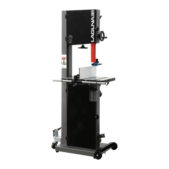
Page 14: Parts Of The Bandsaw
Parts of the Bandsaw. Note: The mobility kit and light are optional. 16 6 12 13 1. Tension indicator window 10. Rip fence assembly 11. Dust port 4” 2. Switch 3. Motor 12. Quick-release blade tension lever 4. Frame 13. Blade tracking knob 5. - Page 15 1. Tension indicator / window. Tension indicators are designed to indicate the compression of a Emergency stop spring. As a rule, the greater the spring compression, the greater button the tension on the blade. The tension scale does not register until the blade is relatively taut and is located on the inside of the body of the bandsaw.
- Page 16 8. Blade guide adjustment hand wheel. The upper blade guides are attached to the blade guide shaft. The shaft is vertically adjustable with a hand wheel. The guides should be adjusted so the guides are just above the wood being cut. This gives the blade maximum stability and is also the safest way to operate the bandsaw.
- Page 17 14. Optional mobility kit. Swivel wheel assembly The optional mobility kit is fitted to the base of the bandsaw and consists of two fixed wheels at the front of the bandsaw and a swivel wheel at the back of the band saw. The swivel wheel is activated and deactivated with a foot lever.
-
Page 18: Where To Locate Your Machine
20. Blade tilt and tension mechanism. The upper wheel is attached to the tilt and tension mechanism. This mechanism adjusts the wheel so that the bandsaw blade can be adjusted for blade tracking. This is achieved by a screwed handle at the back of the machine that pushes on the mechanism and adjusts the axis of the wheel so that it runs true with the lower wheel. -
Page 19: Assembly And Setup
SPRING AND COULD CAUSE INJURY. Your bandsaw will be shipped in custom packaging consisting of a heavy-duty cardboard box and Styrofoam internal packaging. 1. Open the cardboard box and remove the loose parts and top Styrofoam. 2. Lift the bandsaw out of the packaging. You will need two or more people, as the bandsaw is heavy. - Page 20 1. Support the bandsaw on wooden blocks. 2. Fit the swivel assembly to the back of the bandsaw with the provided bolts. 3. Fit the front wheels to the front of the bandsaw with the bolts provided and remove the two rubber feet that are close to the front wheels..
- Page 21 Tilt blanking disc Table tilt hole Tilt stop bolt Tilt blanking disc The table has a reference stop bolt that is used to quickly align the table after tilting. The stop bolt hits the tilt-blanking disc when it is positioned over the table tilt hole. When the tilt blanking disc is moved away from the hole, it allows the tilt stop bolt to pass through the table tilt hole, and the table can be moved to the maximum amount of tilt (-7 degrees).
- Page 22 Trunion clamp stud Ratchet handle With the table fitted to the trunions, assemble the two ratchet handles and flat washers. How to adjust the table for square to the blade. This will be detailed later in the manual. Fitting the table rule. Table rule with fixings Table with rule mounted Attach the rule to the table with the fixings supplied.
- Page 23 Fitting the fence. 1. Fit the fence bar to the table with the screws and spacers supplied. Note. The distance between the fixing holes and the end of the bar is not symmetrical, and the end that has the longest distance must be at the back of the bandsaw (closest to the column).
- Page 24 Allen key Support Allen screw Fence in high position The fence support and the fence are held off the table with a nylon-support Allen screw. This screw ensures that the fence and the fence support do not damage the table. The screw is adjustable to compensate for wear.
- Page 25 Fitting the optional light. Fixing screws and cable clips Light fitted in position Suggested cable route Light plugged into socket The light is fitted to the top of the bandsaw as shown. The light is supplied with a three-pin plug to suit either 110V or 220V depending on your machine votlage. The cable must be held in position with the clips provided and positioned so that the cable is safe and will not in any way come close to the blade or cabinet door.
- Page 26 Connecting the bandsaw to the electricity supply. 110V Electrical plug and cable 220V Electrical plug and Cable Emergency stop The bandsaw is supplied pre-wired with a 110V 3-pin plug or 220V button 3-pin plug. It is recommended that the bandsaw be connected to a 15 amp breaker.
- Page 27 Before starting the bandsaw. Read and understand the instruction manual before operating the saw. 1. If you are still not thoroughly familiar with the operation of the bandsaw, get advice from a qualified person. 2. Make sure the machine is properly grounded and that the wiring codes are followed. 3.
- Page 28 Fitting a blade to the bandsaw. A lot of people do not like to change the blades and go to great lengths to avoid doing it. To use the bandsaw to its greatest advantage, you will have to use the appropriate blade and track it quickly.
- Page 29 8. Open the blade guard door. Slide the blade over the top flywheel and feed through the slot at the side of the vertical column. Then feed the blade into the blade guard slot and close the blade guard door. 9.
- Page 30 Note. Tensioning the blade is covered later in the manual. 2. Refit the plastic blanking block. Note: The blade must be fully tensioned for final tracking. Note: Never track the blade with the saw running. Note. There is a window on the side of the bandsaw that Blade tension wheel allows the blade on the upper flywheel to be viewed.
- Page 31 This can allow the blade to twist as pressure from the wood being cut pushes against the back blade guide. The Laguna Guide eliminates this by...
- Page 32 Laguna guide system. As with the roller guide systems, the Laguna guide system will damage your blade if it is not adjusted correctly. The guide blocks must not come in contact with the teeth of the blade. It is...
- Page 33 Side guide clamp screw Adjusting the blade guides. The blade should run through the center of the rear blade guide, and the side guides should be parallel with the blade. If they have been moved out adjustment, adjust as follows: Top Upper Side Guides Parallel Adjustment.
-
Page 34: Safety Rules
Lower blade guide. Guide locking screws The lower blade guides have two locking screws that, when released, allow the guide assembly to be moved forward and back. Rotate the blade by hand and ensure that it is tracking consistently in the correct position. Loosen the side guides and move out from the blade. - Page 35 This can be overcome to a great degree by using the Resaw king blade from Laguna. The blade has many of advantages such as superior surface finish to the cut, thin kerf (low wood waste), it can be re-sharpened, will cut hard woods and has a long life.
- Page 36 is the angle of drift, and you will have to set the fence to the pencil line. 4. To adjust the fence, loosen the clamp bolts that attach it to the cast bracket. Move the fence so that it lines up with the pencil mark on the table and retighten the clamp screws. Method 2.
- Page 37 Table rule Adjustment slot Fence position. Fence in low position Fence in high position The aluminum fence can be used in two height positions (high and low). The low position is handy for cutting thin wood and is used where the fence in the high position would make it awkward to complete cuts.
- Page 38 Resawing. Resawing is the process of cutting a board in half along its height. The bandsaw is perhaps the most creative tool in the shop because of its ability to cut thick or thin, straight or curved. The ability to cut thick stock such as re-sawing, making veneers, book matching or cutting flitches from small logs has great appeal to the woodworker.
- Page 39 advantage if you are cutting a job that has a tendency to nip the blade. The smaller the set, the smaller the saw cut and the larger the radius that can be cut; the wood waste is less. On tipped blades (Resaw King) there is no set, as the tip is wider than the backing material. Thickness.
- Page 40 Width. The dimension from the back of the blade to the front of the teeth. The wider the blade, the stiffer the blade and the straighter the cut. This is usually called beam strength. But wide blades cannot cut small radiuses. The narrower the blade, the more flexible the blade and the greater the tendency the blade has to wander.
- Page 41 With most guide systems it is recommended that the back of the blade be rounded with a stone. As the machine is supplied with Laguna ceramic guides, this is not imperative because the ceramic will round the back of the blade as it is used. However, if you decide that you want to round the back of the blade, a procedure follows.
- Page 42 4. After use it is recommended that you slacken the tension, especially overnight. (Be sure to place a clearly visible note on the machine that you have done this. 5. Misalignment of the flywheels. 6. Irregularity of flywheel surface, for instance, an accumulation of sawdust while cutting resinous materials.
- Page 43 would work for a particular curve, place a dime (roughly 5/8") over the pattern. The 3/16" blade can cut a curve bigger than the dime, but not smaller. You can use everyday items such as coins or a pencil to determine which blade to use. A quarter is the size of the tightest cut that can be made with a 1/4"...
- Page 44 Step 1 Step 2 Done Step 3 Note: In order to show the hand/thumb position of the man in the photographs, he is not wearing gloves, but gloves MUST BE WORN as the blade could cause injury.
- Page 45 Method Two. There is another variation of this that works well with small blades but simply is not possible for larger bandsaw blades, unless you're very big and strong. This method works the same as the method above, but rather than holding the blade with both hands, grasp the blade at the top while holding the bottom of the blade with your foot (teeth still facing away from you).
- Page 46 Method Three. The steering wheel method. Start with the blade in front of you, as if you're holding a steering wheel with your hands at the 9 o'clock and 3 o'clock positions. Simultaneously twist your left hand up and your right hand down. As the blade starts to fold, move your hands closer together while tilting your left hand to the right and your right hand to the left.
-
Page 47: Maintenance
Maintenance. All tools and machines require regular maintenance, and the bandsaw is no exception. This section details the general maintenance and care of your bandsaw. In general, we recommend that you only use a Teflon-based lubricant on the bandsaw. While regular oil attracts dust and dirt, Teflon tends to dry and has fewer tendencies to accumulate dirt and sawdust on your machine. - Page 48 Replacing the drive belt. Drive belt adjusting bolt Motor drive pulley Drive belt Flywheel shaft nut To replace the belts you will have to remove the lower flywheel. 1. Loosen the motor clamp bolts and move the motor so that the tension is completely removed from the drive belt.
- Page 49 Rust. The bandsaw is made from steel and cast iron. All non-painted surfaces will rust if not protected. It is recommended that the table be protected by coating with wax if the machine is not in constant use. All moving non-painted surfaces (guides, rack and pinion, etc.) should be lubricated/protected with a Teflon-based lubricant.
- Page 50 Adjusting the table square to the bandsaw blade. Note. The machine is set in the factory and no adjustment should be required but during transportation movement may occur. To access the adjustment screws, you will have to tilt the table up to 45 degrees and lock in position.
-
Page 51: Troubleshooting
bolt to pass through the table tilt hole, and the table can be moved to the maximum amount of tilt (-7 degrees). To adjust the table square to the blade. 1. Check that the stop bolt is in contact with the tilt-blanking disc. 2. - Page 52 2. Internal breaker faulty. Replace the breaker. Motor tries to start but will not turn. 1. With the power disconnected from the machine, open the doors and try to turn the wheel by hand. If the wheel is not turning, check the reason for the jamming. Typical reasons are: guides too tight, wood jammed in the wheel.
- Page 53 The blade makes a clicking noise. Bad weld. Dress the weld or change the blade. Blade overheats. 1. Dull blade. Change the blade or resharpen the blade. 2. Pitch is too small for the depth of cut. Change to a blade with the correct pitch. 3.
-
Page 54: Electrical Drawing
LT14BX (MBAND14BX220-0175)220V wiring diagram. -
Page 55: Exploded View Drawings/Parts
LT14BX (MBAND14BX110-0175)110/220V Bandsaw exploded view drawing/parts . Supplier Part Laguna Part Number Number Item Description Specification Upper Wheel Assembly PBAND1412-175-1 1412-101 Hex Nut M14x1.5- LH PBAND1412-175-2 1412-102 Ball Bearing 6202LLU PBAND1412-175-3 1412-103 C-Ring PBAND1412-175-4 1412-104 PU Tire PBAND1412-175-5 1412-105 Upper Wheel... - Page 56 Tracking Window PBAND1412-175-31 1412-131 Screw #10-24×1/2" 1/4”-20 PBAND1412-175-32 1412-132 Hex Nut PBAND1412-175-33 1412-133 Door Stud PBAND1412-175-34 1412-134 Tension Gauge MBAND14BX110-175- 14BX110-175-135 Phillips Flat Head Screw M3x4 MBAND14BX110-175- 14BX110-175-136 ON/ OFF Switch PBAND1412-175-37 1412-137 Screw M5x0.8x16 PBAND1412-175-38 1412-138 Outlet(110V) MBAND14BX220-250- 14BX220-250-138...
- Page 57 PBAND1412-175-45 1412-145 Screw 1/4"-20x3/4" PBAND1412-175-46 1412-146 Lock Knob MBAND14BX110-175- 14BX110-175-147 Saw Body PBAND1412-175-48 1412-148 Lock Knob PBAND1412-175-49 1412-149 Adjusting Knob PBAND1412-175-50 1412-150 Tension Label PBAND1412-175-51 1412-151 Upper Door MBAND14BX110-175- 14BX110-175-152 Logo Label PBAND1412-175-53 1412-153 Hinge Cover MBAND14BX110-175- 14BX110-175-154 Emergency Stop...
- Page 59 Supplier Part Laguna Part Number Number Item Description Specification Lower Wheel and Motor Assembly PBAND1412-175-2-1 1412-101 Hex Nut M14x1.5- LH PBAND1412-175-2-2 1412-102 Ball Bearing 6202LLU PBAND1412-175-2-3 1412-103 C-Ring PBAND1412-175-2-4 1412-104 PU Tire PBAND1412-175-2-5 1412-105 Upper Wheel PBAND1412-175-2-6 1412-206 Poly-V Belt...
- Page 60 Lock Knob PBAND1412-175-2-35 1412-145 Screw 1/4"-20x3/4" PBAND1412-175-2-36 1412-236 Plate PBAND1412-175-2-37 1412-237 Screw #10-24×3/8" PBAND1412-175-2-38 1412-238 Strain Relief 6N-4 MBAND14BX110-175-2- 14BX110-175-239 Motor Cord MBAND14BX110-175-2- 14BX110-175-240 Power Cord(110V) MBAND14BX220-250-2- 14BX220-250-240 Power Cord(220V) PBAND1412-175-2-41 1412-241 Hex Cap Screw 3/8"-16x1" PBAND1412-175-2-42 1412-242 Flat Washer 3/8"...
- Page 61 MBAND14BX110-175-2- 14BX110-175-252 Limited Switch Cord MBAND14BX110-175-2- 1412-112 Flat Washer 3/8" MBAND14BX110-175-2- 14BX110-175-254 Set Screw M6x1.0x45 MBAND14BX110-175-2- 1412-336 Hex Nut 3/8"-16 MBAND14BX110-175-2- 14BX110-175-256 Foot Brake MBAND14BX110-175-2- 5/16- 14BX110-175-257 Socket Head Cap Screw 18UNCx1/2 MBAND14BX110-175-2- 3/8-16UNCx1- 14BX110-175-258 Hex Cap Screw 1/4" MBAND14BX110-175-2-...
- Page 63 Supplier Part Laguna Part Number Number Item Description Specification Table and Fence Assembly PBAND1412-175-3-1 1412-301 Aluminum Fence PBAND1412-175-3-2 1412-302 Plastic Adjusting Screw PBAND1412-175-3-3 1412-303 Fence Body PBAND1412-175-3-4 1412-304 Lock Knob PBAND1412-175-3-5 1412-305 Socket Head Cap Screw 5/16"-18x3/4" PBAND1412-175-3-6 1412-213 Lock Washer 5/16"...
- Page 64 PBAND1412-175-3-33 1412-333 Set Screw 5/16"-18x5/8" PBAND1412-175-3-34 1412-334 Hex Cap Screw 5/16"-18x1-3/4" PBAND1412-175-3-35 1412-335 Hex Cap Screw 3/8"-16×2" PBAND1412-175-3-36 1412-336 Hex Nut 3/8"-16 PBAND1412-175-3-37 1412-337 Phillips Flat Head Screw M4x0.7x8 PBAND1412-175-3-38 1412-338 Hex Nut 5/16"-18 PBAND1412-175-3-39 1412-211 Flat Washer 5/16" PBAND1412-175-3-40 1412-340 Lock Handle PBAND1412-175-3-41...
- Page 66 Supplier Part Laguna Part Number Number Item Description Specification Upper and Lower Blade Guides Assembly PBAND1412-175-4-1 1412-401 Lock Knob PBAND1412-175-4-2 1412-208 Set Screw 5/16"-18x3/8" PBAND1412-175-4-3 1412-143 Set Screw 1/4"-20x3/8" PBAND1412-175-4-4 1412-404 Hand Wheel PBAND1412-175-4-5 1412-405 Handle PBAND1412-175-4-6 1412-406 Pointer PBAND1412-175-4-7...
- Page 67 PBAND1412-175-4-33 1412-433 Lock Handle PBAND1412-175-4-34 1412-434 Support Shaft PBAND1412-175-4-35 1412-435 Lock Knob PBAND1412-175-4-36 1412-436 Socket Head Button Screw 1/4"-20x1/2" PBAND1412-175-4-37 1412-437 Base PBAND1412-175-4-38 1412-438 Special Bolt PBAND1412-175-4-39 1412-211 Flat Washer 5/16" PBAND1412-175-4-40 1412-440 Hex Cap Screw 5/16"-18x1" PBAND1412-175-4-41 1412-213 Lock Washer 5/16"...
- Page 68 Laguna Part Number Supplier Part Number Item Description Specification Mobility System: Optional PBAND1412-175-6-1 1412-601 PBAND1412-175-6-2 1412-232 Flat Washer 1/4" 1/4"-20x1- PBAND1412-175-6-3 1412-603 Socket Head Cap Screw 3/4" PBAND1412-175-6-4 1412-421 Socket Head Button Screw 5/16"-18x1/2" PBAND1412-175-6-5 1412-605 Flat Washer 5/16" PBAND1412-175-6-6...
- Page 69 PBAND1412-175-6-15 1412-615 Connecting Plate PBAND1412-175-6-16 1412-616 Foot Pedal PBAND1412-175-6-17 1412-617 Socket Head Button Screw 1/4"-20x3/8" PBAND1412-175-6-18 1412-618 Plate PBAND1412-175-6-19 1412-619 Spacer PBAND1412-175-6-20 1412-620 Support Plate PBAND1412-175-6-21 1412-621 Support Plate PBAND1412-175-6-22 1412-622 PBAND1412-175-6-23 1412-623 Wheel PBAND1412-175-6-24 1412-624 Retaining Pin PBAND1412-175-6-25 1412-125.4 Nylon Inserted Lock Nut M5x0.8 PBAND1412-175-6-26...
- Page 70 Supplier Part Laguna Part Number Number Item Description Specification 115V Industrial Work Light: Optional PBAND1412-175-7-1 1412-701 Work Light 115V PBAND1412-175-7-2 1412-702 Screw M4x0.7x20 PBAND1412-175-7-3 1412-703 Flat Washer PBAND1412-175-7-4 1412-704 Hex Nut M4x0.7 PBAND1412-175-7-5 1412-705 Cable Clamp...
- Page 71 Supplier Part Laguna Part Number Number Item Description Specification 230V Industrial Work Light: Optional PBAND14BX220-250-7-1 14BX220-250-701 Work Light 230V PBAND1412-175-7-2 1412-702 Screw M4x0.7x20 PBAND1412-175-7-3 1412-703 Flat Washer PBAND1412-175-7-4 1412-704 Hex Nut M4x0.7 PBAND1412-175-7-5 1412-705 Cable Clamp...
- Page 72 Laguna Tools is not responsible for errors or omissions. Specifications subject to change. Machines may be shown with optional accessories. © 2017, Laguna Tools, Inc. LAGUNA® and the LAGUNA Logo® are the registered trademarks of Laguna Tools, Inc. All rights reserved.
Need help?
Do you have a question about the MBAND14BX110-175 and is the answer not in the manual?
Questions and answers