
Related Manuals for laguna 14-Twelve Bandsaw


Summary of Contents for laguna 14-Twelve Bandsaw
- Page 1 14-Twelve Bandsaw Manual LAGUNA TOOLS 17101 Murphy Ave. Irvine, California 92614 Part No. MBAND1412-175 Ph: 800.234.1976 © 2013 Laguna Tools, Inc. All rights reserved. www.lagunatools.com...
- Page 2 Dear Woodworker, Thank you for your purchase and welcome to the Laguna Tools group of discriminating woodworkers. I understand that you have a choice of where to purchase your machines and appreciate the confidence you have in our products. Every machine sold by Laguna Tools has been carefully designed and well thought through from a woodworker’s perspective.
-
Page 3: Safety Rules
WARNING: For your own safety, read instruction manual before operating bandsaw Wear eye protection. Do not remove jammed cut off pieces until blade has stopped. Maintain proper adjustment of blade tension, blade guides and thrust bearings. Adjust upper guide to just clear workpiece. Hold workpiece firmly against table. - Page 4 11. ALWAYS USE SAFETY GLASSES. Also use face or dust mask if cutting operation is dusty. Everyday eyeglasses only have impact-resistant lenses; they are NOT safety glasses. 12. SECURE WORK. Use clamps or a vise to hold work when practical. It's safer than using your hand, and it frees both hands to operate tool.
- Page 5 Grounding Instructions 1. All grounded, cord-connected tools: In the event of a malfunction or breakdown, grounding provides a path of least resistance for electric current to reduce the risk of electric shock. This tool is equipped with an electric cord having an equipment-grounding conductor and a grounding plug.
- Page 6 3. Grounded, cord-connected tools intended for use on a supply circuit having a nominal rating of 150–250 volts, inclusive: This tool is intended for use on a circuit that has an outlet that looks like the one illustrated in Sketch D. The tool has a grounding plug that looks like the plug illustrated in Sketch D.
-
Page 7: Table Of Contents
Table of Contents Page number Safety Rules Warranty Noise emission Specification sheet Receiving your machine Introduction to your machine Parts of the bandsaw Where to locate your machine Unpacking your machine Assembly and set up Testing the bandsaw Using the bandsaw Maintenance and troubleshooting Electrical drawing Exploded view drawings and parts list... -
Page 8: Warranty
Inc., to be a manufacturer's defect. We require the defective item/part to be returned to Laguna Tools. In the event the item/part is determined to be damaged due to lack of maintenance, cleaning or misuse/abuse, the customer will be responsible for the cost to replace the item/part, plus all related shipping charges. -
Page 9: Noise Emission
116" (2,946mm) Maximum blade width 3/4" (19mm) Minimum blade width 1/8" (3mm) Guides Laguna ceramic Height 70 1/4" (1,784mm) Machine Dimensions (W x D) 31 1/2" x 26 7/8" (800mm x 683mm) Stand Footprint 25 1/4" x 18 1/8" (642mm x 460mm) Machine Dimensions with 34 3/4"... -
Page 10: Receiving Your Machine
Receiving Your Machine It is probable that your machine will be delivered by a third party. Before you unpack your new machine, you will need to first inspect the packing, invoice and shipping documents supplied by the driver. Ensure that there is no visible damage to the packing or the machine. You need to do this prior to the driver leaving. - Page 11 continuous sawing action. Because the direction of the blade is always downward toward the table, there is little danger (except for special cuts) that the wood will be thrown back at the operator, which is called a kickback. There is always danger of kickback when a circular saw is being used.
- Page 12 Fence guide bar Fence parts and hand wheel Table ratchet handles Fence lock knob Feet & screws T-handle Fence bar parts and fixings Table Fixings Note: The mobility kit and light are optional...
-
Page 13: Parts Of The Bandsaw
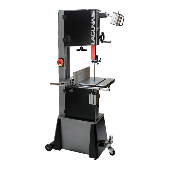
Parts of the Bandsaw 1. Tension indicator window 10. Rip fence assembly 2. Switch 11. Dust port 4” 3. Motor 12. Quick-release blade tension lever 4. Frame 13. Blade tracking knob 5. Blade tension handle 14. Optional mobility kit 6. Blade tracking window 15. - Page 14 1. Tension indicator/window Tension indicators are designed to indicate the compression of a spring. As a rule, the greater the spring compression, the greater the tension on the blade. The tension scale does not register until the blade is relatively taut and is located on the inside of the body of the bandsaw.
- Page 15 8. Blade guide adjustment hand wheel The upper blade guides are attached to the blade guide shaft. The shaft is vertically adjustable with a hand wheel. The guides should be adjusted so the guides are just above the wood being cut. This gives the blade maximum stability and is also the safest way to operate the bandsaw.
- Page 16 14. Optional mobility kit The optional mobility kit is fitted to the stand and consists of two fixed wheels at the back of the bandsaw and a swiveling wheel at the front of the band saw. The swivel wheel is activated and deactivated with a foot lever. With the swivel wheel deactivated, the bandsaw sits on two feet.
-
Page 17: Unpacking Your Machine
rotated, will move the wheel up or down. The machine has a quick-acting blade release mechanism that is located at the back of the machine and will remove the tension from the blade to speed the removal and fitting of blades. The mechanism has a spring, which helps to keep the tension constant as the blade expands and contracts with the heat generated by the cutting action. -
Page 18: Assembly And Set Up
2. Lift the bandsaw out of the packaging. You will need two or more people, as the bandsaw is heavy. 3. Lift the bottom Styrofoam out and remove the parts that are packaged under the bandsaw and packaging. Assembly and Set Up Assembling the bandsaw stand Fixing bolts Stand viewed from inside... - Page 19 Assembling the mobility kit to the stand Optional mobility kit Support bracket fixing screw Mobility front wheel screwed onto the shaft Front mobility wheel with spring fitted The mobility kit consists of a front swivel wheel and two wheels at the back of the bandsaw.
- Page 20 2. Fit the front swivel wheel on the stand as shown by bolting in position through the stand onto the support bracket. Do not fully tighten the screws, as the height of the wheel will have to be adjusted to suit the stand. 3.
- Page 21 Fitting the stand to the bandsaw (shown with opitional mobility kit). Motor supported Bandsaw raised off the ground You will probably find that it is easier to fit the stand to the bandsaw with it in the horizontal position and then lifting it to the vertical position as shown in the above photographs.
- Page 22 that you feel is unsafe or that you do not have the physical capability of achieving, as the bandsaw is heavy. You will probably find it easier to assemble the stand to the bandsaw prior to fitting the other part (table, etc.), as it is lighter. With the stand aligned to the bandsaw, fit the fixing screws and fully tighten.
- Page 23 Table mounted to the bandsaw Trunion clamp stud Ratchet handle Allen key With the table fitted to the trunions, assemble the two ratchet handles. Adjusting the table for square to the blade is covered latter in the manual. Fitting the guide vertical shaft adjustment handle Loosen the clamping screw so that the handle can slide on the shaft.
- Page 24 Fitting the table rule Table rule with fixings Table with rule mounted Attach the rule to the table with the fixings supplied. Do not fully tighten the bolts, as the position of the rule will have to be adjusted to suit the blade, which will be detailed latter in the manual.
- Page 25 1. Fit the fence bar to the table with the screws and spacers suppliers. Note. The distance between the fixing holes and the end of the bar is different, and the end that has the longest distance must be at the back of the bandsaw (closest to the column).
-
Page 26: Testing The Bandsaw
Fitting the optional light Fixing screws and cable clips Light fitted in position Suggested cable route Light plugged into 110v socket The light is fitted to the top of the bandsaw as shown. The light is supplied with a 110-volt three-pin plug. The cable must be held in position with the clips provided and positioned so that the cable is safe and will not in any way come close to the blade or cabinet door. - Page 27 5. Wear a dust mask; long-term exposure to the fine dust created by the bandsaw is not healthy. 6. Remove your tie, rings, watch and all jewelry. Roll up your sleeves; you do not want anything to get caught in the saw. 7.
- Page 28 3. Check that the machine is clear of all tools and other loose objects. 4. Check that all the adjusting and locking handles are tight. 5. Check that there is no blade fitted; it is far safer to test the machine without a blade fitted.
- Page 29 Fitting a blade to the bandsaw A lot of people do not like to change the blades and go to great lengths to avoid doing it. To use the bandsaw to its greatest advantage, you will have to use the appropriate blade and track it quickly.
- Page 30 9. Deactivate the quick action blade tension lever and rotate the blade tension wheel so that the blade can fit over the lower flywheel. 10. Activate the quick action blade tension lever. Lock knob 11. Apply light tension to the blade with the blade tension wheel.
- Page 31 1. To track the blade start rotating the wheels by hand in the normal direction. As you do this, watch the blade to determine where the blade wants to track. If the blade is tracking too far forward or backward, make small adjustments with the tracking adjustment knob located at the back of the bandsaw while still rotating the wheel.
- Page 32 Plug the machine into the power. Turn the machine on for a second and switch off. Watch how the blade runs. If the blade tracks well, then run the machine at full power. If the blade tracking needs adjustment, repeat adjustment. Method 2 Tension the blade as described in method 1.
- Page 33 Please read the following notes, as they will assist you in getting the optimum performance from your Laguna guide system. As with the roller guide systems, the Laguna guide system will damage your blade if it is not adjusted correctly. The guide blocks must not come in contact with the teeth of the blade.
- Page 34 7. The side guide blocks must be tightened before running the machine to avoid jamming the blade and damaging the machine and/or guide blocks. 8. When cutting gummy or green wood, the blade can become covered with resin. You will find that the surround guide system ceramic blocks remove the resin as the blade is moved through the guide blocks and keep that part of the blade clean.
- Page 35 guide to obtain the correct clearance until you gain experience. Tighten the clamp screws and remove the paper. Rotate the blade by hand, ensuring that the weld of the blade does not hit the ceramic blocks, as this will cause damage. If the blade has a bad weld, dress the blade or return it to your supplier.
-
Page 36: Using The Bandsaw
This can be overcome to a great degree by using the Resaw king blade from Laguna. The blade has many of advantages such as superior surface finish to the cut, thin kerf (low wood waste), can be re-sharpened, will cut hard woods and has a long life. - Page 37 Adjusting the fence Method1 1. Make a straight pencil line on the edge of a board. 2. Feed the wood into the blade cutting next to the pencil mark. If the blade is drifting, you will have to compensate by angling the wood to keep the cut straight.
- Page 38 Adjusting the table rule Table rule Adjustment slot There is a rule that is fitted to the side of the table and can be used as a quick guide on the distance that the fence is from the blade. Note. The rule will have to be adjusted each time the fence is adjusted for drift, as this will change the distance the fence is from the blade.
- Page 39 Changing the fence height 1. Loosen the clamp screws that are located on the cast bracket. 2. Slide the aluminum fence off the cast iron bracket. 3. Slide the aluminum fence back onto the bracket using the second slot and retighten the clamp screws.
- Page 40 Thickness The thicker the blade, the stiffer the blade and the straighter the cut. The thicker the band, the greater the tendency for the blade to break. Pitch The size of the teeth. This is usually quoted in teeth per inch (TPI). The larger the tooth, the faster the cut because the tooth has a large gullet and has a greater capacity to transport large amounts of sawdust through the job.
- Page 41 Width The dimension from the back of the blade to the front of the teeth. The wider the blade, the stiffer the blade and the straighter the cut. This is usually called beam strength. But wide blades cannot cut small radiuses. The narrower the blade, the more flexible the blade and the greater the tendency the blade has to wander.
- Page 42 With most guide systems it is recommended that the back of the blade be rounded with a stone. As the machine is supplied with Laguna ceramic guides, this is not imperative because the ceramic will round the back of the blade as it is used.
- Page 43 Causes of Blade Breakage 1. Excessive blade thickness in relation to the flywheel diameter. 2. Defective welding. 3. Incorrect tension, particularly if the blade is over tensioned; the tension spring no longer fulfills its function. 4. After use it is recommended that you slacken the tension, especially overnight (placing a visible notice of this operation).
- Page 44 without backtracking any curve that has a radius as much as or more than is shown on the chart. For example: a 3/16" blade will cut a circle with a 5/16" radius or a 5/8" diameter. To test if a 3/16" blade would work for a particular curve, place a dime (roughly 5/8") over the pattern.
- Page 45 How to coil a bandsaw blade Without a doubt it is more difficult to explain how to coil a bandsaw blade than it is to actually do it. Nevertheless, below are easy-to-follow instructions on folding a blade. Method One While wearing a jacket or long-sleeved shirt and gloves, hold the blade in front of you in one large loop, with the teeth facing towards you.
- Page 46 Method Two There is another variation of this that works well with small blades but simply is not possible for larger bandsaw blades, unless you're very big and strong. This method works the same as the method above, but rather than holding the blade with both hands, grasp the blade at the top while holding the bottom of the blade with your foot (teeth still facing away from you).
- Page 47 Method Three The steering wheel method. Start with the blade in front of you, as if you're holding a steering wheel with your hands at the 9 o'clock and 3 o'clock positions. Simultaneously twist your left hand up and your right hand down. As the blade starts to fold, move your hands closer together while tilting your left hand to the right and your right hand to the left.
-
Page 48: Maintenance And Troubleshooting
Maintenance and Troubleshooting All tools and machines require regular maintenance, and the bandsaw is no exception. This section details the general maintenance and care of your bandsaw. In general, we recommend that you only use a Teflon- based lubricant on the bandsaw. Regular oil attracts dust and dirt, and the Teflon tends to dry and has fewer tendencies to accumulate dirt and sawdust on your machine. - Page 49 Replacing the drive belt Drive belt adjusting bolt Motor drive pulley Drive belt Flywheel shaft nut To replace the belts you will have to remove the lower flywheel. Loosen the motor clamp bolts and move the motor so that the tension is completely removed from the drive belt.
- Page 50 Bearings All bearings are sealed for life and do not require any maintenance. If a bearing becomes faulty, replace it. Rust The bandsaw is made from steel and cast iron. All non-painted surfaces will rust if not protected. It is recommended that the table be protected by coating with wax if the machine is not in constant use.
- Page 51 machine will not stop. The machine will not stop This is a very rare occurrence, as the machine is designed to be fail-safe. If it should occur and you cannot fix the fault, seek professional assistance. The machine must be disconnected from the power and never run until the fault has been rectified.
- Page 52 The blade makes a clicking noise Bad weld. Dress the weld or change the blade. Blade overheats 1. Dull blade. Change the blade or resharpen the blade. 2. Pitch is too small for the depth of cut. Change to a blade with the correct pitch. 3.
-
Page 53: Electrical Drawing
Electrical Drawing... -
Page 54: Exploded View Drawings And Parts List
Exploded View Drawings and Parts List Industrial Work Light: Optional... - Page 55 Lower Wheel And Motor Assembly...
- Page 56 Stand Assembly...
- Page 57 Table and Fence Assembly...
- Page 58 Upper and Lower Blade Guides Assembly...
- Page 59 Upper Wheel Assembly...
- Page 60 Wheel System: Optional...
- Page 61 LT14-12 [MBAND1412-175] 110 VOLT BANDSAW Supplier Laguna part No part Item description Specification Qty number Upper Wheel Assembly PBAND1412-175-1 1412-101 Hex Nut M14x1.5- LH PBAND1412-175-2 1412-102 Ball Bearing 6202LLU PBAND1412-175-3 1412-103 C-Ring PBAND1412-175-4 1412-104 PU Tire PBAND1412-175-5 1412-105 Upper Wheel...
- Page 62 PBAND1412-175-26 1412-126 Screw M4x0.7x8 PBAND1412-175-27 1412-127 Hex Nut #10-24 PBAND1412-175-28 1412-128 Lock Washer PBAND1412-175-29 1412-129 Flat Washer PBAND1412-175-30 1412-130 Tracking Window PBAND1412-175-31 1412-131 Screw #10-24×1/2" PBAND1412-175-32 1412-132 Hex Nut 1/4”-20 PBAND1412-175-33 1412-133 Door Stud PBAND1412-175-34 1412-134 Tension Gauge PBAND1412-175-35 1412-135 Screw M3x0.5x15 PBAND1412-175-36...
- Page 63 PBAND1412-175-2-11 1412-211 Flat Washer 5/16" PBAND1412-175-2-12 1412-212 Spindle Pulley PBAND1412-175-2-13 1412-213 Lock Washer 5/16" 5/16"-18x1- PBAND1412-175-2-14 1412-214 Socket Head Cap Screw 1/2" PBAND1412-175-2-15 1412-215 Lower Spindle PBAND1412-175-2-16 1412-216 Hex Cap Screw M5x0.8x30 PBAND1412-175-2-17 1412-129 Flat Washer PBAND1412-175-2-18 1412-218 Brush PBAND1412-175-2-19 1412-140 Hex Nut M5x0.8...
- Page 64 PBAND1412-175-2-43 1412-108 Lock Washer 3/8" PBAND1412-175-2-44 1412-244 Hex Nut M14x1.5 PBAND1412-175-2-45 1412-245 Motor 1412- 245MF Motor Fan (not shown) 1412- Motor Fan Cover (not 245MFC shown) 1412- Junction Box (not 245JB shown) 1412- Junction Box Cover (not 245JBC shown) PBAND1412-175-2-46 1412-246 Spindle Holder PBAND1412-175-2-47...
- Page 65 PBAND1412-175-3-25 1412-142 Lock Washer 1/4" PBAND1412-175-3-26 1412-326 Socket Head Cap Screw M6x1.0x16 PBAND1412-175-3-27 1412-327 Pointer PBAND1412-175-3-28 1412-328 Screw M5x0.8x8 PBAND1412-175-3-29 1412-329 Bracket PBAND1412-175-3-30 1412-242 Flat Washer 3/8" PBAND1412-175-3-31 1412-331 Lock Handle 5/16”-18x1- PBAND1412-175-3-32 1412-332 Hex Cap Screw 1/4" PBAND1412-175-3-33 1412-333 Set Screw 5/16"-18x5/8"...
- Page 66 Socket Head Button PBAND1412-175-4-21 1412-421 Screw 5/16"-18x1/2" PBAND1412-175-4-22 1412-422 Guide Bar PBAND1412-175-4-23 1412-423 Socket Head Cap Screw 1/4”-20x5/8” PBAND1412-175-4-24 1412-142 Lock Washer 1/4" PBAND1412-175-4-25 1412-425 Lock Knob PBAND1412-175-4-26 1412-426 Ceramic Guide PBAND1412-175-4-27 1412-427 Adjusting Block PBAND1412-175-4-28 1412-428 Fixed Block PBAND1412-175-4-29 1412-429 Lock Knob PBAND1412-175-4-30...
- Page 67 PBAND1412-175-6-7 1412-607 Fixed Plate PBAND1412-175-6-8 1412-608 Wheel Bracket PBAND1412-175-6-9 1412-609 DU Bearing MB1620DU PBAND1412-175-6-10 1412-610 Spring PBAND1412-175-6-11 1412-611 Caster PBAND1412-175-6-12 1412-612 Spacer PBAND1412-175-6-13 1412-613 Flat Washer PBAND1412-175-6-14 1412-614 Screw M5x0.8x20 PBAND1412-175-6-15 1412-615 Connecting Plate PBAND1412-175-6-16 1412-616 Foot Pedal Socket Head Button PBAND1412-175-6-17 1412-617 Screw...
- Page 68 LAGUNA TOOLS 17101 Murphy Ave. Irvine, California 92614 Ph: 800.234.1976 www.lagunatools.com © 2013 Laguna Tools, Inc. All rights reserved.
Need help?
Do you have a question about the 14-Twelve Bandsaw and is the answer not in the manual?
Questions and answers