Table of Contents

Subscribe to Our Youtube Channel
Related Manuals for laguna MTSAW17536110-0130


Summary of Contents for laguna MTSAW17536110-0130
- Page 1 Fusion Tablesaw Manual Model MTSAW17536110-0130 Model MTSAW17536110-0130 Model MTSAW17536110-0130 LAGUNA TOOLS 2072 Alton Parkway Irvine, California 92606 Ph: 800.234.1976 © 2015 Laguna Tools, Inc. All rights reserved. www.lagunatools.com...
-
Page 2: Table Of Contents
Table of contents READ CAREFULLY BEFORE OPERATING THE MACHINE .............2 10” TABLE SAW .........................4 GROUNDING INSTRUCTIONS ....................5 MOVEABLE CASTER & MACHINE LEVELING ................6 RESET PROTECTOR.........................6 SAFETY SWITCH ........................7 UNPACKING ..........................7 CLEAR UP ..........................7 PLACEMENT OF THE TABLW SAW ..................7 ASSEMBLY OF THE TABLE SAW .....................8 INSTALL BLADE GUARD ......................10 RIVING KNIFE ..........................11 TABLE INSERT ........................12... -
Page 3: Read Carefully Before Operating The Machine
READ CAREFULLY BEFORE OPERATING THE MACHINE Read this manual completely and observe all warning labels on the machine. We always make every attempt to provide a safe, reliable, easy-to-use piece of machinery. Safety, however, is ultimately the responsibility of the individual machine operator. As with any piece of machinery, the operator must exercise caution, patience, and common sense, to safely operate the machine. - Page 4 17. Avoid working from awkward or off balance positions. Do not overreach while cutting; keep both feet on floor. Never lean over or reach over the blade and never pull the work piece over the blade from behind. 18. Use out feed support or have an assistant help when ripping long material. 19.
-
Page 5: 10" Table Saw
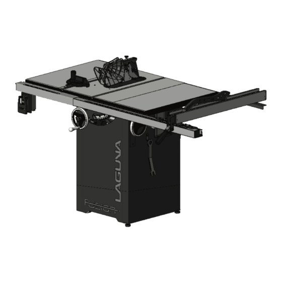
10” TABLE SAW Thank you for choosing this table saw. This unit is carefully tested and inspected before shipment. To ensure optimum performance and trouble free operation a reasonable amount of care and attention is required. To get the most from your new table saw, please take the time to read this manual before assembling, installing and operating the unit. -
Page 6: Grounding Instructions
GROUNDING INSTRUCTIONS 3. Grounded, cord-connected tools intended for use on a supply circuit having a nominal rating 1. All grounded, cord connected tools: between In the event of a malfunction or breakdown, 150-250 volts, inclusive: grounding provides a path of least resistance This tool is intended for use on a circuit that for electric current to reduce the risk of has an outlet that looks like the one... -
Page 7: Moveable Caster & Machine Leveling
MOVEABLE CASTER & MACHINE LEVELING The machine is supplied with (2) casters with leveling adjustors and (2) adjustable feet. To level the machine adjust the leveling adjustors on the castors using a open wrench and adjust the leveling feet. RESET PROTECTOR Your saw comes equipped with a manual-reset thermal-overload protector. -
Page 8: Safety Switch
SAFETY SWITCH The table saw is equipped with a push-button switch that will accept a safety padlock (not included). See Fig. 1. To safeguard your machine from unauthorized operation and accidental starting by young children, the use of a padlock is required. p: With a screw driver, push a solvent-saturated rag o T-slots to remove the grease. -
Page 9: Assembly Of The Table Saw
ASSEMBLING THE TABLE SAW FRONT RAIL INSTALATION INSTALL THE TABLE EXTENSION WINGS Note: The 36” front rail has 2 pieces of Tubes & a join pin but 52” Rail is single Attach the table extension wings to the piece. main table using 8x12mm hex head bolts (4 per wing), and 8 lock washers. - Page 10 5. From the right side of the saw, slide the RIGTH TABLE OF 52” RAIL INSTALLED upper slot of the right front rail onto the 1. Assemble the right table assembly to the square head bolts (for 36” rail only) extension table and align to the front rail mounting holes.
-
Page 11: Install Blade Guard
FITTING THE START /STOP SWITCH The Switch box assembly slides onto the rail slot and can be adjusted to any position to suit you, but it is suggested that it is close to the end of the aluminum rail. Once in position clamp in position by tightening the nuts. -
Page 12: Riving Knife
LOOSEN LOCK KNOB If you could not loosen the knob by hands, use the arbor wrench. See Fig. 4 ANTI-KICK BACK PAWL The anti-kickback pawls allow the work piece to travel in only one direction. If the work piece moves backwards, the pawls will dig into the Fig. -
Page 13: Saw Blade
TABLE INSERT See Fig. 8 To install the zero clearance insert: 1. Disconnect saw from power! 2. Check to make sure the blade is properly installed. 3. Install the table insert 4. Adjust the table insert set screws with a 2.5mm hex wrench to make sure the insert is flush with the table then turn the lock knob to secure the insert. -
Page 14: Fence Assembly
FENCE ASSEMBLY ALIGN THE FENCE PARALLEL TO THE BLADE 1. Slide the fence to the right T-slot on your saw table top. Lock down the fence handle and make a visual check that the fence is parallel with the T-slot all along its length. - Page 15 LEVEL THE FENCE The fence should be parallel to the table and sit approximately 2mm above the table’s surface (so the fence will not scratch the table and a thin work piece will not get stuck or jammed under the fence). To level and adjust the height of the fence: 1.
-
Page 16: Miter Gauge
PUSH STICK Always use a push stick Fig. 19 to reduce the risk of injury. This will keep your hands away from the blade while cutting. To maintain control when cutting large work pieces, start the cut by feeding by hand then use a push sticks to finish the cut. -
Page 17: Maintenance & Adjustments
MAINTENANCE & ADJUSTMENTS LUBRICATION Keep the blade height screw A (under the PERIODIC MAINTENANCE table on the left side) as well as the blade tilt screw B (under the table on the right side) • Inspect/test the ON/OFF switch before well lubricated and free of dust or debris. - Page 18 ADJUSTING THE 45° & 90° BEVEL STOPS 1. Disconnect the machine from the power source. 2. Raise the blade to its highest position and lift the blade guard. 3. Loosen the bevel lock knob and turn the blade tilting hand wheel clockwise until it stops.
- Page 19 BLADE HEIGHT ADJUSTMENT The blade height adjustment hand wheel A is located on the front of the saw and there is a lock knob B on the hand wheel that allows you to lock the wheel and secure the blade at the desired height Fig.
-
Page 20: Type Of Cut
TYPE OF CUT BEVEL RIPPING RIPPING Bevel ripping is performed the same as ripping Cutting a wood plank or sheet of plywood but with the saw blade set to an angle, not lengthwise to reduce its width is called “ripping”. perpendicular with the table surface. - Page 21 CROSS CUTTING Cutting against the grain, to shorten the length of a board, is crosscutting. With some smaller sized and rectangular pieces, you often have the choice of ripping or crosscutting. Always use the miter gauge, when crosscutting; never cut a piece unsupported. The miter gauge may be used in either slot, but most operators prefer the left groove for typical work.
-
Page 22: Wiring Diagrams
WIRING DIAGRAMS 1.75HP.110/220V.60HZ.1PH... - Page 23 2HP.220V.60HZ.1PH...
-
Page 24: Parts Diagrams
PARTS DIAGRAMS... -
Page 28: Parts List
PARTS LIST Part No. Descriptions Q'ty 923135-000 Rip Fence Assembly 250483-615 End Cap 310100-909 Adaptor 000002-308 Hex. screw M6*1.0P*45 171993-904 Bracket 250602-621 Frictional Plate 048701-101 Square Bolt M8*1.25P*20 250799-620 Pointer 001101-205 Round Head Tapping Screw M3*1.06P*6 000304-210 Pan Head Screw M6*1.0P*6 1.10 173142-308... - Page 29 Part No. Descriptions Q'ty 171154-904 130270-903 Rod Bracket -Left 2.10 130271-903 Rod Bracket -Right 2.11 000302-103 Pan Head Screw M4*0.7P*10 2.12 360960-901 2.13 250818-620 Right Cover 2.14 250819-620 Protective Shield -Right 2.15 008302-100 Anti-loose Nut M5*0.8P 2.16 171378-904 Anti-Kick Finger -Left 2.17 280162-901 Spring...
- Page 30 Part No. Descriptions Q'ty 3.12 380069-901 Ring 3.13 230217-901 Flat Head Screw M6*1.0P*8 3.14 571614-000 Miter Scale 051050-000 Extension Table 520001-311 710*320*50 922130-000 Table Insert Assembly 250822-616 Bolt 001901-104 Set screw M5*0.8P*12 001903-103 Set screw M8*1.25P*20 051136-000 Table 008006-100 Hex Nut M8*1.25P 051135-000 Trunnion Support...
- Page 31 Part No. Descriptions Q'ty 130272-903 Clamper Support 380998-902 Pulley 010006-000 Retaining Ring STW-15 030213-002 Bearing 6002 360964-000 Long Rod 051099-000 Shaft Gear 000104-114 Cap Screw M8*1.25P*50 160002-903 Bushing 172946-904 160067-000 Packing 000001-109 Hex. screw M5*0.8P*12 172941-904 Stretch Out Plate 000002-101 Hex.
- Page 32 Part No. Descriptions Q'ty 250699-615 End Cap - Right 001102-604 Self-Tapping Screw M4*1.59P*12 173138-308 Rear rail 310274-909 Front Rail 573035-000 Length Scale ( L ) 0"~12" 572537-000 Length Scale ( R ) 52" 50.2.2 923142-000 Extension Table Assembly 001803-102 CAP Screw w/ Spring Washer M8*1.25P*20/8.2*15.4 006001-049 Flat Washer...
- Page 33 Part No. Descriptions Q'ty 170912-156 Pointer 172945-902 Bracket 006001-022 Flat Washer 6.3*13*1.0t 000303-104 Pan Head Screw M5*0.8P*12 230297-615 Fixing Pin 008302-100 Anti-loose Nut M5*0.8P 170932-901 Clamper Support 170933-901 Fixed Plate 000302-203 Pan Head Screw M4*0.7P*10 250248-615 Bracket 000902-405 Hex. Screw w/washer M6*1.0P*40 280059-000 Spring...
- Page 34 Part No. Descriptions Q'ty 280186-901 Spring 380988-901 Knob 130269-903 Block 040002-000 Hex. Wrench 2.5mm 040004-000 Hex. Wrench 040006-000 Hex. Wrench 040203-000 Open Wrench 11*13 170399-904 Spanner 006001-033 Flat Washer 6.7*16*1.0t 008603-100 Square Nut M6*1.0P 012002-005 4*4*12 230041-000 Leveling foot 920687-000 Adapter 042608-000 Clip...
- Page 35 Laguna Tools is not responsible for errors or omissions. Specifications subject to change. Machines may be shown with optional accessories. © 2015, Laguna Tools, Inc. LAGUNA® and the LAGUNA Logo® are the registered trademarks of Laguna Tools, Inc. All rights reserved.
Need help?
Do you have a question about the MTSAW17536110-0130 and is the answer not in the manual?
Questions and answers
Is this the Laguna 1 or the Laguna 2