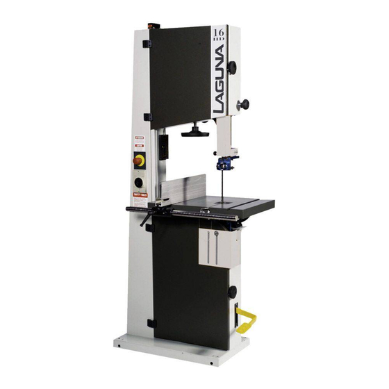
Table of Contents

Advertisement

LAGUNA BANDSAWS
16HD-37 MANUAL
LAGUNA TOOLS
2072 Alton Parkway
Irvine, California 92606
Ph: 800.234.1976
www.lagunatools.com
© 2017, Laguna Tools, Inc. LAGUNA® and the LAGUNA Logo® are the registered trademarks of Laguna Tools, Inc. All rights reserved.

Advertisement

Table of Contents
loading

Summary of Contents for laguna 16HD

  • Page 1 LAGUNA BANDSAWS 16HD-37 MANUAL LAGUNA TOOLS 2072 Alton Parkway Irvine, California 92606 Ph: 800.234.1976 www.lagunatools.com © 2017, Laguna Tools, Inc. LAGUNA® and the LAGUNA Logo® are the registered trademarks of Laguna Tools, Inc. All rights reserved.
  • Page 3: Table Of Contents

    Chapter 1.Safety rules and warranty Pg. 4-5 Chapter 2.Getting to know your bandsaw Pg. 6-13 Specification Pg. 6 Noise emission Pg. 7 Receiving your machine Pg. 7 Introduction to bandsaws Pg. 8 What you will receive with your machine Pg. 9 Parts of the bandsaw Pg.
  • Page 4 Read First!!! Safety Rules As with all machinery there are certain hazards involved with the operation and use. Using each one with caution will considerably lessen the possibility of personal injury. However, if normal safety precautions are overlooked or ignored, personal injury to the operator may result. If you have any questions relative to the installation and operation, do not use the equipment until you have familiarized yourself with the machine.
  • Page 5: Limited Warranty

    Machines sold through dealers must be registered with Laguna Tools within 30 days of purchase to be covered by this warranty. Laguna Tools guarantees all new machines and accessories sold to be free of manufacturers’...
  • Page 7: Noise Emission

    All damage must be noted on the delivery documents and signed by you and the delivery driver. You must then contact the seller [Laguna Tools] as soon as practical. If damage is found after delivery, contact the seller as...
  • Page 8: Introduction To Bandsaws

    Introduction to bandsaws This bandsaw is designed to give you years of safe service. Read this owner’s manual in its entirety before assembly or use. The bandsaw is generally defined as a saw blade in the form of an endless steel band that rotates around two or more wheels.
  • Page 9 What you will receive with the bandsaw. Tool Kit Fence, table insert, and door guard Table...
  • Page 10 Parts of the bandsaw The bandsaw does not have many parts. The major parts are discussed in this manual. If you are not familiar with the bandsaw, take the time to read this section and become familiar with the machine. Flywheel The blade is suspended over two wheels that are covered with rubber called a tire.
  • Page 11 Body The body of the bandsaw is a "U"-shaped frame, which houses all the parts of the machine. This is the heart of the bandsaw and has to be very rigid as it takes the strain of the blade being tensioned. Table The table supports the workpiece and can tilt to produce cuts at various angles.
  • Page 12 foot brake. Electrical connection This is achieved by connecting the electrical supply to a terminal box located at the back of the machine. Never connect directly to the electrical motor, and all electrical connections must be conducted by a qualified electrician. For detailed instructions see the assembly section of the manual.
  • Page 13: Where To Locate Your Bandsaw

    and, when rotated, will move the wheel up or down. The mechanism has a spring, which helps to keep the tension constant as the blade expands and contracts with the heat generated by the cutting action. The lower flywheel is also adjustable for tracking and has 4 bolts at the back of the machine that adjust the wheel shaft.
  • Page 14 Unpacking your machine To unpack your machine, you will need tin snips, knife and a wrench. Using the tin snips, cut the banding that is securing the machine to the pallet. WARNING: EXTREAM CAUTION MUST BE USED BECAUSE THE BANDING WILL SPRING AND COULD CAUSE INJURY. Lift the box off and discard.
  • Page 15 If no lifting device is available, the machine can be removed from the pallet as follows: Note: The machine is heavy, and if you have any doubt about the described procedure, seek professional assistance. Do not attempt any procedure that you feel is unsafe or that you do not have the physical capability of achieving.
  • Page 16: Mounting The Motor

    Mounting the motor Two people are required to assemble the motor to the bandsaw; build up wooden blocks to the right height to rest the motor on. One person holds the motor in position, and the other will fit the drive belt and the bolts.
  • Page 17 Mobility kit If you have purchased a mobility kit, now is the ideal time to fit it as the table has not been fitted to the machine and the bandsaw is lighter, but the mobility kit can be fitted later if you require it. Mobility kit assembly procedure Rest the bandsaw on a 2"...
  • Page 18 Installing the Table Two people are required to mount the table to the machine. Remove the lock-down bolt, handle and the pin from the trunnion. Position table trunnion, taking care not to damage any of the table or trunnion surfaces. While one person supports the table, the other person feeds the bolts and the lock down through the trunnion slots.
  • Page 19 too wide; this will ensure that the job is supported efficiently and safely. When the insert is replaced, you will have to sand the sides so that the insert fits correctly in the table hole. You will also have to cut the blade slot to suit your machine.
  • Page 20 The diameter of the dust collection port on the bandsaw is 4". Most US standard hoses are 4" in diameter. You can purchase a step-down adaptor from Laguna Tools or from your local hardware store in the plumbing or heating department if you...
  • Page 21 Bottom blade guard It is very important to have the blade covered for safety. A guard is provided at the top of the lower door. This guard must be moved vertically and clamped in position before operating the bandsaw. To open the door, the guard will have to be lowered.
  • Page 22 head, the door will not be able to be opened. Adjust the bolts so that the machine is level in both planes and does not rock.
  • Page 23 Electrical connection Note the machine is not supplied with an electrical cord or plug, as the size of the cable and the type of plug will be dependent on the installation. A qualified electrician must carry out the electrical installation. The main connection should be made using the terminal box shown.
  • Page 24 motor. The direction of rotation of machines with a single phase supply is predetermined during production. On a 3-phase machine the lower wheel must rotate in a clockwise rotation. If it rotates in a counterclockwise direction you need to swap locations of 2 of the power leads, and it will rotate in the correct direction.
  • Page 25 Before starting the machine Read and understand the instruction manual before operating the saw. If you are still not thoroughly familiar with the operation of the bandsaw, get advice from a qualified person. Make sure the machine is properly grounded and that the wiring codes are followed.
  • Page 26 Machine test Now is the time to test the machine. Yellow ring showing Close the doors. If you try to start the machine with the doors open, the machine will not start, as the safety switch is not engaged. Check that the foot break is in the fully up position.
  • Page 27 Adjusting the bandsaw Fitting a blade to the bandsaw A lot of people do not like to change the blades and go to great lengths to avoid doing it. To use the bandsaw to its greatest advantage, you will have to use the appropriate blade and track it quickly.
  • Page 28 Start rotating the wheels by hand in the normal direction. As you do this, watch blade Locking handle determine where the blade wants to track. If the blade is tracking forward backward, make small adjustments with the tracking adjustment knob located at the back of the bandsaw while still rotating the wheel.
  • Page 29 removed from the machine. Plug the machine into the power, turn the machine on for a second and switch off. Watch how the blade runs. If the blade tracks well, then run the machine at full power.
  • Page 30: Introduction

    Removing the blade from the band saw Disconnect power bandsaw. Remove the pin that aligns the two table halves. Open upper-hinged blade guard. Remove the table insert. Remove the tension on the upper flywheel. Open the doors and remove the blade from the wheels [use gloves and eye protection], and gently slide the blade through the table slot.
  • Page 31 The Laguna Guide eliminates this by supporting the blade above and below the back blade guide, giving the blade unsurpassed stability. The Laguna Guide also incorporates patented ceramic as the blade support material. The advantage of this material is its...
  • Page 32 Please read the following notes, as they will assist you in getting the optimum performance from your Laguna guide system. As with the roller guide systems, the Laguna guide system will damage your blade if it is not adjusted correctly. The guide blocks must not come in con tact with the teeth of the blade.
  • Page 33 the resin as the blade is moved through the guide blocks and keep that part of the blade clean. For this reason it is recommended that the blocks be adjusted as close to the gullet as possible but the teeth must not come in contact with the blocks as they will become damaged.
  • Page 34 Adjusting the blade guides The blade should run through the center of the rear blade guide, and the side guides should be parallel with the blade. If they have been moved out of adjustment, adjust as follows: Top upper side guides parallel adjustment. Loosen the clamp screw that attaches the guide to the vertical shaft and rotate the assembly until the side guide is parallel to the blade.
  • Page 35 Lower blade guide The lower blade guide is attached to a plate, which is slotted. The objective of the slots is to move the lower guide as close to the underside of the table as possible and give the blade maximum support. The shorter the distance that the blade is unsupported, the better the cut.
  • Page 36 Fitting cool block guide system [Optional, not supplied with the machine].
  • Page 37 This can be overcome to a great degree by using the Resaw king blade from Laguna. The blade has a lot of advantages such as superior surface finish to the cut, thin kerf [low wood wastage], can be re-sharpened, will cut hard woods and a long life.
  • Page 38 Adjusting the fence Method 1 Make a straight pencil line on the edge of a board. Feed the wood into the blade cutting next to the pencil mark. If the blade is drifting, you will have to compensate by angling the wood to keep the cut straight.
  • Page 39 Method 2 Set the fence parallel with the blade by loosening the clamp screws that hold it to the cast-iron bracket. It is not important that it is exact as you will be readjusting later in the procedure. Using a piece of scrap wood, make a cut while holding the wood against the fence.
  • Page 40 Resawing Resawing is the process of cutting a board in half along its height. The bandsaw is perhaps the most creative tool in the shop because of its ability to cut thick or thin, straight or curved. The ability to cut thick stock such as re-sawing, making veneers, book matching or cutting flitches from small logs has great appeal to the woodworker.
  • Page 42 Blades Introduction The selection and use of blades is a very extensive subject and there have been many books written on the subject. This section of the manual is intended as a general guide only. Selecting a blade Using the correct blade is important, as it is the first step in attaining good bandsaw performance.
  • Page 43 Pitch The size of the teeth. This is usually quoted in teeth per inch [T.P.I.] The larger the tooth, the faster the cut because the tooth has a large gullet and has a greater capacity to transport large amounts of sawdust through the job. The larger the tooth, the courser the cut and the poorer the surface finish of the cut.
  • Page 44 Width The dimension from the back of the blade to the front of the teeth. The wider the blade, the stiffer the blade and the straighter the cut. This is usually called beam strength. But wide blades cannot cut small radiuses. The narrower the blade, the more flexible the blade and the greater the tendency the blade has to wander.
  • Page 45 1" 2 T.P.I. This is a re-saw blade, which will be used for straight cuts and is suit able for processing veneers. If you are going to be cutting hard woods or require superb surface finish then you should consider purchasing a Resaw king blade from Laguna.
  • Page 46 With most guide systems it is recommended that the back of the blade be rounded with a stone. As the machine is supplied with Laguna ceramic guides, this is not imperative as the ceramic will round the back of the blade as it is used.
  • Page 47 Causes of the blade dulling Poorly set side guides and/or rear thrust guide.  Poor tracking.  Wrong blade selection. If the blade is too narrow, it will flex more easily and  decrease the quality of the cut. The blade should also have the correct pitch and width.
  • Page 48 Using a radius chart Until you become well acquainted with your saw it is best to use the contour (radius) chart to determine which size blade to use for a specific application. Radius charts can be found in many woodworking books, magazine articles, and on blade boxes.
  • Page 49 Maintenance and troubleshooting All tools and machines require regular maintenance, and the bandsaw is no exception. This section details the general maintenance and care of your bandsaw. In general, we recommend that you only use a Teflon-based lubricant on the bandsaw. Regular oil attracts dust and dirt and the Teflon tends to dry and has fewer tendencies to accumulate dirt and sawdust on your machine.
  • Page 50 Drive belt/s The drive belt should last for many years [depending on the usage] but needs to be inspected regularly for cracks, cuts and general wear. If damage is found, replace the belt. If your machine is a 2-belt system, then both belts must be replaced at the same time, as they are a matched pair.
  • Page 51 Rust The bandsaw is made from steel and cast iron. All non-painted surfaces will rust if not protected. It is recommended that the table and fence bar be protected by coating with wax if the machine is not in constant use. All moving non-painted surfaces [guides, rack and pinion, etc.] should be lubricated / protected with a Teflon- based lubricant.
  • Page 52 Vertical adjustment Mark the bolts so that you have a reference to their original position. If you get confused, you can go back to the original position. Correction for fig. A Loosen the shaft clamp screw that is positioned in the center of the 4 adjusting bolts. Loosen the top vertical bolt ¼...
  • Page 53 Correction for horizontal If the right-hand side of the wheel needs to come forward. Loosen the shaft clamp screw that is in the center of the 4 adjusting bolts. Loosen the bolt that is directly behind that side of the wheel ¼ turn and tighten the bolt opposite.
  • Page 54 Top guide vertical adjustment shaft The top guide when moved vertically tracks blade comes factory-set. Adjustment provided should that mechanism become misaligned. There is a plate at the top of the shaft with two bolts. This guides the top of the shaft. If the bolts are loosened the tracking of the guide can be adjusted.
  • Page 55 between 5L3 [red wire] and the red wire beside 2T1. To gain access to the terminals, you will have to remove the switch plate from the front of the machine. This circuit is a loop that has the foot brake, stop switch and door switch.
  • Page 56 Adjust rack and pinion. Bent rack. Replace the rack. Blade slows down during a cut Loose drive belt. Re-tension the belt. Dull blade. Replace the blade or have it re-sharpened. Feeding the wood too fast. Slow down the feed rate. Insufficient set on the teeth [wood nipping the blade].
  • Page 57: Chapter 7. Accessories

    Accessories The following accessories are available from Laguna Tools. Miter gage Mobility kit. Extension tables. Work benches. Tool cabinet [wall mounted]. Tool cabinet [floor standing]. Tool box. Bandsaw blades. Cool blocks. Cast-iron fence. Large Laguna Guides. Power feeder.
  • Page 58 Electrical system drawing with switch (ON) knob...
  • Page 59 Electrical system drawing with switch (ON) knob...
  • Page 60 Electrical system drawing with push (ON) button...
  • Page 61 Electrical system drawing with push (ON) button...
  • Page 62 Ordering spare-parts When ordering spare parts, specify: Machine Model and serial number. Part number required, taken from the exploded view drawing on the following page. Quantity required EXAMPLE: TO ORDER LOWER FLY WHEEL FOR LT16HD Model : LT16HD Part name: Lower fly wheel Serial number: 12345 Part number: 95 Quantity: 1 piece...
  • Page 66 TOP GUIDE BOTTOM GUIDE...
  • Page 67 Bandsaw LT 16 X 16 Drawing N° MACHINE CODE Part description 1 16-16 5020081 Upper fly wheel 2 16-16 3205040 Ball bearing 3 16-16 5210030 Spacer 4 16-16 3205040 Ball bearing 5 16-16 Washer UNI6593 ZNT M10 11x30x2,5 6 16-16 Seeger D=52 (hole) 7 16-16 5150089...
  • Page 68 53 16-16 included #50,51,52,49,54,55 54 16-16 Included #50,49,52,53,51,62 55 16-16 Included #50,49,52,53,54,51 56 16-16 3407257 Locking handle fence support 57 16-16 Screw TCEI 8.8 UNI5931 M8x25 58 16-16 Nut UNI5588 PG ZNT M10 59 16-16 5400604 V-Belt tensioning ( included #58,138 ) 60 16-16 3417006 V Belt, per unit...
  • Page 69 16-16 Washer UNI6592 ZNT M10 10,5x21x2 16-16 Locknut DIN985 PG ZNT M10 16-16 Washer UNI6593 ZNT M6 6,6x18x2 16-16 Screw TCEI 8.8 UNI5931 M6x20 16-16 Blind Rivet alluminium body 4x8 16-16 5210007 Plastic cover 16-16 5120010 Brake lining ( included #84 ) 16-16 Washer UNI6592 ZNT M8 8,4x17x1,6...
  • Page 70 16-16 Nut UNI5588 PG ZNT M12 16-16 Washer M12 12,5x28x3 16-16 1030344 No-rotation post plate 16-16 Screw TE 8.8 UNI5739 M6x16 16-16 5320100 Brake microswitch...
  • Page 71 Bandsaw LT18 X 18 Drawing N° MACHINE CODE Part description 18-18 5020089 Upper fly wheel 18-18 3205040 Ball bearing 18-18 5210035 Spacer 18-18 3205040 Ball bearing 18-18 Washer UNI6593 ZNT M10 11x30x2,5 18-18 Seeger D=52 (hole) 18-18 5150093 Upper door 18-18 5050065 Shaft upper wheel...
  • Page 72 18-18 included #50,51,52,49,54,55 18-18 Included #50,49,52,53,51,63 18-18 Included #50,49,52,53,54,51 18-18 3407257 Locking handle fence support 18-18 Screw TCEI 8.8 UNI5931 M8x25 18-18 Nut UNI5588 PG ZNT M10 18-18 5400602 V-Belt tensioning ( included #58,138 ) 18-18 3417008 V Belt, per unit 18-18 Motor pulley 18-18...
  • Page 73 18-18 Washer UNI6592 ZNT M10 10,5x21x2 18-18 Locknut DIN985 PG ZNT M10 18-18 Washer UNI6593 ZNT M6 6,6x18x2 18-18 Screw TCEI 8.8 UNI5931 M6x20 18-18 Blind Rivet alluminium body 4x8 18-18 5210007 Plastic cover 18-18 5120011 Brake lining ( included #84 ) 18-18 Washer UNI6592 ZNT M8 8,4x17x1,6...
  • Page 74 18-18 Nut UNI5588 PG ZNT M12 18-18 Washer M12 12,5x28x3 18-18 1030344 No-rotation post plate 18-18 Screw TE 8.8 UNI5739 M6x16 18-18 5320100 Brake microswitch...
  • Page 75 Bandsaw LT 20 X 20 Drawing N° MACHINE CODE Part description 20-20 5020097 Upper fly wheel 20-20 3205040 Ball bearing 20-20 5210031 Spacer 20-20 3205040 Ball bearing 20-20 Washer UNI6593 ZNT M10 11x30x2,5 20-20 Seeger D=52 (hole) 20-20 5150101 Upper door 20-20 5050067 Shaft upper wheel...
  • Page 76 20-20 Included #49,50,51,53,54,55 20-20 included #50,51,52,49,54,55 20-20 Included #50,49,52,53,51,64 20-20 Included #50,49,52,53,54,51 20-20 3407257 Locking handle fence support 20-20 Screw TCEI 8.8 UNI5931 M8x25 20-20 Nut UNI5588 PG ZNT M10 20-20 5400603 V-Belt tensioning ( included #58,138 ) 20-20 3417011 V Belt, per unit 20-20 Motor pulley...
  • Page 77 20-20 Nut UNI5588 PG ZNT M10 20-20 Washer UNI6592 ZNT M10 10,5x21x2 20-20 Locknut DIN985 PG ZNT M10 20-20 Washer UNI6593 ZNT M6 6,6x18x2 20-20 Screw TCEI 8.8 UNI5931 M6x20 20-20 Blind Rivet alluminium body 4x8 20-20 5210007 Plastic cover 20-20 5120012 Brake lining ( included #84 )
  • Page 78 20-20 Washer UNI6592 ZNT M10 10,5x21x2 20-20 Nut UNI5588 PG ZNT M12 20-20 Washer M12 12,5x28x3 20-20 1030344 No-rotation post plate 20-20 Screw TE 8.8 UNI5739 M6x16 20-20 5320100 Brake microswitch...
  • Page 79 Bandsaw Resawmaster Drawing N° MACHINE CODE Part description F50 - RSM 5020201 Upper fly wheel F50 - RSM 3205046 Ball bearing F50 - RSM 5210036 Spacer F50 - RSM 3205046 Ball bearing F50 - RSM Washer UNI6593 ZNT M10 11x40x2,5 F50 - RSM Seeger D=62 (hole) F50 - RSM...
  • Page 80 F50 - RSM included #50,51,52,49,54,55 F50 - RSM Included #50,49,52,53,51,69 F50 - RSM Included #50,49,52,53,54,51 F50 - RSM 3407257 Locking handle fence support F50 - RSM Screw TCEI 8.8 UNI5931 M8x25 F50 - RSM Nut UNI5588 PG ZNT M10 F50 - RSM 5400603 V-Belt tensioning ( included #58,138 ) F50 - RSM...
  • Page 81 F50 - RSM 5210009 Front aspiration outlet F50 - RSM Screw TCEI 8.8 UNI5931 M10x25 F50 - RSM 3401270 Lower door closing handle F50 - RSM Nut UNI5588 PG ZNT M10 F50 - RSM Washer UNI6592 ZNT M10 10,5x21x2 F50 - RSM Locknut DIN985 PG ZNT M10 F50 - RSM Washer UNI6593 ZNT M6 6,6x18x2...
  • Page 82 F50 - RSM Washer UNI6592 ZNT M10 10,5x21x2 F50 - RSM 1030382 Adjustment plate F50 - RSM Screw TE 8.8 UNI5739 M10x16 F50 - RSM Washer UNI6592 ZNT M10 10,5x21x2 F50 - RSM Nut UNI5588 PG ZNT M12 F50 - RSM Washer M12 12,5x28x3 F50 - RSM 1030344...
  • Page 83 Bandsaw LT 24 X 24 Drawing N° MACHINE CODE Part description 24-24 5020113 Upper fly wheel 24-24 3205046 Ball bearing 24-24 5210032 Spacer 24-24 3205046 Ball bearing 24-24 Washer UNI6593 ZNT M10 11x40x2,5 24-24 Seeger D=62 (hole) 24-24 5150105 Upper door 24-24 5050075 Shaft upper wheel...
  • Page 84 24-24 Included #49,50,51,53,54,55 24-24 included #50,51,52,49,54,55 24-24 Included #50,49,52,53,51,65 24-24 Included #50,49,52,53,54,51 24-24 3407257 Locking handle fence support 24-24 Screw TCEI 8.8 UNI5931 M8x25 24-24 Nut UNI5588 PG ZNT M10 24-24 5400602 V-Belt tensioning ( included #58,138 ) 24-24 3417010 V Belt, per unit 24-24 Motor pulley...
  • Page 85 24-24 Nut UNI5588 PG ZNT M10 24-24 Washer UNI6592 ZNT M10 10,5x21x2 24-24 Locknut DIN985 PG ZNT M10 24-24 Washer UNI6593 ZNT M6 6,6x18x2 24-24 Screw TCEI 8.8 UNI5931 M6x20 24-24 Blind Rivet alluminium body 4x8 24-24 5210007 Plastic cover 24-24 5120013 Brake lining ( included #84 )
  • Page 86 24-24 Screw TE 8.8 UNI5739 M10x16 24-24 Washer UNI6592 ZNT M10 10,5x21x2 24-24 Nut UNI5588 PG ZNT M12 24-24 Washer M12 12,5x28x3 24-24 1030344 No-rotation post plate 24-24 Screw TE 8.8 UNI5739 M6x16 24-24 5320101 Brake microswitch...
  • Page 87 Bandsaw LT 28 Drawing N° MACHINE CODE Part description 5020129 Upper fly wheel 3205046 Ball bearing 5210033 Spacer 3205046 Ball bearing Washer UNI6593 ZNT M10 11x40x2,5 Seeger D=62 (hole) 5150113 Upper door 5050075 Shaft upper wheel Screw TCEI 8.8 UNI5931 M10x20 Screw STEI UNI5927 M10x35 5030014 Sliding support upper wheel ( Group with #20)
  • Page 88 Included #49,50,51,53,54,55 included #50,51,52,49,54,55 Included #50,49,52,53,51,66 Included #50,49,52,53,54,51 3407257 Locking handle fence support Screw TCEI 8.8 UNI5931 M8x25 Nut UNI5588 PG ZNT M10 5400601 V-Belt tensioning ( included #58,138 ) 3417011 V Belt, per unit Motor pulley Electric motor : see separate price-list Washer UNI6593 ZNT M10 11x30x2,5 Screw TE 8.8 UNI5739 M10x35 Screw STEI UNI5923 M8x10...
  • Page 89 Screw TC-TC UNI8118 3,9x16 5210009 Front aspiration outlet Screw TCEI 8.8 UNI5931 M10x25 3401270 Lower door closing handle Nut UNI5588 PG ZNT M10 Washer UNI6592 ZNT M10 10,5x21x2 Locknut DIN985 PG ZNT M10 Washer UNI6593 ZNT M6 6,6x18x2 Screw TCEI 8.8 UNI5931 M6x20 Blind Rivet alluminium body 4x8 5210007 Plastic cover...
  • Page 90 Screw TE 8.8 UNI5739 M10x30 Washer UNI6592 ZNT M10 10,5x21x2 5150253 Table extension 1030382 Adjustment plate Screw TE 8.8 UNI5739 M10x16 Washer UNI6592 ZNT M10 10,5x21x2 Nut UNI5588 PG ZNT M12 Washer M12 12,5x28x3 1030344 No-rotation post plate Screw TE 8.8 UNI5739 M6x16 5320101 Brake microswitch...
  • Page 91 Bandsaw LT32 Drawing N° MACHINE CODE Part description 5020153 Upper fly wheel 3205048 Ball bearing 5210034 Spacer 3205048 Ball bearing Washer UNI6593 ZNT M10 11x40x2,5 Seeger D=72 (hole) 5150117 Upper door 5050081 Shaft upper wheel Screw TCEI 8.8 UNI5931 M10x20 Screw STEI UNI5927 M10x35 5030022 Sliding support upper wheel ( Group with #20)
  • Page 92 3450001 Included #50,49,52,53,54,60 Included #49,50,51,53,54,55 included #50,51,52,49,54,55 Included #50,49,52,53,51,67 Included #50,49,52,53,54,51 3407257 Locking handle fence support Screw TCEI 8.8 UNI5931 M8x25 Nut UNI5588 PG ZNT M10 5400601 V-Belt tensioning ( included #58,138 ) 3417014 V Belt, per unit Motor pulley Electric motor : see separate price-list Washer UNI6593 ZNT M10 11x30x2,5 Screw TE 8.8 UNI5739 M10x35...
  • Page 93 5010076 Table 5210005 Table insert Screw UNI5449 ZNT M6x16 5210102 Wooden Insert chute 1030637 Chute Screw TC-TC UNI8118 3,9x16 5210009 Front aspiration outlet Screw TCEI 8.8 UNI5931 M10x25 3401270 Lower door closing handle Nut UNI5588 PG ZNT M10 Washer UNI6592 ZNT M10 10,5x21x2 Locknut DIN985 PG ZNT M10 Washer UNI6593 ZNT M6 6,6x18x2...
  • Page 94 Washer M12 12,5x28x3 1030344 No-rotation post plate Screw TE 8.8 UNI5739 M6x16 5320102 Brake microswitch...
  • Page 95 Bandsaw LT37 Drawing N° MACHINE CODE Part description 5020170 Upper fly wheel 3205060 Ball bearing 5210039 Spacer 3205060 Ball bearing Washer UNI6593 ZNT M18 20x56x4 Seeger D=90 (hole) 5150121 Upper door 5050087 Shaft upper wheel Screw TCEI 8.8 UNI5931 M10x20 Screw STEI UNI5927 M10x35 Sliding support upper wheel ( Group with 5030026...
  • Page 96 Connection box ( included 5320150 #49,51,52,53,54,55 ) 3450001 Included #50,49,52,53,54,61 Included #49,50,51,53,54,55 included #50,51,52,49,54,55 Included #50,49,52,53,51,68 Included #50,49,52,53,54,51 3407257 Locking handle fence support Screw TCEI 8.8 UNI5931 M8x25 Nut UNI5588 PG ZNT M10 5400603 V-Belt tensioning ( included #58,138 ) 3417033 V Belt, per unit Motor pulley...
  • Page 97 Nut UNI5588 PG ZNT M6 Washer UNI6593 ZNT M6 6,6x18x2 5010083 Table 5210005 Table insert Screw UNI5449 ZNT M6x16 5210102 Wooden Insert chute 1030811 Chute Screw TC-TC UNI8118 3,9x16 5210009 Front aspiration outlet Screw TCEI 8.8 UNI5931 M10x25 3401270 Lower door closing handle Nut UNI5588 PG ZNT M10 Washer UNI6592 ZNT M10 10,5x21x2...
  • Page 98 Washer UNI6592 ZNT M10 10,5x21x2 Nut UNI5589 PF ZNT M18 Washer UNI6592 ZNT M18 19x34x3 1030753 No-rotation post plate Screw TE 8.8 UNI5739 M6x16 5320102 Brake microswitch...
  • Page 100 Laguna Tools is not responsible for errors or omissions. Specifications subject to change. Machines may be shown with optional accessories. © 2017, Laguna Tools, Inc. LAGUNA® and the LAGUNA Logo® are the registered trademarks of Laguna Tools, Inc. All rights reserved.

This manual is also suitable for:

Resaw masterLt18Lt32Lt24x24Lt28Lt24x17 ... Show all

Table of Contents