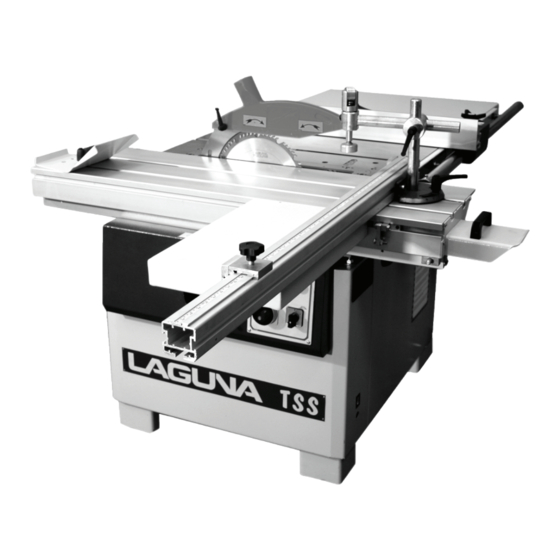
Download Print this page

Advertisement

TS / TSS Tablesaw
Manual
LAGUNA TOOLS
2072 Alton Parkway
Irvine, California 92606
Ph: 800.234.1976
www.lagunatools.com
© 2017, Laguna Tools, Inc. LAGUNA® and the LAGUNA Logo® are the registered trademarks of Laguna Tools, Inc. All rights reserved.
Model Number: MTSS000020

Advertisement

loading

Summary of Contents for laguna TS SERIES

  • Page 1 TS / TSS Tablesaw Manual LAGUNA TOOLS 2072 Alton Parkway Irvine, California 92606 Model Number: MTSS000020 Ph: 800.234.1976 www.lagunatools.com © 2017, Laguna Tools, Inc. LAGUNA® and the LAGUNA Logo® are the registered trademarks of Laguna Tools, Inc. All rights reserved.
  • Page 3: Table Of Contents

    Table of contents Safety Rules Warranty Noise emission Specification sheet Receiving your machine Unpacking your machine Introduction to your machine Assembly and set up Where to locate your machine Operating your machine Maintenance Troubleshooting Accessories Electrical drawing Spare parts Exploded view drawings and parts lists...
  • Page 4: Safety Rules

    Safety Rules As with all machinery there are certain hazards involved with the operation and use. Using it with caution will considerably lessen the possibility of personal injury. However, if normal safety precautions are overlooked or ignored, personal injury to the operator may result. If you have any questions relative to the installation and operation, do not use the equipment until you have contacted your supplying distributor.
  • Page 5: Limited Warranty

    Machines sold through dealers must be registered with Laguna Tools within 30 days of purchase to be covered by this warranty. Laguna Tools guarantees all new machines and accessories sold to be free of manufacturers’...
  • Page 6: Noise Emission

    Noise emission Notes concerning noise emission Given that there exists a relationship between noise level and exposure times, it is not precise enough to determine the need for supplementary precautions. The factors affecting the true level of exposure to operators are clearly the amount of time exposed, the characteristics of working environment other sources of dust and noise etc.
  • Page 7 Spare blank throat plate insert Standard equipment supplied with TS Rip fence Extension table with legs Blade guard Tool kit Options for TS Miter gauge Spare blank throat plate insert Sliding table Mobility kit Scoring unit Spare blank throat plate insert Standard equipment supplied with TSS Extension table with legs...
  • Page 8 TSS floor plan TS floor plan...
  • Page 9: Receiving Your Machine

    You need to do this prior to the driver leaving. All damage must be noted on the delivery documents and signed by you and the delivery driver. You must then contact the seller [Laguna Tools] as soon as practical. If damage if found after delivery, contact the seller as soon as practical.
  • Page 10 Cabinet The cabinet has a large footprint and is a welded construction manufactured from heavy gauge steel plate [4mm [0.16”] thick]. The cabinet houses all the parts of the machine and the heavy construction ensures that the saw is stable. This weight also helps to absorb any vibration that is produced during cutting.
  • Page 11 Sliding table. The sliding table is manufactured from heavy aluminum extrusion. The table is supported by ball bearings that roll on polished round steel rods. The clearance between the ball bearings and the polished round steel guide rods is adjustable. The advantage of the bearing system is that there is only point contact between the balls and the rods, which virtually eliminate the problem of dirt, building up and the sliding table will remain accurate for many years.
  • Page 12: Unpacking Your Machine

    Where to locate your machine. Before you remove your machine from the pallet select the area where you will use your machine. There are no hard and fast rules for its location but below are a few guidelines. 1/ There should be an area at the front and back of the machine suitable for the length of wood that you will be cutting.
  • Page 13 Fitting the optional mobility kit [If ordered] Slide the axel through the lower inside holes on the side of the machine and fit the spacer [large washer] onto the axel. Fit the wheel assembly, nut and washer on to the axel. To activate the moblity kit, insert the handle into the tube and rotate so that the machine is lifted.
  • Page 14 Assembly and set up What you will receive with the machine. Optional mobility kit Lifting hooks and tools Optional straight line rip bracket Fence system Miter fence Extension table and spare throat plate...
  • Page 15 Cleaning the machine. Remove the rust protection grease with WD 40 or similar solvent It is important that you remove all the grease and re lubricate with a Teflon bases lubricant as Teflon has less tendency to attract sawdust and cause clogging. You should also wax the table, as this also protects the cast iron from rust.
  • Page 16 Switch cover shown open To start your machine, release the red stop button by moving the button to the right. The door will be released and the green button will be accessible. Press the green button, and the machine will start. To stop the machine, press the red button. The machine should never be started with both motors engaged.
  • Page 17 To fit a blade, disconnect the saw from the power. Move the arbor to the maximum up position. Rotate the saw arbor so that the hole in the arbor lines up with the hole in the saw table. Insert the locking rod, and loosen the arbor nut. Remove the large clamping disc, and fit the blade.
  • Page 18 Leveling screws TS throat plate Insert The throat plate is made from cast iron, and has a phenolic insert. A spare insert is provided that you can machine to suite your requirements [Dado, Zero clearance, etc]. There are two types of throat plate, TSS and TS. To adjust the TS throat plate, adjust the leveling screws so that the throat plate is level with the table.
  • Page 19 loosening the clamp screw, and adjusting the jacking screws, the plate can be adjusted for level to the table, and for parallel to the table. Ensure that the clamping screws are tight before you use the saw. Retaining clip Insert TSS throat plate On the TSS, releasing the clips and sliding the insert towards the blade will remove the insert.
  • Page 20 Dado cuter Fitting the dado cutter Dado cutter To fit the dado cutter, disconnect the machine from the power and remove the arbor nut, clamping disc, and spacer. Fit the dado and lock in position with the clamp washer and arbor nut. Ensure that the lock rod is removed before you start the machine.
  • Page 21 Straight edge Extension table Jack screw Using a straight edge, adjust the legs so that with the straight edge flat on the main table the part of the extension table that is directly above the legs is level with the table. Above the table fixing bolts are leveling screws.
  • Page 22 Electrical connection Note the machine is not supplied with an electrical plug or cable, as the type of plug and cable, will be dependant on the installation. A qualified electrician must carry out the electrical installation. Switch box open Ground Fitting the electrical cable.
  • Page 23 13/ Hold the work piece firmly against the table. Do not attempt to saw stock that does not have a flat surface facing down. 14/ Use a push stick at the end of a cut. This is the most dangerous time, because the cut is complete and the blade is exposed.
  • Page 24 To fit the measurement tape. Assembling the measurement tape Marking the fence tube 1/ Clean the steel tube with solvent to remove all traces of grease and dirt. 2/ With a blade fitted, and the power disconnected from the machine, fit the fence to the tube and push it up against the blade so that it is just touching.
  • Page 25 Lublicate the non painted surfaces of the tube with wax or teflon lubricant. This will ensure that the fence runs smoothly and that the tube is protected from rust. Adjusting the fence vertically parallel to the saw table. Adjusting Wrench Squaring the fence The angle tube assembly will have to be adjusted vertically to ensure that the gap between the fence and the table is even along its travel.
  • Page 26 TSS sliding table Push pull handle The push pull handle is fitted under the table for shipping and will have to be removed and re fitted to the side of the table. To release the table, remove the red transport brackets [One at each end of the table] and withdraw the table lock knob.
  • Page 27 Optional straight line rip stop Adjusting screws Lock handles Fit the optional straight-line rip stop at the end of the table as shown. The optional side extension table, comes with the clamp bar attached. Loosen the ratchet handles and slide the bar into the slot on the side of the side of the sliding table. Attach the table and level as follows Straight edge Vertical adjusting screw To adjust the optional side extension table, lay a straight edge level on the sliding table,...
  • Page 28 Miter fence locking screw Miter fence flip stop hole The miter fence [Cross cut fence] is fitted into the sliding table slot and locating by tightening the lock screw into the hole in the table slot. Fit the clamp shaft through the casting into the “T”...
  • Page 29 Fine tuning the miter fence. Several methods are acceptable to fine-tune the fence but we have found that the following is a very practical way to achieve a square panel. 1/ Clamp the fence locked at 90 degrees against the stop. 2/ Clamp a sheet onto the sliding table and cut a straight edge [edge “A”].
  • Page 30 Optional miter gauge. Jack screw Clamp screw Optional miter gauge Dowel pin The miter gauge has an adjustable pointer; it also has a dowel pin that locks the miter gauge at 15-degree positions. The fence can be moved to different positions on the miter gauge to suit the job that you are doing.
  • Page 31 Vertical adjustment screw Vertical adjustment access hole Vertical adjustment screw Lining up the scoring unit Push the shaft through the casting so that the dowel pin lines up with the slot in the bush. Make sure that the spring is in position. Assemble the stop bushing, and the screw in the back of the casting.
  • Page 32 Motor support shaft Motor shaft nut Assemble the motor to the support shaft. Push the support shaft through the trunnion and tighten the nut ensuring that the washer is fitted. DO NOT OVER TIGHTEN THE NUT, AS THE MOTOR MUST BE ABLE TO MOVE.
  • Page 33 Fitting the scoring switch With the power disconnected, fit the switch and attach the wiring as detailed in the diagram at the back of the manual. Note. Never start the machine with both motors engaged at the same time. It will damage the magnetic contactor.
  • Page 34 Fit the scoring blade. Note. Scoring blades are supplied with shims that are used to adjust the width of the scoring blade, to suite the saw blade that you are using. Note. The scoring blade rotates in the opposite direction to the main blade. Adjust the blade so that it is 1/16’...
  • Page 35 Maintenance and troubleshooting All tools and machines require regular maintenance, and the table saw is no exception. This section details the general maintenance and care of your table saw. In general we recommend that you only use a Teflon based lubricant on the table saw. Regular oil attracts dust and dirt and the Teflon tends to dry and has fewer tendencies to accumulate dirt and saw dust on your machine .We also recommend that you wax the table to help prevent rust.
  • Page 36 Rust The table saw is made from steel and cast iron. All none painted surfaces will rust if not protected. It is recommended that the table be coated with wax. All moving none painted surfaces should be lubricated / protected with a Teflon based lubricant. Limit stop Limit stop Yellow dust cover...
  • Page 37 Do not attempt this procedure unless excessive movement has taken place during shipping. Top nut Sliding table adjustment Bottom nut 1/ Lock the sliding table in position with the table lock knob. 2/ Using a straight edge across the sliding table check the gap between the straight edge and the main table at both ends of the man table.
  • Page 38 A second way to check is to measure the distance between the miter slot and the slot in the sliding table. The miter slot is parallel with the saw blade and is a good reference point. If adjustment is needed proceed as follows. 1/ Loosen three of the lower clamp nuts.
  • Page 39 Sliding table ground steel rods damaged or warn. Remove end cover Clamp screws Steel rods If the steel rods become damaged or warn, a new face can be presented to the ball bearings as follows. 1/ Loosen the clamping screws at each end of the sliding table. 2/ With a brass rod, knock the rod out +_ 1”.
  • Page 40 3/ Check that the guide plate is not jamming. Clean and re lubricate. Ensue that you clean the whole guide plate by moving the saw arbor to fully up and fully down, cleaning the exposed part of the guide plate. 4/ Inspect the guide plate and bearing plate for ware and damage.
  • Page 41 Miter gauge slot to saw blade adjustment. Table spring pin Table adjustment bolt [Jack] Trunnion spring pin The table and the trunnion assembly are doweled to the body of the saw with 2 [each] spring pins. The pins stop movement during transport. The miter slot is factory set to run parallel with the saw blade, but, if movement has taken place during transportation of your saw, you will have to knock the spring pins through the table and the body of the saw, and loosen the table to body clamping screws.
  • Page 42: Troubleshooting

    Table dip in the middle. Note only adjust the table in very small steps over a period of time. Cast iron is a very brittle material and will break if over stressed. 1/ Lay an engineer’s straight edge across the table. 2/ Using feeler gauges measure the gap under the straight edge.
  • Page 43 Motor tries to start but will not turn. 1/ With the power disconnected from the machine. Try to turn the blade by hand. If the blade will not turn check the reason for the jamming. Typical reasons is wood jamming the blade.
  • Page 44 1/ Wrong blade for the job. 2/ Over feeding the job. 3/ Cutting painted wood or abrasive material. Accessories The following accessories are available from Laguna Tools. Miter gage. Mobility kit. Side extension tables for the TSS. Flip stops for the TSS miter fence.
  • Page 45 Electrical circuit...
  • Page 46 POWER FROM WALL (On-green) (Off-red) Contactor Yel/Green...
  • Page 47 Electrical diagram with scoring POWER FROM WALL (On-green) (Off-red) Contactor Black Black Switch Black Black Black Black Black Yel/Green Yel/Green...
  • Page 48 Parts breakdown for the TSS and TS table saws. Note. Some parts shown in this manual may vary with the parts delivered with your machine. We are constantly up grading the design of the machine and reserve the right to change the machine and / or the specification with out notice. Ordering spare-parts When ordering spare parts specify: Machine Model and serial number.
  • Page 49 BODY WITH PANEL AND REMOVABLE PANEL [TS]...
  • Page 50 BODY WITH PANEL AND REMOVABLE PANEL [TS] ST-01.01.01.00.00 BODY PS.00.00.09 SAFETY DEVICE NUT М12 DIN DIN 985 PULLEY АМ12 206-83 NUT М8 DIN DIN 985 PULLEY Ф9ХФ35Ф2,5 UN 732 BOLT М8Х25 1234-85 PS.00.00.03 STUD M12 SCREW М10Х30 2171-83 PULLEY АМ10 206-83 SCREW М10Х25 2171-83...
  • Page 51 BODY WITH PANEL [TSS]...
  • Page 52 BODY WITH PANEL [TSS] ST01.01.01.00.00 BODY SCREW М10X45 DIN 912 BDS 833-82 SPRING PULLEY 10Н PULLEY АМ10 BDS 206-78 ST01.01.00.00.13 BOLT ST01.01.00.00.14 STUD NUT М10 BDS 744-83 PULLEY Ф35ХФ10Х2.5 UN732 ST01-01.00.00.02 PANEL SCREW М6Х16 ISO 7380 BDS 833-82 SPRING PULLEY 6Н PULLEY АМ...
  • Page 53 LNR 460.00.00.00 Crosscut fence [Optional 18” long] LNR 230.00.00.07 Rotating body LNR 230.00.09.03 Special nut LNR 230.00.00.04 Pin Pulley АМ8 BDS 206-83 LNR 230.00.09.01 Strap LNR 230.00.00.03 Narrow Screw М4Х12 BDS 832-83 BDS 833-82 Spring pulley 4N Pulley АМ4 BDS 206-83 Screw М6Х8 DIN 7991 8.8 321.05П.00.01...
  • Page 54 LNR 230.00.00.00 Crosscut fence [Optional 9” long] LNR 230.00.00.07 Rotating body LNR 230.00.09.03 Special nut LNR 230.00.00.04 Pin Pulley АМ8 BDS 206-83 LNR 230.00.09.01 Strip LNR 230.00.00.03 Arrow Screw М4Х12 BDS 832-83 BDS 833-82 Spring pulley 4N Pulley АМ4 BDS 206-83 Screw М6Х8 DIN 7991 8.8 321.05П.00.01...
  • Page 55 LU.00.00.00 Rip fence [TS]...
  • Page 56 LAMINATED FENCE LU.11.00.07 SPRING LU.11.05.00 POINTER SCREW М6Х10 ISO 7380 NUT М6 DIN 985 SCREW М6Х20 DIN 603 SPRING PIN Ф5Х30 DIN 1483 SIGN LAGUNA TS LU.00.00.15 (T467) DIN 913 STOP SCREW M8X10 LU.11.01.07 PAD S=1 MM LU.11.01.11 PAD S=3 MM...
  • Page 57 LUMF.00.00.00 Sliding table rip fence [TSS]...
  • Page 58 GN719-38-M12 HANDLE SPRING PIN Ф4Х20 DIN 1481 LU.11.05.00 POINTER SCREW М6Х10 ISO 7380 LU.11.00.07 SPRING LU.11.00.02 LAMINATED FENCE SCREW М6Х20 DIN 603 LUMF.00.00.15 SIGN LAGUNA TSS (T 535) SPRING PIN Ф5Х30 DIN 1483 LU.11.01.07 PAD S=1 MM LU.11.01.11 PAD S=3 MM...
  • Page 59 LVC1219 – 00.00.00 CIRCULAR SAW MITER FENCE [TSS 4’ LONG]...
  • Page 60 LVC1219 – 00.00.00 CIRCULAR SAW MITER FENCE [TSS 4’ LONG] LVC600-00.00.02 COTTER LVC600-00.00.05 ARROW SCREW М6Х6 UN 6404 LVC600-00.00.03 LAMINATED FABRIC PAD LVC600-00.00.04 BASIS SCREW М8Х16 DIN 912 8.8 DIN 134 PULLEY ø10,5 xø22 x 2,5 DIN 127B PULLEY 2-8H GN603-78-M10-20-DGR HANDLE М10Х20 LVC600-00.00.28 SQUARED COTTER...
  • Page 61 LVC600 – 00.00.00 CIRCULAR SAW MITER FENCE [OPTIONAL 2’LONG]...
  • Page 62 LVC600 – 00.00.00 CIRCULAR SAW MITER FENCE [OPTIONAL 2’ LONG] LVC600-00.00.02 COTTER LVC600-00.00.05 ARROW SCREW М6Х6 UN 6404 LVC600-00.00.03 LAMINATED FABRIC PAD LVC600-00.00.04 BASIS SCREW М8Х16 DIN 912 DIN 134 PULLEY ø10,5 xø22 x 2,5 DIN 127B PULLEY 2-8H GN603-78-M10-30-DGR HANDLE М10Х30 LVC600-00.00.28 SQUARED COTTER LVC600.11.00.10...
  • Page 63 MF1270.03.00.00.00 SLIDING TABLE (MF) L=1270 [TSS]...
  • Page 64 MF1270.03.00.00.00 SLIDING TABLE (MF) L=1270 [TSS] S1270.03.00.00.01 SLIDING TABLE MOVABLE PART S1270.03.00.00.09 MOULDING S1270.03.00.00.11 SLIDING TABLE IMMOVABLE PART S1270.03.00.00.06 GUIDE DOWEL DS-3 (Ф8) BDS 12620-75 БДС 664-70 WOODEN SCREW 5Х45 S2300.09.02.01.00 SLIDING TABLE COVER SCREW М4Х12 DIN 963A S2300.09.00.00.03-01 COVER БДС...
  • Page 65 MUS.00.00.00 PLATE EXTENSION TABLE ОК.00.00.00 SUPPORT LEG [TSS &TS] 01.01.00.00.02 PANEL PULLEY АМ12 BDS 206-83 BOLT М12Х30 BDS 1234-85 MUS.01.00.00 EXTENSION TABLE 800X900 STOP SCREW М6Х16 DIN 913 ОК.00.00 SUPPORT LEG ОК.00.00 К34885 THRUST М8Х50...
  • Page 66 RC.00.00.00-T Scoring / [OPTIONAL TSS &TS]...
  • Page 67 RC.00.00.00-T Scoring unit [OPTIONAL TSS & TS] RC.00.00.12 RC.00.00.11 PRESSING PULLEY CIRCULAR SAW 120 Х 20 Х 2,5 OPTIONAL RC.00.00.07 ARBOR BDS 3389-83 STUD 1-6Х6Х16 BEARING 6004-2RS. C3 RC.00.00.06 BUSHING SCREW М10Х25 BDS 2171-83 RC.00.00.15 AXLE BOX BOLT М8Х25 BDS 1234-85 NUT М8 BDS 744-83 S2300.28.00.00.16 PIN...
  • Page 68 RCD 00.00.00 Scoring unit with DADO [OPTIONAL TSS &TS]...
  • Page 69 RCD 00.00.00 Scoring unit with DADO [OPTIONAL TSS &TS] Pos. Description Name Quan tity RC 00.00.12 RC 00.00.11 Pressing pulley Circular disk ø120 x ø20 x 2 1 RCD 00.00.04 Support DIN 1481 Spring pin ø5 x 18 RCD 00.00.06 Shaft DIN6885 A Feather 1-6x6x16...
  • Page 70 RC 00.00.25 Belt pulley RC 00.00.34 Pulley BDS1359-83 Screw M 5x16 DIN 7991 Screw M 8x20 Belt 20 х 1, L=510 S2300.28.00.00.19 Pulley S2300.28.00.00.20 Belt pulley DIN 471 Ring for shaft ø12 DIN 985 Nut M10 BDS2171-83 Screw M 8x25 RC 00.00.36 Lifting block RCD 00.00.46...
  • Page 71 SF 250M.08.00.00.00 BRACKET TABLE [TSS &TS] SF250M.08.00.00.01 SLIDE BLOCK PULLEY АМ10 BDS 206-83 GN603-73-M10-20DGR HANDLE EXTENSION TABLE 500Х320 SF2300.15.01.00.00 STOP SCREW М6Х16 BDS 1362-83...
  • Page 72 ST01-02.00.00.00 MAIN CIRCULAR SAW / 1-PHASE MOTOR 2,2kW [TSS & TSS]...
  • Page 73 ST01-02.00.00.00 MAIN CIRCULAR SAW / 1-PHASE MOTOR 2,2kW / GN6336.4-ST-40-M8-40 HANDLE М8Х40 KRMC-ST 11.01 SMALL HAND WHEEL FOR FOLDING HANDLE GN 698.3-26-М6 FLYWHEEL HANDLE, BLACK GN 698-KT-26-M10 FLYWHEEL HANDLE, BLACK SCREW М6Х12 DIN7991 БДС 832-83 SCREW М4Х10 БДС 833-82 PULLEY 2-4Н БДС...
  • Page 74 NUT М10 BDS 744-83 ST 01-02.00.00.58 COLOMN ST 01-02.00.59.00-02 MOTOR CRADLE / ESR 90L / DIN 7349 PULLEY ø17 X ø 40 X 6 NUT М16 DIN 985 MOTOR ST 01-02.00.00.63 BELT PULLEY BELT SPZ 630 MN, Lp≈Ld≈Lw= 630mm PULLEY Ф40ХФ24Х4 S2300.02.00.00.43 NUT М12 DIN 985...
  • Page 75 RING В70 BDS 2170-77 S2300.02.37.00.08 THRUST RING SCREW М8Х8 DIN 913 S2300.02.37.00.10 CARRIER S2300.02.37.00.13 BELT PULLEY PULLEY ø8 х ø35 х 2,5 UN 732 BDS 833-82 PULLEY 2-8Н SCREW М8Х20 BDS 2171-83 COTTER 8Х7Х20 BDS 3389-83 PULLEY ø20 х ø28 х 1 DIN 988 ...
  • Page 76 [OPTIONAL TSS] ST 01-10.00.03 COTTER ST 01.10.00.04 ST 01-10.00.05 THRUST LVC 600-00.00.10 COLOMN LVF 00.11.00.12 BODY HANDLE М8Х20 GN603-63-M8-20-DGR LVF.00.11.01.00 SUPPORT LVF 00.11.02.00-01 LEVER LVF 00.11.00.04 GUIDE DM5-321.40.30.14 SPRING RING В18 BDS 2170-77 LVF.00.11.00.10 AXIS S2300.10.00.00.03 ECCENTRIC S2300.10.00.00.02 STUD DIN319-KU-25-M8-C BALL 25...
  • Page 77 U – 00.00.00 Stop 90° [TSS] U-00.00.01 THRUST BOLT BDS 744-83 NUT-М8 SCREW М8Х12 DIN 913 SCREW М8Х16 DIN 915 У-00.04.00 BASIS BOLT М8Х30 BDS1230-85 У-00.00.02 STRAP ...
  • Page 78 Laguna Tools is not responsible for errors or omissions. Specifications subject to change. Machines may be shown with optional accessories. © 2017, Laguna Tools, Inc. LAGUNA® and the LAGUNA Logo® are the registered trademarks of Laguna Tools, Inc. All rights reserved.

This manual is also suitable for:

Tss seriesMtss000020