Table of Contents
Advertisement
Quick Links
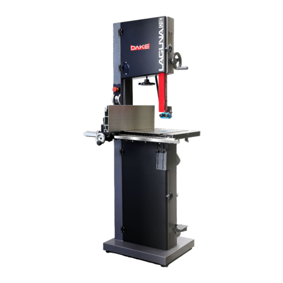
14CX METAL & WOOD VERTICAL BANDSAW
WARNING! Read and understand all instructions and responsibilities before operating.
Failure to follow safety instructions and labels could result in serious injury.
Laguna Tools, Inc.
744 Refugee Way
Suite 200
Grand Prairie TX, 75050
Phone: 800.332.4094
Website: lagunatools.com
Email: customer_service@lagunatools.com
INSTRUCTIONAL MANUAL
Dake Corporation
1809 Industrial Park Dr.
Grand Haven MI, 49417
Phone: 800.937.3253
Website: www.dakecorp.com
Email: customerservice@dakecorp.com
Advertisement
Table of Contents

Related Manuals for laguna Dake 14CX


Summary of Contents for laguna Dake 14CX
- Page 1 14CX METAL & WOOD VERTICAL BANDSAW INSTRUCTIONAL MANUAL WARNING! Read and understand all instructions and responsibilities before operating. Failure to follow safety instructions and labels could result in serious injury. Laguna Tools, Inc. Dake Corporation 744 Refugee Way 1809 Industrial Park Dr.
-
Page 2: Table Of Contents
Table of Contents RETURN & WARRANTY POLICY ....................... 3 SPECIFICATIONS ..........................5 SAFETY ..............................6 UNPACKING ............................10 MACHINE ASSEMBLY ........................11 Before First Time Start ........................12 Testing the Saw ..........................13 Blade Installation ..........................14 Tensioning the Blade ........................14 Blade Tracking / Top Idler Wheel Camber Adjustment .............. -
Page 3: Return & Warranty Policy
Machines sold through dealers must be registered with Laguna Tools within 30 days of purchase to be covered by this warranty. Laguna Tools guarantees all new machines sold are free of manufacturers’ defective workmanship, parts, and materials. - Page 4 Technical support to install replacement parts is primarily provided by phone, fax, e-mail, or Laguna Tools Customer Support Website. The labor required to install replacement parts is the responsibility of the user. Laguna Tools is not responsible for damage or loss caused by a freight company or other circumstances not in our control.
-
Page 5: Specifications
Maximum blade length 116" (2,946mm) Maximum blade width 3/4" (19mm) Minimum blade width 1/8" (3mm) Guides Laguna ceramic Height 70 1/2" (1,790mm) Machine Dimensions (W x D) 29-3/4" x 28" (755mm x 712mm) Base Footprint 22-11/16" x 17-9/16" (576mmx446mm) Machine Dimensions with mobility kit (W x D) 36 5/8"... -
Page 6: Safety
SAFETY Failure to comply with all warnings could lead to serious injury or death. Employer is responsible to perform a hazard/PPE assessment before work activity. English French WARNING: For your own safety, read instruction manual AVERTISSEMENT: Pour votre securite, lisez le manuel before operating bandsaw d'instruction attentivement avant d'utiliser la scie a ruban. - Page 7 SECURE WORK. Use clamps or a vise to hold bracelets, ou tout autre bijou ou accessoire qui pourrait etre entra1ne par des pieces mobiles Des souliers a work when practical. It is safer than using your semelle antiderapante sont egalement recommandes hand, and it frees both hands to operate tool.
- Page 8 GROUNDING INSTRUCTIONS 1. All grounded, cord-connected tools: In the event of a malfunction or breakdown, grounding provides a path of least resistance for electric current to reduce the risk of electric shock. This tool is equipped with an electric cord having an equipment-grounding conductor and a grounding plug.
- Page 9 Table A Ampere Rating Volts Total length of cord in feet More Than Not More Than Minimum gage for cord Not Recommended LOCKING OUT BANDSAW It is strongly recommended that the bandsaw is never unattended and unlocked. To lock the machine; fabricate a cover (not supplied) to cover the control panel. Below are two concepts for locking the panel.
-
Page 10: Unpacking
UNPACKING Before unpacking your machine ensure that there is no visible damage to the packaging. All damages must be noted on delivery documents signed by user and driver. Must report damages within 24 hours of delivery. Unpacking requires; tin snips, knife, and wrench. Note: The machine is heavy, and if you have any doubt about the described procedure, seek professional assistance. -
Page 11: Machine Assembly
MACHINE ASSEMBLY For instructional video follow link: https://www.youtube.com/watch?v=6zrMJ1aCrgI Or scan the QR code! 1. After making sure there is no damage to the outside of the packaging, proceed to open packaging and inspect internal contents for damage. 2. Remove all components from box, starting with this manual. Box contents include: user manual, fence, fence knuckle, hardware, cast iron table and the main saw assembly. -
Page 12: Before First Time Start
NOTE: The table has a reference stop bolt that is used to quickly align the table after tilting. The stop bolt hits the tilt-blanking disc when it is positioned over the table tilt hole. When the tilt blanking disc is moved away from the hole, it allows the tilt stop bolt to pass through the table tilt hole, and the table can be moved to the maximum amount of tilt (-7 degrees). -
Page 13: Testing The Saw
8. Make sure that the saw blade teeth point downward toward the table. 9. Adjust the upper blade guard so that it is just clearing the material being cut. 10. Make sure that the blade has been properly tensioned and tracked. 11. -
Page 14: Blade Installation
Blade Installation Disconnect the machine from the power source before making any adjustments. 1. Open the top door to the machine. Located on the back side saw head locate tensioner lever. 2. Lower the tension lever handle down to the minimum position. This will allow the wheel to drop. NOTE: (Sometimes, the upper wheel might stick in place over time after the tension handle is compressed. -
Page 15: Blade Tracking / Top Idler Wheel Camber Adjustment
Blade Tracking / Top Idler Wheel Camber Adjustment This adjustment aligns the tilt of the idler pulley with the drive pulley. If the wheel seems to be off centered, making noise, follow these steps to properly align the blade. 1. With your hand, rotate the upper wheel while looking through the window at how the blade tracks. Blade should track in the middle of wheels. -
Page 16: High To Low Setting & Fpm Setting
General Instructions: 1. Adjust blade guide assembly so that the blade guides are just above the workpiece (about 3/16”) allowing minimum exposure to the blade. 2. If using the fence, move it into position and lock it to the guide rail. If you are using the miter gauge for a crosscut, the fence should be moved safely out of the way. -
Page 17: Blade Speed Chart
Blade Speed Chart Speed Range Speed Range Material Material (FPM) (FPM) Structural Steel Shapes Bronze Low Carbon Steel 160-165 Al-Bronze Medium Carbon Steel Monel 40-45 High Carbon Steel 90-100 Titanium Alloy 25-40 Cr-moly Steel 105-135 Aluminum (soft) 3000 Ni-Cr-moly Steel 90-115 Aluminum (T-6+) 3000... -
Page 18: Squaring Table To Blade
Squaring Table to Blade 1. Check that the stop bolt is in contact with the tilt-blanking disc. 2. Place a square on the tabletop and bring it up to the side of the blade. 3. Check if the blade is square to the table. 4. -
Page 19: Optional Light Kit Installation
OPTIONAL LIGHT KIT INSTALLATION Laguna Part No: ALEDMACH Dake Part No: 303815 The light is attached to the top of the bandsaw as shown. The light is supplied with a three-pin plug to suit either 110V or 220V depending on machine voltage. The cable must be held in position with the clips provided and positioned so that the cable is safe and will not in any way come close to the blade or cabinet door. -
Page 20: Blade Selection
BLADE SELECTION This section of the manual is meant to be a refence guide only. If you are unsure which blade to use please contact your local blade supplier. Tell-tale Metal Chips Chips are the best indicator of correct feed force. Monitor chip information and adjust feed accordingly. -
Page 21: Causes Of Blade Dulling
Causes of Blade Dulling 1. Poorly set side guides or rear thrust guide. 2. Poor blade tracking. 3. Wrong blade selection. If the blade is too narrow, it will flex more easily and decrease the quality of the cut. The blade should also have the correct pitch and width. 4. - Page 22 The blade makes a clicking noise Bad weld. Dress the weld or change the blade. Blade overheats Dull blade. Change the blade or resharpen the blade. Pitch is too small for the depth of cut. Change to a blade with the correct pitch. Guides too tight.
-
Page 23: Maintenance
MAINTENANCE Before performing any maintenance to the machine, make sure to unplug the cord from the power source before cleaning. • Maintain bearing guides clean and free of build-up. • All bearings are sealed for life and do not require any maintenance. Replace bearings when faulty. Check that the cleaning brush over the band wheel is working properly and remove any deposits from the •... -
Page 24: Tire Maintenance
Tire Maintenance One of the major concerns regarding the maintenance of the bandsaw is how clean the tires are. As the saw cuts, some of the material lands on the tire of the lower wheel. As the wheel rotates, the material becomes compressed on the tire. -
Page 25: Replacing The Drive Belt
Replacing the Drive Belt 1. Loosen the motor clamp bolts and move the motor so that the tension is completely removed from the drive belt. Remove the blade. Loosen the two hex nuts that hold the brake to the bandsaw frame and slide it out of the way of the disc. 2. -
Page 26: Wiring Diagrams
WIRING DIAGRAMS: 14CX REV#072023... - Page 27 14CX REV#072023...
-
Page 28: Parts List
PARTS LIST Upper Wheel Assembly: Pos. Part # Description PBAND1412-175-1 Hex Nut (M14x1.5-LH) PBAND1412-175-2 Ball Bearing (6202LLU) PBAND1412-175-3 C-Ring (R35) PBAND1412-175-4 PU Tire PBAND1412-175-5 Upper Wheel PBAND1412-175-6 Upper Wheel Shaft PBAND1412-175-7 Upper Wheel Shaft Bracket PBAND1412-175-8 Special Nut PBAND1412-175-9 Socket Head Cap Screw (3/8"-16x5/8") PBAND1412-175-10 Support Bracket PBAND1412-175-11... - Page 29 PB14CX-47 Saw Body PBAND1412-175-48 Lock Knob PBAND1412-175-49 Adjusting Knob PBAND1412-175-50 Tension Label PBAND1412-175-51 Upper Door PB14CX-52 Logo Label, LAGUNA PBAND1412-175-53 Hinge Cover PB14CX-54 Emergency Stop PBAND1412-175-55 Warning Label (not shown) PBAND1412-175-2-13 Lock Washer (5/16") Logo Label, DAKE PB14CX-58 Flange Nut (5/16"-18) PBAND1412-175-59 Carriage Bolt (5/16-18x5/8")
- Page 30 Pos. Part # Description MBAND14BX110-175-63 Handle PB14CX-64 Spacer PB14CX-65 Screw (M3x0.5x15) MBAND14BX110-175-66 Plate(110V) MBAND14BX110-175-67 Washer, Lock-Int. Tooth (M4) MBAND14BX110-175-68 Screw (M4x0.7x8) PLAREVO1836-1156 O-Ring (P14) PB14CX-70 Bracket PLAREVO1836-159 Speed Knob O-Ring (P29) PLAREVO1836-1143 Digital Readout PB14CX-73 Set Screw (M4x0.7x4) PLAREVO1836-1100 14CX REV#072023...
-
Page 31: Lower Wheel & Motor Assembly
Lower Wheel & Motor Assembly: Pos. Reference # Description PBAND1412-175-1 Hex Nut (M14x1.5-LH) PBAND1412-175-2 Ball Bearing (6202LLU) PBAND1412-175-3 C-Ring (R35) PBAND1412-175-4 PU Tire PBAND1412-175-5 Upper Wheel PB14CX-2-6 Poly-V Belt PB14CX-2-7 Motor Pulley PBAND1412-175-2-8 Set Screw (5/16"-18x3/8") PB14CX-2-9 Key (5x5x60) PB14CX-2-10 Flat Washer (1/4") PBAND1412-175-2-11 Flat Washer (5/16") - Page 32 Pos. Reference # Description PBAND1412-175-25-2 Door Hinge, Right 24.2 PBAND1412-175-25-3 Socket Head Cap Screw (M5x0.8x35) 24.3 PBAND1412-175-25-4 Nylon Inserted Lock Nut (M5x0.8) 24.4 MBAND14BX110-175-2-25 Lower Door PBAND1412-175-2-26 Lock Knob PBAND1412-175-2-27 Lower Blade Guard PBAND1412-175-2-28 Screw (1/4"-20x3/4") PBAND1412-175-2-29 Plate PBAND1412-175-32 Hex Nut (1/4"-20) PBAND1412-175-33 Door Stud PBAND1412-175-2-32...
- Page 33 Pos. Reference # Description MBAND14BX110-175-2-63P Brake Pad (not shown), 2 pieces PB14CX-2-64 Disc MBAND14BX110-175-2-65 Inner Cable (not shown) MBAND14BX110-175-2-66 Housing (not shown) MBAND14BX110-175-2-67 Plate PBAND1412-175-5-7 Socket Head Button Screw (3/8"-16x1") PBAND1412-175-5-8 Rubber Pad MBAND14BX110-175-2-70 Socket Head Button Screw (M5x0.8x12) MBAND14BX110-175-68 Screw (M4x0.7x8) MBAND14BX110-175-2-72 Spacer...
- Page 34 Table and Fence Assembly Pos. Part # Description PBAND1412-175-3-1 Aluminum Fence PBAND1412-175-3-2 Plastic Adjusting Screw PBAND1412-175-3-3 Fence Body PBAND1412-175-3-4 Lock Knob PBAND1412-175-3-5 Socket Head Cap Screw (5/16"-18x3/4") PBAND1412-175-2-13 Lock Washer (5/16") PBAND1412-175-3-7 Fence Head PBAND1412-175-3-8 Lock Knob PBAND1412-175-3-9 Lock Bar PBAND1412-175-3-10 Set Screw (M4x0.7x4) PBAND1412-175-3-11...
- Page 35 Pos. Part # Description PBAND1412-175-3-17 Bushing PBAND1412-175-3-18 Socket Head Cap Screw (5/16"-18x2") PBAND1412-175-3-19 Steel Tube PBAND1412-175-3-20 Scale PBAND1412-175-3-21 Trunnion PBAND1412-175-3-22 Hex Cap Screw (M10x1.5x50) PBAND1412-175-3-23 Slide Block PBAND1412-175-3-24 Flat Washer (1/4") PBAND1412-175-42 Lock Washer (1/4") PBAND1412-175-3-26 Socket Head Cap Screw (M6x1x16) PBAND1412-175-3-27 Pointer PBAND1412-175-3-28...
-
Page 36: Upper & Lower Blade Guides Assembly
Upper & Lower Blade Guides Assembly Pos. Part # Description PBAND1412-175-4-1 Lock Knob PBAND1412-175-2-8 Set Screw (5/16"-18x3/8") PBAND1412-175-43 Set Screw (1/4"-20x3/8") PBAND1412-175-4-4 Hand wheel PBAND1412-175-4-5 Handle PBAND1412-175-4-6 Pointer PBAND1412-175-4-7 Screw (1/4"-20x3/8") PBAND1412-175-4-8 Upper Blade Guard PBAND1412-175-4-9 Height Scale PBAND1412-175-4-10 Magnet PBAND1412-175-4-11 Guide Bar Bracket PBAND1412-175-4-12... -
Page 37: Ordering Information
To order parts please contact the distributor or representative responsible for the sale ORDERING INFORMATION Parts are available for direct purchase from Dake/Laguna or through a distributor. When placing a parts order, you will need to provide the part number, name of part, and model number.
Need help?
Do you have a question about the Dake 14CX and is the answer not in the manual?
Questions and answers