Table of Contents
Advertisement
Advertisement
Table of Contents

Subscribe to Our Youtube Channel
Related Manuals for Danfoss AK-SM 850


Summary of Contents for Danfoss AK-SM 850
- Page 1 MAKING MODERN LIVING POSSIBLE AK-System Manager AK-SM 850 User Guide v1.0...
-
Page 2: Table Of Contents
Lighting Configuration .................52 Boolean Logic / Calculations ..............55 Energy Configuration ................57 Modbus Port on AK-SM ................59 Enterprise Load Shed (via Danfoss EDS Service) ......61 Demand Limiting ..................62 General navigation, operation and use (via web) .......63 Connecting to your AK-SM: ............63 Dashboard view: ................63... -
Page 3: Document History
Document revision Document History Document Notes USCO.PI.R1.E1.02 First document release AK-SM 850 User Guide USCO.PI.R1.E1.02 © Danfoss 07-2013 Lit. no. -
Page 4: Product Introduction
Remotely manage your system - Update software, save database, controller file management, load images, allowing custom image & mapping of parameters Service Tool support Gain access to Danfoss AK2 based controls via Service Tool tunneling User Guide USCO.PI.R1.E1.02 © Danfoss 07-2013 AK-SM 850 Lit. -
Page 5: Ordering
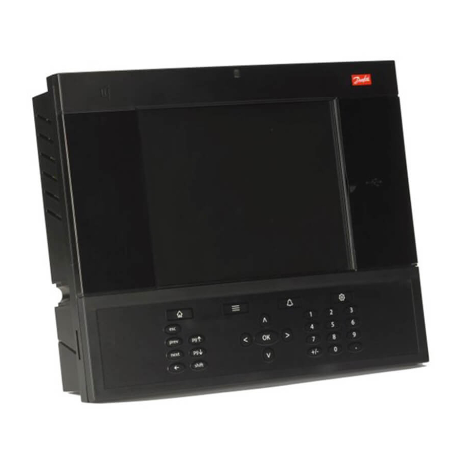
Lon RS485 Screen Specifications The mounting location should be flat, dry and free of major vibra- Operating temperature: tions. The AK-SM 850 should be mounted at eye level. Screen: -10 to +55˚C (14 to 131˚F) Dimenstions: @ 90% RH (non condensing) Unit Width 295 mm (11.6”) -
Page 6: Installation
Small slotted screwdriver for connector screws Torx 8 screwdriver for releasing the electronic unit and for fastening the unit when recessed mounted Screwdriver for fixating the AK-SM 850 Pen for marking the 2 lower fixation holes Larger slotted screwdriver for releasing the Technician lid... - Page 7 Wall Mounting- Panel recessed From the front: A hole of the size 280 x 220mm is machined The AK-SM 850 is inserted in the hole From the backside: Slide the 3 fastener into the housing part The screws are inserted into the fasteners...
-
Page 8: Connections
Connections The following chapter describes the available connections on your AK-SM 850. Please note that not all connection points are currently active, please refer to the drawing below for more details not currently not currently used used Modbus field Lon (RS485) - Page 9 The screen must not be connected to anything else. (The screen is earthed inside the screen and must not be earthed in any other way.) AK-SM 850 User Guide USCO.PI.R1.E1.02 © Danfoss 07-2013 Lit. no.
- Page 10 The screen must be connected to the system device, all controller and any repeaters. A screen must always be looped from device to device. The screen must not be connected to anything else. User Guide USCO.PI.R1.E1.02 © Danfoss 07-2013 AK-SM 850 Lit. no.
-
Page 11: Remote Management Tool (Rmt)
• Tools Download System software, backup (save) & load database files. • Language Compatible in multi- languages The RMT tool is available from your Danfoss sales office with associated supporting documentation. AK-SM 850 User Guide USCO.PI.R1.E1.02 © Danfoss 07-2013 Lit. no. - Page 12 Open FTP server ports to the public internet is not considered as a safe network practice. To avoid these issues, Danfoss strongly suggests FTP functionality in LAN network only . This would reduce the risk of open FTP ports and enhance network security.
-
Page 13: Initial Configuration - Language
3/ Using the down arrow, navigate to the Language line and select your required language 4/ Select your language for ‘Display’. The unit will then request a reset. Select language Display language AK-SM 850 User Guide USCO.PI.R1.E1.02 © Danfoss 07-2013 Lit. no. -
Page 14: Initial Configuration - Wizard
The following section describes the current Web Wizards, used for simplifying initial settings and Refrigeration layout. The Web Wizards can be used in an offline or online configuration. Danfoss recommends using the AK-SM web environment for commission tasks. Establish a web connection to your AK-SM (if working online, enter the valid IP address of the AK-SM and apply the factory user name and password). - Page 15 ‘No Compressor’. When the final wizard screen is presented any standalone controls can be mapped under this ‘No Compressor’ group. The ‘Circuits’ screen follows the same principle as the Compres- sors screen. AK-SM 850 User Guide USCO.PI.R1.E1.02 © Danfoss 07-2013 Lit. no.
- Page 16 Typically some additional configuration tasks will then need to be completed (i.e. define alarms, setpoint changes, configure history), please refer to the following section for further details on detailed configuration. User Guide USCO.PI.R1.E1.02 © Danfoss 07-2013 AK-SM 850 Lit. no.
-
Page 17: Configuration
(AK-SM), with field bus I/O. De-centralized control is the the AK-SM web browser interface, but would equally apply if term used to describe the full support of Danfoss Pack and Case being done via the local screen. Further detailed commissioning controllers. - Page 18 The text on the screen will reflect the scan progress, after a scan the time & date will be shown (indicating last scan) For SLV support, select Modbus channel User Guide USCO.PI.R1.E1.02 © Danfoss 07-2013 AK-SM 850 Lit. no.
- Page 19 OI (Output|Input) RO (Relay output) SI (Sensor Input) V02 (Variable output) Utility Meter (WattNode, Veris, Carlo Garvazzi) Generic (Danfoss case / pack controllers) AK-CM (AK- Communication Modules) Calculations Each node (type) has a column that reflects any configured or scanned status.
- Page 20 Once new auth types have been created, enter custom name and define level of access by selecting the Settings line (Authoriza- tion pop up box will appear) User Guide USCO.PI.R1.E1.02 © Danfoss 07-2013 AK-SM 850 Lit. no.
- Page 21 Manual Operation (seen under Service tab in device detail page) Refrigeration: Allow user to perform the following operations on Danfoss case controllers ; Main Switch, Defrost, Cleaning, Lights, Night Setback, Shutdown HVAC: Allow user to perform the following operations to Relay, Inputs &...
- Page 22 The Alarms screen has a sub set of screen [Connections, Service, Alarm Routing, Relays, System, I/O Comm]. Go through each sub tab to ensure all areas are correctly configured as per site requirements. Define the number of AK-SM system The AK-SM utilizes an If Controllers (Danfoss Evap & connections (typically based alarm Alarm Action Matrix that Pack, Power meters) and, I/O...
- Page 23 RMT. Where Internet / Intranet connection is not available, Danfoss recom- mends considering 3G as a means of offering IP connectivity. Please consult your local Danfoss sales office with regard to 3G connectivity. AK-SM 850 User Guide USCO.PI.R1.E1.02 ©...
- Page 24 • 2 Network connections • 6 IP / e-mail addresses (3 per alarm receiver) The following example can be seen as a guide to configuring your AK-SM alarm logic options; User Guide USCO.PI.R1.E1.02 © Danfoss 07-2013 AK-SM 850 Lit. no.
- Page 25 Alarm output options Set pre delay, duration and stop conditions (for each Select the appropriate alarm output selection) ‘component’ (i.e relay, network) and configure by double clicking on the appropriate line AK-SM 850 User Guide USCO.PI.R1.E1.02 © Danfoss 07-2013 Lit. no.
- Page 26 Clear = Stop when alarm clears Time/Rep = Stop after time delay but repeat if alarm is still active Ack/Rep = Stop after alarm is acknowledged. If alarm still active active after acknowledge repeat User Guide USCO.PI.R1.E1.02 © Danfoss 07-2013 AK-SM 850 Lit. no.
- Page 27 Ram Disk Full: Alert alarm if Ram is getting full (due to EDF files) Factory settings can be changed as per customer requirements. Alarm level & Actions can be changed AK-SM 850 User Guide USCO.PI.R1.E1.02 © Danfoss 07-2013 Lit. no.
- Page 28 I/O Comm tab If Controllers (Danfoss Evap & Pack, Power meters) and, I/O has been used in the control configuration (Lighting, HVAC, Refrigera- tion etc.), these devices can be seen under the I/O Comm tab. The I/O Comm tab allows any offline communication alarms to be configured.
- Page 29 Please also note that the SM provides the ability to configure centralized or de-centralized control. Centralized control is where your SM has the control logic built in and uses Danfoss I/O to provide refrigeration control. De-centralized is the control method via the use of Danfoss Pack and case controllers...
- Page 30 Configuration->Network Nodes tab Set a custom name for your control devices Enter address that matches the physical address in the pack and case controllers See above note about Download / Upload User Guide USCO.PI.R1.E1.02 © Danfoss 07-2013 AK-SM 850 Lit. no.
- Page 31 By navigating through all the controller screens in the AK-SM it is possible to configure the controller parameters and then send these setting to the connected controllers via the download function. AK-SM 850 User Guide USCO.PI.R1.E1.02 © Danfoss 07-2013 Lit. no.
- Page 32 By changing the overview value the AK-SM will then display the new selected parameter or status in the system view, Dashboard and device detail pages. User Guide USCO.PI.R1.E1.02 © Danfoss 07-2013 AK-SM 850 Lit. no.
- Page 33 When selecting the auto configure history function the AK-SM presents the option to select the history collection sample rate. These can be later changed & modified under the relevant history device type (Controllers/Relays/ Sensors/On/Off/Variable/Other) AK-SM 850 User Guide USCO.PI.R1.E1.02 © Danfoss 07-2013 Lit. no.
- Page 34 1,2,10,30 mins 1 Hr Relays, Sensors, On/Off Inputs, Variable Outputs & Other Depending on the defined control criteria, other points may be viewed and modified under the respective tabs. User Guide USCO.PI.R1.E1.02 © Danfoss 07-2013 AK-SM 850 Lit. no.
-
Page 35: Service Tool Support
Service Tool Support Your AK-SM supports the Danfoss Service Tool (version 3.23 and higher). The Service Tool (CT) must be connected via an IP interface. Once an connection is established the ST will show the AK-SM and all AK2 platform devices. Note that non AK2 platform based devices will not show up in the ST device list. -
Page 36: Master Control Functions
1 - Use a Night Setback Schedule (Configuration->Refrigeration->Rail Heat) Many Danfoss controls have a function whereby the output to the rail heat elements can be pulsed in a percentage of time ratio. If set in the controller, the night setback signal from the AK-SM will allow the controller to vary the output depending on the time period. - Page 37 (5 mins on, 5 mins off) At 7.0°c Dewpoint the relay output will be 90% of the cycle time (9 mins on, 1 min off) Relay output percentage (based on cycle time setting) AK-SM 850 User Guide USCO.PI.R1.E1.02 © Danfoss 07-2013 Lit. no.
- Page 38 The following section highlights how to configure active rail heat via the Danfoss AK-CC550 evaporator controller (which has the ability to utilize calculated dew point over the communications bus). Select ‘Yes’ to the question line ‘Use Adaptive Rail heat’ , and (in this example) select ‘Calculated Dewpoint’...
-
Page 39: Schedules
In the area between the two dew point values the controller will manage the power to the rail heat Schedules used in combination with Danfoss controllers) Configuration->Control->Refrigeration->Schedules Under the schedules section multiple schedules can be added and configured according to your needs. - Page 40 Once all configuration of the schedule is complete, navigate back to the Schedules tab & select ‘Enable this schedule’ to YES Use the ‘Enter’ key to select or not select any controller(s). User Guide USCO.PI.R1.E1.02 © Danfoss 07-2013 AK-SM 850 Lit. no.
-
Page 41: Suction Pressure Optimization
The Po Optimize function uses a calculation on all controllers to data is collected that tells the system which refrigeration determine a “Load Factor”. This has been developed by Danfoss appliances are most heavily loaded. This energy saving function and is available in your AK-SM. By use of the Load Factor the Most can make substantial savings directly whilst also saving on Loaded Case (MLC) is constantly updated. - Page 42 (optimization tab)- refer to (local screen) examples below. If your AK-SM is configured for degrees C, Suction Optimization is “K”. If set to degrees F Suction Optimization is “F”. User Guide USCO.PI.R1.E1.02 © Danfoss 07-2013 AK-SM 850 Lit. no.
-
Page 43: Akc On (Evap Shutdown When Injection Off)
Evap shutdown when injection off to ‘YES’ Evap Configuration If the Evap is not required to be part of the AKC ON function, modify the question Evap shutdown when injection off to ‘No’ AK-SM 850 User Guide USCO.PI.R1.E1.02 © Danfoss 07-2013 Lit. no. -
Page 44: Miscellaneous Configuration
Configuration -> Control -> MISC The term Miscellaneous refers to the ability to monitor and control miscellaneous areas of an application using Danfoss AK I/O (modules). For example, a miscellaneous relay output may be required for an exhaust fan, a dispenser that adds chemicals, an oven, a produce fogger, or any other device that can’t or... - Page 45 Days: Define the days associated with alarm Action: Define the alarm action Any Misc points configured in the AK-SM system will be shown in the ‘System View’ under the Power/Misc window AK-SM 850 User Guide USCO.PI.R1.E1.02 © Danfoss 07-2013 Lit. no.
- Page 46 Days: Define the days associated with alarm Action: Define the alarm action Sensor fail alarms: Enter the alarm level to issue alarm if sensor fails (Disabled, Log only, Normal, Severe, Critical) User Guide USCO.PI.R1.E1.02 © Danfoss 07-2013 AK-SM 850 Lit. no.
- Page 47 Delay: Enter delay time Units: Seconds, Minutes, Hours From: Defines alarm output time window To: Defines alarm output time window Days: Define the days associated with alarm Action: Define the alarm action AK-SM 850 User Guide USCO.PI.R1.E1.02 © Danfoss 07-2013 Lit. no.
- Page 48 Delay: Enter delay time Units: Seconds, Minutes, Hours From: Defines alarm output time window To: Defines alarm output time window Days: Define the days associated with alarm Action: Define the alarm action User Guide USCO.PI.R1.E1.02 © Danfoss 07-2013 AK-SM 850 Lit. no.
- Page 49 AK-XM 103A Variable Output board Your AK-SM fully supports the family of Danfoss I/O modules. The I/O family consists of various analog inputs, digital outputs, and relays. New to the I/O family is the AK-XM 103A (080Z0032) analog input /output module. This new module offers x4 analog inputs and x4 analog outputs, allowing easy control of a variety of control applications.
- Page 50 Units: Select from a range of unit types: °F °C ppm (Parts Per million) V (Volts) gpm (gallons per min) lpm (litres per minute) lps (litres per second) Minimum Input: Maximum Input: Minimum output: Maximum output: Lux: User Guide USCO.PI.R1.E1.02 © Danfoss 07-2013 AK-SM 850 Lit. no.
-
Page 51: Managers Override
Then make sure to configure the board & point with the same board and point number used for the actual override box, and set the Bcast point to Rec. AK-SM 850 User Guide USCO.PI.R1.E1.02 © Danfoss 07-2013 Lit. no. -
Page 52: Lighting Configuration
Lighting Configuration Configuration -> Control -> LIGHT Your AK-SM has the built in ability to support lighting scheules and control via Danfoss I/O modules or via lighting panel communications. Typically the built in lighting control function is used to manage general store lighting applications. - Page 53 Minimum output (0.0v): The minimum dimmer level. Maximum output (10.0v): The maximum dimmer level. Algorithm sensitivity: Algorithm interval: Max rate of change (% / Sec): AK-SM 850 User Guide USCO.PI.R1.E1.02 © Danfoss 07-2013 Lit. no.
- Page 54 After the relevant Lighting control questions and appropriate AK I/O addresses have been applied, check the alarms tab. Depend- ing on the Lighting control configuration alarm points will be seen under the alarm tab. User Guide USCO.PI.R1.E1.02 © Danfoss 07-2013 AK-SM 850 Lit. no.
-
Page 55: Boolean Logic / Calculations
***Press to insert new line ****. You will see this done in a few pages during the presentation of our first example. Heading Data Definitions Rules Area ‘Else’ line AK-SM 850 User Guide USCO.PI.R1.E1.02 © Danfoss 07-2013 Lit. no. - Page 56 1/ Creating the miscellaneous points for this calculation- Sensor inputs: Create 3 sensor inputs (the 3rd is used to display the average through the calculation). User Guide USCO.PI.R1.E1.02 © Danfoss 07-2013 AK-SM 850 Lit. no.
-
Page 57: Energy Configuration
Detailed configuration is done under the Energy tab (Configura- The Danfoss approved power meters can be seen when selecting tion->Control->Energy) meter type under the control question in Configuration->Control page and are described in the example below. - Page 58 (when using normal power). There is one field for each hour of the day, from 00 to 23. This screen has two pages in order to list all the hours of the day. User Guide USCO.PI.R1.E1.02 © Danfoss 07-2013 AK-SM 850 Lit. no.
-
Page 59: Modbus Port On Ak-Sm
Modbus channel if 9600- consult the meter manual for specific information on how to an existing network of Danfoss EKC modbus devices is estab- set the network address & baud rate. The data format is 1 start bit, lished. - Page 60 Configuration -> Control -> ENERGY [Danfoss Supported Power meter] This example highlights a Danfoss supported meter WattNode + Modbus. Having already defined the power meter as ‘WN Plus/ MB’ under the control page, navigate to the Configuration- >Control->Energy page. Under type, select WattNode MB (Modbus).
-
Page 61: Enterprise Load Shed (Via Danfoss Eds Service)
Now the AK-SM has been set for load shed, with the appropriate levels set, the enterprise user can now schedule load shed jobs. Once logged in to the Danfoss enterprise dashboard the user can select multiple sites and select a time and duration, with a load shed level action. -
Page 62: Demand Limiting
11, the default value. Enter the required Shed levels & Emergency levels for the HVAC & Lighting systems. User Guide USCO.PI.R1.E1.02 © Danfoss 07-2013 AK-SM 850 Lit. no. -
Page 63: General Navigation, Operation And Use (Via Web)
This does not acknowledge or the Dashboard will not show the HVAC panel. Dashboard panels clear any alarms. are automatically generated depending on the configuration, no user action is required to build the panels. AK-SM 850 User Guide USCO.PI.R1.E1.02 © Danfoss 07-2013 Lit. no. -
Page 64: Managing Alarms
Status and Service screens Export Alarms Export to CSV file Global active alarm list Global cleared alarm list Service screen Under the service screen tab, test alarms can be configured and set. User Guide USCO.PI.R1.E1.02 © Danfoss 07-2013 AK-SM 850 Lit. no. -
Page 65: Device Detail
Under the Manual Operation tab, key user override functions are available Use the ‘Advanced view’ screen to access Measurements and Settings side by side. This screen is useful to access all read/write parameters for the particular controller Advanced screen AK-SM 850 User Guide USCO.PI.R1.E1.02 © Danfoss 07-2013 Lit. no. -
Page 66: System View
Once complete with the device settings, close the dashboard by clicking the ‘Hide Detail’ button. System View (Refrigeration) Gain access to more details via the ‘Show Details’ button User Guide USCO.PI.R1.E1.02 © Danfoss 07-2013 AK-SM 850 Lit. no. -
Page 67: Schedule View
The schedule screen includes a mouse hover over, that indicates (per circuit) the schedule times. Change the graphical view to text (table) form, Print, save as PDF or save as CSV AK-SM 850 User Guide USCO.PI.R1.E1.02 © Danfoss 07-2013 Lit. no. -
Page 68: History (Logs)
Load history group from file Preferences Print Page control Save history group to file (Creates a file that contains defined parameters. This saves time locating the parameters when loading a graph) User Guide USCO.PI.R1.E1.02 © Danfoss 07-2013 AK-SM 850 Lit. no. -
Page 69: Collecting And Viewing History
A pop up window asks the user to select a file format, the following formats are possible; .hst (Danfoss history file format) .csv (Excel compatible spreadsheet) Saving any collected history as a file allows for future loading and view, use the ‘Load history from file’... -
Page 70: Updating Software (Via Usb Flash Drive)
In addition, the FAI contains the is installed (FAI). If you intend to perform remote software updates, Danfoss recom- MAI, which also contains all relevant web and EDF files. Via the mends the loading of the FAI file. - Page 71 CPU Reset button (Press and hold for 5 seconds) Located inside USB access door Firmware Danfoss recommends using the Master Application Image software (MAI), as it contains all relevent files for correct operation (Firmware, Web and EDF). The following steps describe how to update whilst in normal operation mode.
-
Page 72: Glossary Of Terms
Central page of AK-SM that displays all configured control points Site View Custom graphic page with mapped system parameters AK I/O: Danfoss AK Input / Output modules Bd-Pt: Board & Point address location Alarm Levels: Disabled = no alarm action... - Page 73 AK-SM 850 User Guide USCO.PI.R1.E1.02 © Danfoss 07-2013 Lit. no.
- Page 74 ADAP-KOOL® Refrigeration Control Systems is a trademark of Danfoss A/S, www.danfoss.com Danfoss can accept no responsibility for possible errors in catalogs, brochures, or other printed material. Danfoss reserves the right to alter its products without notice. This also applies to products already on order provided that alterations can be made without subsequent changes being necessary in specifications already agreed.
Need help?
Do you have a question about the AK-SM 850 and is the answer not in the manual?
Questions and answers