Table of Contents
Advertisement
Quick Links
Download this manual
See also:
Instruction Manual
Advertisement
Table of Contents

Related Manuals for Danfoss AK-PC 420


Summary of Contents for Danfoss AK-PC 420
- Page 1 User Guide Capacity controller for dry cooler AK-PC 420 ADAP-KOOL® Refrigeration control systems...
-
Page 2: Table Of Contents
EKA 164 . Contents Introduction ....................... 2 Function ....................... 3 Survey of functions ..................8 Operation ......................13 Menu survey .....................14 Connections .....................16 Data ........................17 Ordering ......................17 Montage ......................17 Appendix - Reference and regulation .............18 Manual RS8EL402 © Danfoss 03-2010 AK-PC 420... -
Page 3: Function
If the S8 sensor is required in the control, the setting "o96, S8 optional" must be selected as ON. If the S8 sensor is not used in the regulation, it can be located anywhere. AK-PC 420 Manual RS8EL402 © Danfoss 03-2010... -
Page 4: Capacity Regulation
1 V in the analogue output signal, when the signal is 0-10 V.) The P/PI controller only uses regulation settings (proportional band and integration time) for the fans. Manual RS8EL402 © Danfoss 03-2010 AK-PC 420... - Page 5 If heat recovery is in progress and the temperature by the regula- tion sensor is lower than the reference’s set minimum value, the following happens (see also the following section on limiting the reference): AK-PC 420 Manual RS8EL402 © Danfoss 03-2010...
- Page 6 1: Pump 1 is started 2: Pump 2 is started 3: Both pumps are started 4: Automatic switch between the pumps is permitted. Start before stop 5: Automatic switch between the pumps is permitted. Stop before start Manual RS8EL402 © Danfoss 03-2010 AK-PC 420...
-
Page 7: Monitoring Pumps
A normal pump switch is then conducted and the active alarms are reset. Separate alarm priorities can be set for the failure of one pump and the failure of both pumps. See section entitled “Alarms and messages”. AK-PC 420 Manual RS8EL402 © Danfoss 03-2010... -
Page 8: Survey Of Functions
+ any displacement via 0-10 V signal. Average value for reference changes RefRamp A switch in the reference will be ramped up or down over this period of time. Set in Kelvin/minute. Manual RS8EL402 © Danfoss 03-2010 AK-PC 420... - Page 9 Here you set when the alarm at too high condensing pressure is to enter into effect. The value is set as an absolute value. Alarm delay DI1 (an interrupted input will give alarm). DI1AlrmDelay The time delay is set in minutes. At min. setting the alarm is cancelled. AK-PC 420 Manual RS8EL402 © Danfoss 03-2010...
- Page 10 Warning: Wrong selection of refrigerant may cause damage to the compressor. Other refrigerants: Select setting 13 here, and subsequently three factors have to be set – fac1, fac2 and fac3 – via AKM. Manual RS8EL402 © Danfoss 03-2010 AK-PC 420...
- Page 11 Read off the actual reference displacement received in the analogue input Ext. Ref. Ext. Ref°C Read off the value on the analogue output to the valve/frequency converter. AO Volt Reading temperature at S7 sensor S7 temp AK-PC 420 Manual RS8EL402 © Danfoss 03-2010...
- Page 12 – “r29”. S8 signal failure No change When using app. 1-4, regulation continues without S8 sensor. When using app. 5-6, 100% capacity is cut in. Manual RS8EL402 © Danfoss 03-2010 AK-PC 420...
-
Page 13: Operation
5. Push the middle button again to conclude the setting button. ( A brief pushing will show the active alarm codes. See page 15.) AK-PC 420 Manual RS8EL402 © Danfoss 03-2010... -
Page 14: Menu Survey
* this setting is only possible if data communication module is mounted in valve regulation the controller I: Integration time Tn for valve regula- 30 s 600 s tion Cutin condenser capacity with manual 100 % control. See also “n53” Manual RS8EL402 © Danfoss 03-2010 AK-PC 420... - Page 15 Read the value of the analogue output in V Read temperature at sensor "S7" Factory settings are indicated for standard units (see code numbers, page 1). Other code numbers have customized settings. AK-PC 420 Manual RS8EL402 © Danfoss 03-2010...
-
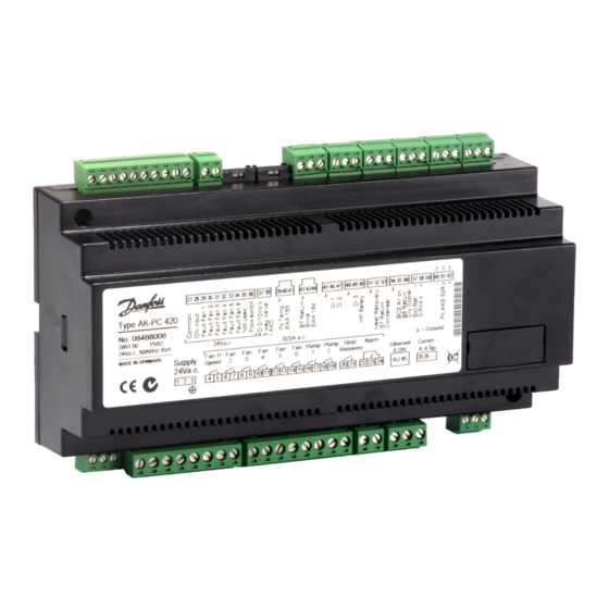
Page 16: Connections
27-30 24 V signal from the safety circuit fan 2 27-31 24 V signal from the safety circuit fan 3 If AK-PC 420 is used together with another control for compres- 27-32 24 V signal from the safety circuit fan 4 sors, e.g.:... -
Page 17: Data
Electronic controls are no substitute for normal, good engineering practice. Danfoss will not be responsible for any goods, or plant compo- nents, damaged as a result of the above defects. It is the installer's responsibility to check the installation thoroughly, and to fit the necessary safety devices. -
Page 18: Appendix - Reference And Regulation
“n04 Valve Xp” and “n05 valve Tn s”, and the fans are controlled via regula- one degree. For heat recovery the reference is changed to r64 Heat SP °C, and r30 is raised to 99.9°C tion parameters “n60 Fan Xp” and “n61 Fan Tn s”. Manual RS8EL402 © Danfoss 03-2010 AK-PC 420... - Page 19 The cutin and cutout of fans are shown in the drawing. “n04 Valve Xp” and the fans are controlled via proportional band “n60 If the fan capacity is controlled by speed regulation, the capacity will be indicated on the broken line. AK-PC 420 Manual RS8EL402 © Danfoss 03-2010...
- Page 20 Ref. min. = Sc3 + Min. tm K Danfoss can accept no responsibility for possible errors in catalogues, brochures and other printed material. Danfoss reserves the right to alter its products without notice. This also applies to products already on order provided that such alternations can be made without subsequential changes being necessary in specifications already agreed.
Need help?
Do you have a question about the AK-PC 420 and is the answer not in the manual?
Questions and answers