Advertisement
Advertisement
Table of Contents

Related Manuals for Danfoss AK-PC 551


Summary of Contents for Danfoss AK-PC 551
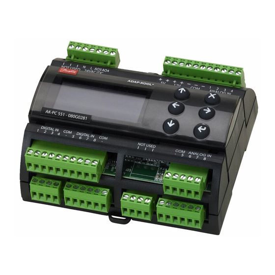
- Page 1 User Guide Capacity Controller AK-PC 551 ADAP-KOOL® Refrigeration Control System...
-
Page 2: Operation
The controller contains several languages. Select the preferred language at start-up. Data communication The controller has built-in modbus data communication, and it can be connected to an AK-SM 800 type system device. User Guide RS8GY302 © Danfoss 2015-06 AK-PC 551... -
Page 3: Suction Group
In this way, the total electrical load in the store is limited. The threshold value may not be set lower than the compressor’s lowest capacity step/”Start speed”. AK-PC 551 User Guide RS8GY302 © Danfoss 2015-06... - Page 4 If controlling a media temperature, the control sensor must be set to S7. This temperature sensor must be located in the desired medium. The Pc pressure transmitter must also be installed. It is used for high-pressure monitoring. User Guide RS8GY302 © Danfoss 2015-06 AK-PC 551...
-
Page 5: Safety Functions
Sd from a Copeland digital scroll, a Copeland stream or Bitzer CRII the capacity will be increased so that the compressor can cool down itself ). The compressors will be stopped if the temperature nears the set max. temperature value. AK-PC 551 User Guide RS8GY302 © Danfoss 2015-06... -
Page 6: Display Overview
By clicking the right arrow you can see these three displays: Active alarms Cleared Alarms Information on the controller When an alarm is sent from the controller, you must advance to this display to see the alarm text. User Guide RS8GY302 © Danfoss 2015-06 AK-PC 551... -
Page 7: Setup Overview
When the Plant type has None been selected, it will al- low several settings to be made. For example: Continue to the next menus. All settings are explained on the pages that follow. AK-PC 551 User Guide RS8GY302 © Danfoss 2015-06... - Page 8 • Severe alarm • All alarms (In the event of an alarm, the sound generator can be stopped by moving across the active alarm screen; see page 6) Suction A Control status Regulation status User Guide RS8GY302 © Danfoss 2015-06 AK-PC 551...
- Page 9 At start-up, the cooling system must have time to cool down before PI regulation takes over Min: 0 s Max: 300 s the regulation role and can cut in the next compressor. Fac: 120 s Set the time before the next compressor may be started here. AK-PC 551 User Guide RS8GY302 © Danfoss 2015-06...
- Page 10 Set the period time for the unloader valve (on time + off time) Fac: 20 s CRII Period time **: For CRII Min: 10 s Max: 20 s Set the period time for the unloader valve (on time + off time) Fac: 60 s User Guide RS8GY302 © Danfoss 2015-06 AK-PC 551...
- Page 11 Min: 1 min. Max: 60 min Set the forced Off-time during which the compressor must be off before it can be Fac: 4 min switched on again. The setting is to prevent incorrect operation. AK-PC 551 User Guide RS8GY302 © Danfoss 2015-06...
- Page 12 Min: -25°C (-1.0 bar) Max: 90°C (159 bar) Also set a value if regulating with a fluid reference (set point value used in the event of an Fac: 35°C (15.0 bar) outside temperature sensor error). User Guide RS8GY302 © Danfoss 2015-06 AK-PC 551...
- Page 13 Define whether a heat recovery cycle should be started with a signal on a DI input here. DI-demand • No: No function Yes / No • Yes: A DI input is reserved. When a signal is registered, the heat recovery function reference Fac: No will become active. AK-PC 551 User Guide RS8GY302 © Danfoss 2015-06...
- Page 14 When a sensor error has occurred, an O.K. signal must be registered within a specified Fac: 10 min. number of minutes before the controller resets the alarm. The regulation will be resumed as soon as the sensor signal is O.K. User Guide RS8GY302 © Danfoss 2015-06 AK-PC 551...
- Page 15 If you log out here without waiting for the time-out period to elapse, go to the overview display and hold down the “X” button for 3 seconds. Display contrast Adjust contrast Min: 0 Max: 100 Fac: 30 AK-PC 551 User Guide RS8GY302 © Danfoss 2015-06...
- Page 16 Select an input and continue on into the setting. In the final setting you will have be able to select which function you wish to connect to the input. User Guide RS8GY302 © Danfoss 2015-06 AK-PC 551...
- Page 17 Disable: Alarms set to this priority level will be cancelled. High pressure: Factory setting for the alarm can be seen on page 21. Compressor safety: Suction group B Low pressure: High pressure: Compressor safety: Condenser High pressure: Fan safety: AK-PC 551 User Guide RS8GY302 © Danfoss 2015-06...
- Page 18 20 to 35 display screens, depending on what is selected along the way. The selection will also result in a connection to a given input and output. You yourself will see this connection in the IO configuration menu. If applicable, see page 20. User Guide RS8GY302 © Danfoss 2015-06 AK-PC 551...
- Page 19 AK-PC 551 User Guide RS8GY302 © Danfoss 2015-06...
- Page 20 • Saux for general thermostat in “IO configuration”. Here is an example of 3 compressors and 3 fans: In this image you can see how many outputs and inputs your settings have provided. User Guide RS8GY302 © Danfoss 2015-06 AK-PC 551...
-
Page 21: Alarm List
If you have corrected the sensor error and want to perform a manual, forced removal of the alarm, go to the “Alarm detail display” Press and hold the “X” key for 2 seconds here. AK-PC 551 User Guide RS8GY302 © Danfoss 2015-06... - Page 22 9. Press the X key to return to the Bios menu 10. Select the “Application” menu and press Enter. The display will once again retrieve data from the controller. This process will take about 5 minutes. User Guide RS8GY302 © Danfoss 2015-06 AK-PC 551...
- Page 23 • Ratiometric: 10-90% of supply, AKS 32R • Signal: 1-5 V, AKS 32 Temperature sensor 0-20mA • Pt 1000 ohm, AKS 11 or AKS 21. 4-20mA AKS 33 • NTC 86K ohm @ 25°C, from digital scroll AK-PC 551 User Guide RS8GY302 © Danfoss 2015-06...
- Page 24 As a result, the evaporators will not be filled with fluid that can be led to a compressor when the regulation process restarts. One of the compressor control relays can be used for this function, or the function can be prompted via data communication. User Guide RS8GY302 © Danfoss 2015-06 AK-PC 551...
-
Page 25: External Display
24 V 080G0294 MMIGRS2 Display unit With buttons and display Wire for display unit, L = 1.5 m, 1 pcs. 080G0075 080G0076 Wire for display unit, L = 3 m, 1 pcs. AK-PC 551 User Guide RS8GY302 © Danfoss 2015-06... -
Page 26: Mounting Dimensions
Danfoss can accept no responsibility for possible errors in catalogues, brochures and other printed material. Danfoss reserves the right to alter its products without notice. This also applies to products already on order provided that such alternations can be made without subsequential changes being necessary in specifications already agreed.
Need help?
Do you have a question about the AK-PC 551 and is the answer not in the manual?
Questions and answers