Table of Contents
Advertisement
Quick Links
Advertisement
Chapters
Table of Contents

Related Manuals for Stanford Research Systems SR844


Summary of Contents for Stanford Research Systems SR844
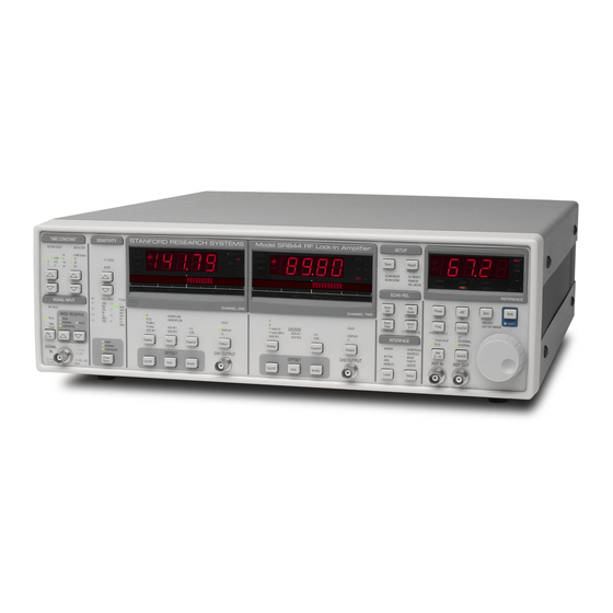
- Page 1 User’s Manual Model SR844 RF Lock-In Amplifier 1290-D Reamwood Avenue Sunnyvale, California 94089 Phone: (408) 744-9040 • Fax: (408) 744-9049 email: infor@thinkSRS.com • www.thinkSRS.com Copyright © 1997, 2007, 2013 by SRS, Inc. All Rights Reserved. Revision 2.9 (07/2016)
- Page 2 Certification Stanford Research Systems certifies that this product met its published specifications at the time of shipment. Stanford Research Systems further certifies that its calibration measurements are traceable to the United States National Institute of Standards and Technology (NIST). Warranty This Stanford Research Systems product is warranted against defects in materials and workmanship for a period of one (1) year from the date of shipment.
-
Page 3: Safety And Preparation For Use
This instrument may be damaged if operated with the LINE VOLTAGE SELECTOR set for the wrong AC line voltage or if the wrong fuse is installed. Line Voltage The SR844 operates from a 100V, 120V, 220V, or 240V nominal AC power source Selection having a line frequency of 50 or 60 Hz. - Page 4 Symbols that may be found on SRS products Symbol Description Alternating current Caution - risk of electric shock Frame or chassis terminal Caution - refer to accompanying documents Earth (ground) terminal Battery Fuse On (supply) Off (supply) SR844 RF Lock-In Amplifier...
-
Page 5: Table Of Contents
Inside the DSP 2-12 Analog Outputs and Scaling 2-15 What is Dynamic Reserve ? 2-17 Sources of Error 2-19 Using the SR844 as a Double Lock-In 2-22 Noise Measurements 2-23 Intrinsic (Random) Noise Sources 2-24 External Noise Sources 2-25 Chapter 3 Operation... - Page 6 Amplitude Response Phase Response Frequency Accuracy 5-11 Ref Out Amplitude 5-13 DC Outputs and Inputs 5-15 Input Noise 5-17 SR844 Performance Test Record 5-19 Chapter 6 Circuitry Service Circuit Board Locations Circuit Descriptions Parts Lists 6-25 Schematic Diagrams 6-80 SR844 RF Lock-In Amplifier...
-
Page 7: Specifications
Harmonic Detect Detect at 50 kHz ≤ 2×Reference ≤ 200 MHz. Phase Resolution 0.02 ° Absolute Phase Error ° < 50 MHz < 2.5 < 100 MHz < 5.0 ° < 200 MHz < 10.0 ° SR844 RF Lock-In Amplifier... - Page 8 The ratio input is normalized to 1 V and has a dynamic range > 100. Expand The CH1 and CH2 displays and outputs may be expanded by ×10 or ×100. SR844 RF Lock-In Amplifier...
- Page 9 Power 70 Watts, 100/120/220/240 VAC, 50/60 Hz. Dimensions 17" W x 5.25" H x 19.5" D Weight 23 lb. Warranty One year parts and labor on materials and workmanship. SR844 RF Lock-In Amplifier...
- Page 10 SR844 RF Lock-In Amplifier...
-
Page 11: Getting Started
Chapter 1 Getting Started The tutorials in this chapter are designed to acquaint the first time user with the SR844 RF Lock-In Amplifier. The functions and features of the SR844 are grouped together into several short tutorials. You may choose to do the tutorials selectively depending on your level of experience and your measurement needs. - Page 12 Getting Started SR844 RF Lock-In Amplifier...
-
Page 13: Quick Start
Quick Start Quick Start This section will lead you through the most basic setup and use of the SR844 RF lock-in amplifier. You must have selected the line voltage (page i) and connected AC power in order to proceed further. - Page 14 Check the readings on the front panel Press CH1 Display to select R [dBm]. The R[dBm] displays. display on CH1 should read +5.6 to +9.6 dBm. SR844 RF Lock-In Amplifier...
-
Page 15: The Basic Lock-In
SIGNAL IN with the BNC cable. square wave into 50 ) is within the unit’s measurement range (1 Vrms) so we can connect it directly to the input. The SR844 input impedance is Ω Ω Ω Ω Ω (shown by the 50... - Page 16 π x 0.5 Vpk x 1.19 or The detected amplitude is 4/ 0.759 Vpk. The SR844 reads the signal in units of Vrms (0.707 x Vpk) or 0.537 Vrms. The CH1 display may not read exactly 0.54 V for a number of reasons: •...
- Page 17 The indicated time constant should be 3, x1,s. The constant is 3 s. CH1 and CH2 displays remain nearly unchanged. Disconnect the cable at the SIGNAL IN The bargraph falls slowly. connector. Wait until the CH1 reading drops to zero. SR844 RF Lock-In Amplifier...
- Page 18 The high output bandwidth in this case requires that the outputs be taken from the CH1 or CH2 OUTPUT from the front panel and not from the displays. Press Slope/Oct DOWN until 12 dB is 12 dB/oct works well in most situations. selected. SR844 RF Lock-In Amplifier...
-
Page 19: X, Y, R, Θ Θ Θ Θ And Dbm
You will need a synthesized signal generator cable of providing 200 mVrms (0 dBm) Ω sine waves at 100 kHz into a 50 load (the DS335 from Stanford Research Systems will suffice), and BNC cables. Specifically you will display the lock-in outputs when measuring a signal that has a frequency close to, but not equal to, the internal reference frequency. - Page 20 CH2 now shows the signal phase . The phase is changing linearly with a rate equal to the frequency difference between the signal generator and the SR844. The readout and bargraph ramp linearly and ° ° smoothly from –180 to +180 (or vice-versa) once θ...
- Page 21 Change the signal generator frequency to 1.00 The SR844 UNLOCK error indicator comes on MHz. briefly, then goes off to indicate that the SR844 has locked to the new frequency. The new frequency should be correctly displayed in the Reference display.
-
Page 22: Outputs, Offsets And Expands
+ (1/5) + (1/7) + ... 1.19 π x 0.5 Vpk x 1.19 or The detected amplitude is 4/ 0.759 Vpk. The SR844 reads the signal in units of Vrms (0.707 x Vpk) or 0.537 Vrms. SR844 RF Lock-In Amplifier... - Page 23 The XYOffs indicator in the Channel 1 Display has turned on to indicate that the display quantity is affected by XY offsets. Offsets are useful for making relative measurements or to cancel the contribution from an unwanted phase coherent signal. In analog lock-ins, offsets SR844 RF Lock-In Amplifier...
- Page 24 1-14 Outputs, Offsets and Expands were generally used to remove DC output errors from the lock-in itself. The SR844 demodulator is digital and has no DC output errors, however, it does have some coherent pickup at high frequencies, which can be canceled using offsets.
- Page 25 Offsets add and subtract from the display. Expand increases the resolution of the display and the gain of the analog output. SR844 RF Lock-In Amplifier...
- Page 26 CH1 displayed quantity.) Press CH1 Offset Modify. The offset of the CH1 display quantity, R(V), is shown on the Reference display. The reading is in percent of full scale. SR844 RF Lock-In Amplifier...
- Page 27 Turn off X offset. This also turns off Y offset. The XYOffs indicators turn off and the displays show the original measurement of the REF OUT signal. This completes this exercise. For more information see Chapter 3, CH1 Display and Output. SR844 RF Lock-In Amplifier...
-
Page 28: Storing And Recalling Setups
1-18 Storing and Recalling Setups Storing and Recalling Setups The SR844 can store 9 complete instrument setups in non-volatile memory. Press Shift then Recall (PRESET) to restore This restores the SR844 to its factory presets. factory presets. The factory preset configuration is: 1 Vrms sensitivity. -
Page 29: Aux Outputs And Inputs
Aux Inputs to simulate external DC voltages which the lock-in can measure. Press Shift then Recall to restore factory This restores the SR844 to its factory presets. presets. Connect AUX OUT 1 on the rear panel to the The Aux Outputs can provide programmable DC DVM. - Page 30 The displays may be stored in the internal data buffers at a programmable sampling rate. This allows θ storage of not only the lock-in outputs (X, Y, R or ) but also the values of the AUX IN voltages. See Chapter 4, Data Storage, for more information. SR844 RF Lock-In Amplifier...
- Page 31 20 kHz High Pass Filter IF Sidebands 2-19 20 dB Gain Coherent Pickup 2-20 Reference Channel 2-10 Using the SR844 as a Double Lock-In 2-22 Auto-Threshold Comparator 2-10 Noise Measurements 2-23 Phase Locked Loop and Divider Chain 2-10 How Does a Lock-in Measure Noise ?
- Page 32 SR844 Basics SR844 RF Lock-In Amplifier...
-
Page 33: What Is A Lock-In Amplifier
The lock-in amplifier multiplies the signal by the reference V sin(ω ) using a mixer. (Note: The SR844 uses a more complicated reference signal for reasons discussed below, but the principle is the same.) The mixer generates the product of its two inputs as its output V (2–1) -
Page 34: Units
Lock-in amplifiers as a general rule measure the input signal in Volts rms. When the SR844 displays a magnitude of 1 V (rms), the sine component of the input signal at the reference frequency has an amplitude of 1 Vrms or 2.8 Vpk-pk. This is important to remember whenever the input signal is not a sine wave. -
Page 35: Volts Or Dbm
Volts or dBm ? The SR844 permits users to display some output quantities in either Vrms or dBm. The quantities that may be displayed in dBm are R (amplitude of the input signal) and Y- noise. Note that X and Y may only be displayed in Volts — they are the components of the input signal in rectangular coordinates and may be both positive and negative. -
Page 36: What About Dc Offset And Drift
The solution used in the SR844 is to chop the mixer reference signals. This means that the mixer reference signals reverse their polarity at the chop frequency. A signal at the reference frequency generates a mixer output that also changes sign at the chop frequency. - Page 37 It is not necessary to provide an external reference to the SR844. The SR844 contains a digital frequency synthesizer that may be used as an internal reference source. This is a convenient feature in those cases where an external generator is not available.
-
Page 38: The Functional Sr844
SR844 Basics The Functional SR844 The functional block diagram of the SR844 RF Lock-In Amplifier is shown below. A short description of each block follows . SR844 Block Diagram RF Signal Path 50 Ω 1 MΩ 200 MHz 20 dB... -
Page 39: Rf Signal Input Path
The path the input signal takes from the front panel input to the two mixers depends on the chosen input impedance and wide (RF) reserve. The SR844 accepts input signals in the range 25 kHz to 200 MHz, with signal levels up to 1 Vrms (+13 dBm). (The damage threshold is 5 V DC+AC.) -
Page 40: Reference Channel
Auto-Threshold Comparator The auto-threshold circuit detects the maximum and minimum voltages of the waveform and sets the threshold level to the mean of these two voltages. The SR844 uses the positive transitions through the threshold voltage as its phase reference. -
Page 41: If Section
The analog-to-digital converters (ADCs) digitize the IF outputs for the digital signal processor (DSP) for further processing. The sampling rate varies between 48–96 kHz. The sampling clock comes from the divider chain in the reference channel and is synchronous with the reference frequency. SR844 RF Lock-In Amplifier... -
Page 42: Inside The Dsp
2-12 SR844 Basics Inside the DSP Much of the signal processing in the SR844 occurs inside the Digital Signal Processor (DSP). Inside the DSP IF Demodulator ÷ X-IF R offset X offset 6, 12, 18, 24 Compute dB/oct Filter R and θ... -
Page 43: Offsets
In analog lock-ins, offsets were generally used to remove DC output errors from the mixer outputs. The SR844 demodulator is digital and has no DC output errors, however, it does have coherent pickup at high frequencies, which can be canceled using offsets. -
Page 44: R, Θ, Dbm Computation
DSP and the remote ports (GPIB and RS-232). The host processor receives the front panel output values from the DSP and displays them and sends the data to the remote ports. The host also computes X-noise and Y-noise from the X and Y data. SR844 RF Lock-In Amplifier... -
Page 45: Analog Outputs And Scaling
The SR844 considers 10 Vdc to be full scale for any output proportional to simply X, Y or R. Values of X, Y and R are always rms values. Noise is also measured in rms Volts and Xnoise and Ynoise are scaled the same as X and Y. -
Page 46: Display Scales
100 mV of output. If the output is expanded by 10, these small deviations are magnified by 10 and provide 1 V of output. The SR844 can expand the output by 10 or 100 provided the expanded output does not µ... -
Page 47: What Is Dynamic Reserve
Since the interfering signals see lots of gain, a relatively small interfering signal could cause an overload. SR844 RF Lock-In Amplifier... - Page 48 2-18 SR844 Basics Recognizing that different experimental situations call for different gain-allocation strategies, the SR844 provides multiple dynamic reserve modes separately for both the RF signal gain (before the mixer) and the IF gain (after the mixer). Wide Reserve or RF reserve, allocates the RF signal gain before the mixer. See Chapter 3, Signal Input, for a table of RF gain vs Wide Reserve.
-
Page 49: Sources Of Error
The detected amplitude is 4/ x peak x 1.2 or 1.53 x peak. The SR844 reads the signal in units of Vrms (0.707 x 1.53 x peak) or 1.08 x peak (Vrms). IF Sidebands ω... -
Page 50: Coherent Pickup
RF signal path. This is called coherent pickup. Since the pickup is phase coherent with the reference frequency it is detected by the SR844 as if it was a real signal input. Measuring signals which are smaller than the instrument’s own coherent pickup requires care and the use of offsets. - Page 51 Another source of coherent pickup is in the experimental setup itself. The signal and reference cables and grounds are very important, especially at higher reference frequencies. The X and Y offsets can be used to cancel the coherent pickup as long as the pickup remains stable during the experiment. SR844 RF Lock-In Amplifier...
-
Page 52: Using The Sr844 As A Double Lock-In
Or you could have the SR844 detect both the 100 MHz and 100 Hz signals as follows: put the 100 Hz reference signal into the SR844’s AUX IN 1 input, turn on ratio mode, and have the SR844 make the measurement for you directly, say with a 1 s time constant. -
Page 53: Noise Measurements
For more stable readings, use longer time constants. In the SR844 the X and Y noise are computed in the host processor; the MAD algorithm is used because it requires less computation and is a moving average. The X and Y data values are sampled (from the DSP) at a 512 Hz rate;... - Page 54 2-24 SR844 Basics settling time is required. If the sensitivity (or other measurement parameter) is changed, then the noise estimate will need to settle to the correct value. SR844 RF Lock-In Amplifier...
-
Page 55: Intrinsic (Random) Noise Sources
The ENBW is determined by the time constant and slope as shown previously. Ω The Johnson noise of a 50 input on the SR844 is simply (rms) = 0.91 nV × √ (ENBW) NOISE Shot Noise Electric current has noise due to the finite nature of the charge carriers. There is always some non-uniformity in the electron flow which generates noise in the current. -
Page 56: External Noise Sources
NOISE STRAY capacitance. This type of coupling is especially damaging since it is proportional to frequency and the SR844 operates at very high frequencies. ω For example, if the noise source is a computer clock line, /2π might be 33 MHz and might be 5 V/2. -
Page 57: Inductive Coupling
• Using magnetic shielding to prevent the magnetic field from crossing the area of the experiment. Resistive coupling or Ground Loops Currents flowing through ground connections can give rise to noise voltages. This is especially a problem with reference frequency ground currents. Signal Detector Source Noise Source SR844 RF Lock-In Amplifier... - Page 58 Not all sources of noise are electrical in origin. Mechanical noise can be translated into electrical noise by microphonic effects. Physical changes in the experiment or cables (due to vibrations, for example) can result in electrical noise at the lower end of the SR844’s operating frequency range.
- Page 59 Using Frequency Scans 3-35 Rear Panel Connectors Storing and Using Rel Values 3-36 Factory Preset Values Scan and Rel Example 3-39 Rels without Scan 3-40 Signal Input Auto Functions 3-41 Time Constants 3-11 Shift Functions 3-42 Sensitivity 3-13 SR844 RF Lock-In Amplifier...
- Page 60 Operation SR844 RF Lock-In Amplifier...
-
Page 61: Overview
Ref Out Power The power switch is on the rear panel. The SR844 is turned on by pushing the switch up. The serial number (5 digits) is shown on the CH1 and CH2 displays and the REFERENCE display shows the firmware version. The following internal tests are performed. -
Page 62: Keys
Simultaneous keypresses are reserved for a few test functions and are designated with a + sign, e.g. Local+Setup. Invalid keypresses cause the SR844 to produce an audible error tone. Key-Click On/Off Press TimeConstUp+TimeConstDown (both keys simultaneously) to toggle the key- click on and off. -
Page 63: Local Lockout
Display Off Operation Enter the Display Test mode as explained above. Press Phase until no LED’s are lit. The SR844 is still operating, output voltages are updated and the unit responds to interface ° commands. To change a setting press any key other than Phase ,+90... -
Page 64: Rear Panel Connectors
The reference out signal is phase coherent with the reference signal Ω internal to the SR844. It is a square wave, nominally 1 Vpp into 50 In external reference mode, this signal is phase-locked to the external reference input, while in internal mode it is derived from a frequency synthesizer and locked to an internal 20 MHz crystal oscillator. -
Page 65: Factory Preset Values
(approx. 0.3 mV). The input impedance is 1 M and the bandwidth is limited to about 3 kHz. The SR844 can report this voltage just like a digital voltmeter, or the voltage can be used to normalize the signal in ratio mode. -
Page 66: Signal Input
Refer to the Chapter 2, The Functional SR844, for more information. Ω Ω Sig Z-In This key selects the input impedance of the SR844 Signal Input, either 50 or 1 M The indicators above the key show the current selection. Ω... - Page 67 +20 dB +20 dB +20 dB +20 dB 10 µV +20 dB +20 dB +20 dB +20 dB +20 dB +20 dB 3 µV +20 dB +20 dB +20 dB +20 dB +20 dB +20 dB SR844 RF Lock-In Amplifier...
- Page 68 +20 dB +20 dB +20 dB +20 dB 300 nV +20 dB +20 dB +20 dB +20 dB +20 dB +20 dB 100 nV +20 dB +20 dB +20 dB +20 dB +20 dB +20 dB SR844 RF Lock-In Amplifier...
-
Page 69: Time Constants
The left hand UP/DOWN keys in this section select the output filter time constant. The µ Constant time constant of the SR844 may be set from 100 s to 30 ks in 1-3-10 steps. The time µ µ µ µ... - Page 70 In No Filter mode, the SR844 is acting more like a tuned receiver than a lock-in amplifier. No Filter mode is provided for those users who need the faster response time and are not concerned with limiting the detection bandwidth.
-
Page 71: Sensitivity
IF bandwidth (180 kHz). High reserve applies minimum IF Reserve gain preventing overloads before the DSP. Low Noise provides maximum IF gain and the best output signal to noise. Normal is somewhere in between. SR844 RF Lock-In Amplifier... - Page 72 (within ∼ ∼ 18 kHz with 6-24 dB/oct filtering). If IF OVLD is 180 kHz with No Filter and within on, try a higher close reserve or a larger sensitivity. SR844 RF Lock-In Amplifier...
-
Page 73: Ch1 Display And Output
This is the input signal noise at the reference frequency, and is derived from the X measurements. This quantity is discussed in greater detail in Chapter 2, Noise Measurements. AUX IN 1 This is the voltage applied to the rear panel AUX IN 1. SR844 RF Lock-In Amplifier... - Page 74 In analog lock-ins, offsets were generally used to remove DC output errors from the mixer outputs. The SR844 demodulator is digital and has no DC output errors, however, the SR844 does have coherent pickup at high frequencies, which can be canceled using offsets.
- Page 75 The Offset is displayed as a percentage of Full Scale. For R[dBm] full scale is 200 dBm regardless of the sensitivity. The knob may be used to modify the offset. Turn the Offset on to apply the displayed offset. SR844 RF Lock-In Amplifier...
- Page 76 Xnoise in ratio mode may be greater than the non-ratioed value. OVERFLOW The OVERFLOW indicator shows that the ratio Aux Input exceeds the input range ± 10.5 V). The ratioed outputs are no longer correct in this case. UNDER- FLOW SR844 RF Lock-In Amplifier...
- Page 77 10) or 1% ( 100) of full scale. Example: Suppose the X component of the input is 12.345 mV. The SR844 is set to 100 mV sensitivity with Offset, Ratio and Expand off. The CH1 display reads X=12.34 mV. The analog CH1 OUTPUT is 1.234 V (10 V is full scale). The offset is now turned On and set to –10%.
- Page 78 The OVLD indicator within the CH1 display indicates that the display has overloaded. ± The normal range of the display is 110% of full scale (without expand). Expand decreases the range of the display by 10 or 100. SR844 RF Lock-In Amplifier...
-
Page 79: Ch2 Display And Output
2, Noise Measurements. Ynoise This is the same quantity as above, converted into dBm. The dBm Ω [dBm] computation assumes a 50 load. AUX IN 2 This is the voltage applied to the rear panel AUX IN 2. SR844 RF Lock-In Amplifier... - Page 80 25.6 times per time constant. Offset User entered offsets can be added to X and Y. These offsets are added before taking θ ratios, output time-constant filtering, and computing R and SR844 RF Lock-In Amplifier...
- Page 81 In analog lock-ins, offsets were generally used to remove DC output errors from the mixer outputs. The SR844 demodulator is digital and has no DC output errors, however, it does have coherent pickup at high frequencies, which can be canceled using offsets.
- Page 82 Inputs, when in ratio mode, is from about 0.1 Volt to 10 Volts. Both positive and negative voltages are permitted. The SR844 has a single ratio mode that is common to both channels. The control for the ratio mode is the Ratio key in the Channel 1 Display section. The instrument’s ratio mode will be applied to the currently displayed Channel 2 quantity as shown by the AUX IN 1 and AUX IN 2 indicators.
- Page 83 10) or 1% ( 100) of full scale. Example: Suppose the Y component of the input is 12.345 mV. The SR844 is set to 100 mV sensitivity with Offset, Ratio and Expand off. The CH2 display reads Y=12.34 mV. The analog CH2 OUTPUT is 1.234 V (10 V is full scale). The offset is now turned On and set to –10%.
- Page 84 The OVLD indicator within the CH2 display indicates that the display has overloaded. ± The normal range of the display is 110% of full scale (without expand). Expand decreases the range of the display by 10 or 100. SR844 RF Lock-In Amplifier...
-
Page 85: Reference Section
Frequency and Reference Displays with extra precision. I.F. IF Frequency Only in Internal The IF (chop frequency) used Reference Mode in the SR844, provided for information. AuxOut AUX OUT 1, 2 The rear panel Aux Output voltages. CH1/CH2 Offset The offset (% f.s.) for the CH1 Offset Modify or CH2 display quantity. - Page 86 In INTERNAL reference mode, the internal reference frequency is displayed. The internal reference frequency is adjusted using the knob. The SR844 offers 3 digits of resolution in specifying the internal reference frequency, and 4 digits of accuracy. For example, frequencies of 1.23 and 1.24 MHz may be selected.
- Page 87 Reference Section 3-29 The SR844 is calibrated such that an input signal that is in phase with the rising edge of θ ° the External Reference input is measured as having X=R, Y=0 and when the ° Reference Phase is set to 0 .
- Page 88 Ω Ω Ω Ω 10 k || 40 pF. The reference signal should be 0 dBm (sine) or 0.7 Vpp (pulse) for proper locking. The SR844 will lock to other amplitudes with possible degradation in phase accuracy and jitter. OUT OF...
-
Page 89: Save And Recall
3-31 Save and Recall Nine setups of the SR844 may be saved in non-volatile memory (setup buffers 1-9). The stored setups include all front panel instrument settings, as well as the remote interface configurations. The Scan parameters used for manual scans are saved. -
Page 90: Interface
3-32 Interface Interface The SR844 can be interfaced to a host computer via RS232 or GPIB. The keys in this section configure the interface for proper operation with the host. These parameters must be set before attempting to interface the instrument to the host computer. - Page 91 Interface 3-33 LOCAL Remote interface commands can put the SR844 into either the Remote state or the Local Lockout state. It is possible to configure the unit over the remote interface so that the front panel is inoperative in these states. See in Chapter 4, Interface Commands, for information on how to do this.
-
Page 92: Scan And Rel
Overview Scans The SR844 offers the facility of doing a manual frequency scan covering up to 11 frequency points. This facility is available only in the Internal Reference mode. Frequency scans are a convenient method for making repeated measurements over a set of frequencies. For example, measurements of device noise or frequency response using REF OUT as the signal source. - Page 93 The number of points, N, is shown on the Reference Display. There is no Points indicator shown in the display. Use the knob to select from 2 to 11 steps. The number of points includes both the start and stop frequencies, so the SR844 RF Lock-In Amplifier...
- Page 94 Start = 100 kHz, Stop = 100 MHz, N = 4, which gives interpolated frequencies of 1 MHz and 10 MHz. The SR844 must be in Internal Reference mode to perform a scan. Start/Step has no effect unless the unit is in Internal Reference mode.
- Page 95 Store XY] discarded if they were stored with a measurement configuration which differs from the current one. The R[dBm]θ θ θ θ indicator turns on indicating that R θ Rel Values are stored for this scan frequency. SR844 RF Lock-In Amplifier...
- Page 96 REL indicators off. This does not affect REL MODE. configuration Start/Step This key is used to step through the scan frequencies. If REL MODE is on, stored Rel Configurations and Values (if previously stored) will be applied. SR844 RF Lock-In Amplifier...
- Page 97 In this example we will make transfer function measurements of a device–under–test, or DUT, using the SR844 REF OUT signal in Internal Reference mode. For this example, we assume that the DUT attenuates the REF OUT signal. We will make measurements at several frequencies using the Scan Mode. We will θ...
- Page 98 The Rel Configurations are indexed by frequency with a 1% tolerance band. Rels stored at 90.0MHz will be recalled whenever the frequency falls between 89.1MHz (-1%) and 90.9MHz (+1%). • You should familiarize yourself with the preceding sections before using the Rels without Scan. SR844 RF Lock-In Amplifier...
-
Page 99: Auto Functions
If the display is X or Y, Auto Offset is performed on both X and Y and turns on both X and Y offsets. This is true even if the other display is not displaying X or Y at the time. SR844 RF Lock-In Amplifier... -
Page 100: Shift Functions
IF frequency. Important! The SR844 covers the operating frequency range in octave bands. Users can check the IF frequency to determine whether the instrument is at the high end of an octave band or the low end of the next band. - Page 101 The 2F detection frequency is limited to 50 kHz to 200 MHz. This corresponds to a REF IN and REF OUT frequency range of 25 kHz to 100 MHz. The absolute phase in 2F mode is not specified. However, the relative phase accuracy generally applies. SR844 RF Lock-In Amplifier...
- Page 102 3-44 Shift Functions SR844 RF Lock-In Amplifier...
- Page 103 4-29 Status Reporting Commands 4-30 Status Register Definitions 4-31 Using Serial Poll 4-32 Using *STB? 4-33 Using Status Enable Registers 4-33 Service Requests (SRQ) 4-33 Example Program 4-34 Using Microsoft C with the GPIB interface 4-34 SR844 RF Lock-In Amplifier...
-
Page 104: Index Of Commands
(0) through 30 ks (17). OFSL(?){i} 4-13 Set (Query) the Time Constant Filter Slope to 6 (i=1), 12 (2), 18 (3), 24 (4) dB/oct, or NoFilter Mode (i=0). SETL(?) 4-14 Reset Elapsed Time counter to zero, return elapsed T.C.’s. SR844 RF Lock-In Amplifier... - Page 105 θ RRDY? i 4-21 Query Rels Ready XY (1) or R[dBm] (2) returns 0 (no) or 1 (yes). RCLR 4-21 Clear all stored Rel Values and Configurations. RMOD(?){i} 4-21 Query Rel/Lock on (1) or off (0). SR844 RF Lock-In Amplifier...
- Page 106 X and Y every sample during a scan over GPIB. STRD 4-28 Start a Scan after 0.5 s delay. Use with Fast Data Transfer mode. Interface *RST 4-29 Reset the SR844 to its default configuration. PRST 4-29 Power-On reset of SR844. *IDN? 4-29 Read the SR844 device identification string.
- Page 107 IF amplifier overloads. Any key–press or knob rotation. Time constant filter overloads. Power–on. Ref frequency changed by >1%. CH1 display or front panel ovld. CH2 display or front panel ovld. Aux input overflows. Aux input underflows. SR844 RF Lock-In Amplifier...
- Page 108 Index of Commands SR844 RF Lock-In Amplifier...
-
Page 109: Introduction
CTS/DTR hardware handshaking. The CTS signal (pin 5) is an output indicating that the SR844 is ready, while the DTR signal (pin 20) is an input that is used to control the SR844's data transmission. If desired, the handshake pins may be ignored and a simple 3 wire interface (pins 2, 3 and 7) may be used. -
Page 110: Command Format
OUTP? 1 <LF> Command Synchronization IFC (Interface Ready, bit 1) in the Serial Poll status signals that the SR844 is ready to receive and execute a command. When a command is received, this bit is cleared, indicating that command execution is in progress. No other commands will be processed until this command is completed. -
Page 111: Example Program
IFC bit set (since *STB? is itself a command). Since the SR844 processes one command at a time, status queries will not be processed until the previous operation is finished. Thus a response to a status query in itself signals that the previous command is finished. -
Page 112: Command Syntax
[ ] are not always required. Generally, parameters in { } are required to set a value in the SR844 and parameters in [ ] are optional in both set and query commands. Multiple parameters are separated by commas. Multiple commands may be sent on one command line by separating them with semicolons (;). -
Page 113: Reference And Phase Commands
The FRIQ? command queries the IF frequency. The returned value is an integer with units of Hz. The IF frequency will be in the range of approximately 2–3 kHz, for all time constants 1 ms and longer. The SR844 uses a higher IF, approximately 8–12 kHz, for faster time constants. PHAS(?){x} The PHAS command sets or queries the detection phase, in degrees, relative to the reference. -
Page 114: Signal Input Commands
Shift–WideReserveDown. AWRS automatically sets the Wide Reserve Mode of the instrument to the minimum reserve without overload. INPZ(?){i} The INPZ command sets or queries the Signal Input impedance. The parameter i Ω Ω selects 50 (i=0) or 1 M (i=1). SR844 RF Lock-In Amplifier... -
Page 115: Gain And Time Constant Commands
The OFSL command sets or queries the Time Constant Filter Slope. The parameter i selects 6 dB/oct (i=1), 12dB/oct (i=2), 18dB/oct (i=3), or 24 dB/oct (i=4). This command also sets the No Filter mode, with parameter i=0. SR844 RF Lock-In Amplifier... - Page 116 Elapsed Time as a real number, in units of the current Time Constant, since either the last SETL command or since the Settle... key was pressed. The SETL? query does not reset the Elapsed Time counter. SR844 RF Lock-In Amplifier...
- Page 117 –110 to +110 % of full scale R[V] –110 to +110 % of full scale R[dBm] –110 to +110 % of 200 dBm –110 to +110 % of full scale SR844 RF Lock-In Amplifier...
- Page 118 (see table above). The parameter i specifies No Expand (0), ×10 (1) or ×100 (2). θ The following quantities may be expanded: X, R[V], R[dBm], Xnoise, Y, , and Ynoise [Volts]. Specifying any other quantity in the DEXP command will result in an error. SR844 RF Lock-In Amplifier...
-
Page 119: Aux Input And Output Commands
The AUXO command sets or queries the Aux Output voltage. The parameter i (1 or 2) selects an Aux Output and is required. The parameter x is the output ≤ ≤ voltage (real number of Volts) and is limited to –10.500 10.500 . SR844 RF Lock-In Amplifier... -
Page 120: Setup Commands
The default mode is Override Remote On. In this mode the front panel is always active, regardless of the Remote or Local Lockout state. (A remote command will always put the SR844 into one of these states and illuminate the REMOTE indicator, except for LOCL0.) To lock-out the front panel, use the OVRM0 command. - Page 121 The shift keys are available by adding 64 to the corresponding standard key codes Settle Clear All θ Auto Sensitivity Store R[dBm] Auto Wide Reserve Auto Phase Auto Close Reserve -90° Preset Precise Freq Clear One 2F Mode On/Off Scan Off IF Frequency SR844 RF Lock-In Amplifier...
-
Page 122: Auto Functions
Both parameters ch and q are required. This command is equivalent to pressing the Auto Offset key. ch,q Quantity R[V] R[dBm] Important! Remember, Auto Offset X or Y performs Auto Offset on both X and Y. SR844 RF Lock-In Amplifier... -
Page 123: Scan And Rel Functions
(i=2). RRDY? i returns 0 (no Rel Values) or 1 (Rel Values stored). RCLR The RCLR command clears all stored Rel Values and Configurations. RMOD(?){i} The RMOD command sets and queries REL MODE Off (i=0) or On (i=1). SR844 RF Lock-In Amplifier... -
Page 124: Data Storage
Data Storage Introduction The SR844 can store up to 16383 points from both the Channel 1 and Channel 2 displays in an internal data buffer. The data buffer is not retained when the power is turned off. The data buffer is accessible only via the remote interfaces. - Page 125 Generally, the highest possible sample rate should be used given the desired storage time. The lock-in time constant and filter slope should be chosen to attenuate signals at frequencies higher than 1/2 the sample rate as much as possible. SR844 RF Lock-In Amplifier...
-
Page 126: Data Storage Commands
REST The REST command resets the data buffers. The REST command can be sent at any time – any storage in progress, paused or not, will be reset. This command will erase the data buffer! SR844 RF Lock-In Amplifier... -
Page 127: Data Transfer Commands
X, Y, Freq, and AUX IN 1. These values will be returned in a single string such as 0.9514E–3,–1.2271E-5,2.770E7,-3.219 The first value is X [V], the second is Y [V], the third is F [Hz] and the last is AUX IN 1 [V]. SR844 RF Lock-In Amplifier... - Page 128 0). A total of k bins are read (k 1). To read a single point, set k=1. Both j and k are required. If j+k exceeds the number of stored points (as returned by the SPTS? query), then an error occurs. SR844 RF Lock-In Amplifier...
- Page 129 = mantissa × 2 [exponent – 124] The data within the SR844 is stored in this format, so data transfers using this format is faster than IEEE floating point format. If transfer speed is important, then the TRCL? command should be used.
- Page 130 At fast sample rates, it is important that the receiving interface be able to keep up. If the SR844 finds that the GPIB interface is not ready to receive a point, then the fast transfer mode is turned off and GPB bit in the Error Status Register is set.
-
Page 131: Interface Commands
Local key which returns the SR844 to the Local state. In the Local Lockout state the entire front panel is locked out, including the Local key. -
Page 132: Status Reporting Commands
(0–65535). The LIAEi,j command sets bit i (0–15) to j (0 or 1). The LIAE? command queries the value (0–65535) of the LIA Status Enable register. The LIAE?i command queries the value (0 or 1) of bit i. SR844 RF Lock-In Amplifier... -
Page 133: Status Register Definitions
Status Registers 4-31 Status Register Definitions The SR844 reports on its status by means of four status registers: the Serial Poll Status, the Standard Event Status, the LIA Status and the Error Status. The status bits are set to 1 when an event has occurred or a state is present, as described in the tables below. - Page 134 Except for SRQ, a bit in the Serial Poll Status register is not cleared by serial polling. When reading the status using a serial poll, the SRQ bit signals that the SR844 is requesting service. The SRQ bit will be set (1) the first time the SR844 is polled following a service request.
- Page 135 SRQ, performs a serial poll to clear the SRQ, does something to try to remedy the situation (change gain, experimental parameters, etc.) and then clears the RSV status bit by reading the LIA Status register. A subsequent RSV overload will then generate another SRQ. SR844 RF Lock-In Amplifier...
-
Page 136: Example Program
To configure the SR844, the GPIB address must be set with the Setup key. The default address is 8; use this address unless a conflict occurs with other instruments in your system. The SR844 will be set to GPIB address 8 whenever a reset is performed (power on with the Setup key down). - Page 137 // To use another interface card, modify the GPIB subroutines // where indicated. // The SR844 is assumed to be at address 8 (default). // Link this object file with ieee488.lib provided by CEC // (or the library for your GPIB card).
- Page 138 (void) { // ******************************************************************* // You can see the commands received by the SR844 using the [Setup] key // to show the receive queue on the displays. The hex values of the received // characters will be shown.
- Page 139 // of the desired points at once // to avoid missing data between transfers. // Fast mode will abort if the SR844 finds the host not ready to receive data. TxSr844("PAUS; FAST0"); // Pause the data storage, turn off FAST mode settimeout (5000);...
- Page 140 TxGpib (sr844,cmd); // Send cmd and don't wait for IFC ready! transmit ("MLA TALK 8", &status); // Make sr844 the talker rarray ((char *)rfBuf, nPts*4, &nCount, &status); // Read directly into a FLOAT array rfBuf, 4 bytes per point if ( nCount != nPts*4 ) { printf ("\nERROR: expected %d bytes, received %d bytes",nPts*4,nCount);...
- Page 141 (i=0; i<10; i++) { sprintf (cmd, "TRCA?1,%d,1", i); // (CH1, starting with bin i, 1 point) GetSr844 (cmd); // Get string from SR844 strcpy (rAscBuf[i], recv); // Copy to string array rAscBuf sprintf (cmd, "TRCA?2,%d,1", i); // (CH2, starting with bin i, 1 point) GetSr844 (cmd);...
- Page 142 (recv, temp); // Set global receive string // ************************************************************************ void WaitIFC (void) { // Serial poll the SR844 until IFC (bit 1) is set (command done). // Modify for your GPIB interface. char stb; do {spoll (sr844,&stb,&status);} while (!(stb&2));...
- Page 143 // channel 2 mant = pLiaBuf[2*index]; // First comes the mantissa (16 bits) = pLiaBuf[2*index+1] - 124; // Then the binary exponent (16 bits) // offset by 124 = (double) mant * pow(2.0,(double) exp); return (val); // ************************************************************************ SR844 RF Lock-In Amplifier...
- Page 144 4-42 Example Program SR844 RF Lock-In Amplifier...
- Page 145 If A Test Fails 1. Self Tests 2. Amplitude Response 3. Phase Response 4. Frequency Accuracy 5-11 5. Ref Out Amplitude 5-13 6. DC Outputs and Inputs 5-15 7. Input Noise 5-17 SR844 Performance Test Record 5-19 SR844 RF Lock-In Amplifier...
- Page 146 Performance Tests SR844 RF Lock-In Amplifier...
-
Page 147: Getting Ready
The self-test does not require any warm-up period. Test Record Make a copy of the SR844 Performance Test Record at the end of this chapter. Fill in the results of the tests on this record. This record will allow you to determine whether the tests pass or fail, and also to preserve a record of the tests. -
Page 148: Front Panel Display Test
If the test continues to fail, contact Stanford Research Systems for instructions. Make sure you have the unit’s serial number and firmware revision code in hand. Have the test record with you also. -
Page 149: Self Tests
Setup No external setup is required for this test. Procedure 1) Turn the SR844 power switch off. Then turn the unit on while holding down the Setup key. Check the results of the DATA, BATT, PROG and DSP tests. DATA Performs a read/write test to the processor RAM. - Page 150 Performance Tests SR844 RF Lock-In Amplifier...
-
Page 151: Amplitude Response
Instead, this test is designed to use a simpler procedure which, if passed, verifies the functionality of the SR844. If the unit passes this test, then it is very probable that the unit meets its stated accuracy. This test is not intended to verify the accuracy of the SR844. - Page 152 200 MHz 3.1) Set the RF synthesizer to the frequency in the table. 3.2) Wait for the SR844 UNLOCK indicator to turn off. 3.3) Wait for the CH1 reading to stabilize. Record the CH1 reading (dBm). 4) Add one 20 dB attenuator at the SIGNAL IN. The total attenuation at the SIGNAL IN is now -23 dB.
-
Page 153: Phase Response
Instead, this test is designed to use a simpler procedure which, if passed, verifies the functionality of the SR844. If the unit passes this test, then it is very probable that the unit meets its stated accuracy. This test is not intended to verify the accuracy of the SR844. - Page 154 100 MHz 3.1) Set the RF synthesizer to the frequency in the table. 3.2) Wait for the SR844 UNLOCK indicator to turn off. 3.3) Wait for the CH2 reading to stabilize. Record the CH2 reading (degrees). 4) This completes the phase response test. Enter the results of this test into the test record at the end of this chapter.
-
Page 155: Frequency Accuracy
Performance Tests 5-11 4. Frequency Accuracy This test measures the frequency accuracy of the SR844. This tests the accuracy of the frequency counter inside the unit. The counter is used only in External Reference mode. Setup We will use the RF synthesizer (Marconi 2023 or equivalent) to provide the external reference signal. - Page 156 5-12 Performance Tests SR844 RF Lock-In Amplifier...
-
Page 157: Ref Out Amplitude
This test measures the amplitude and frequency response of the front panel REF OUT signal. Setup We will use the SR844 to measure the REF OUT signal amplitude. Connect the REF OUT to the SIGNAL Ω IN with a cable. The REF OUT signal is nominally a square wave with amplitude 1.0 Vpp into 50 . - Page 158 5-14 Performance Tests SR844 RF Lock-In Amplifier...
-
Page 159: Dc Outputs And Inputs
Performance Tests 5-15 6. DC Outputs and Inputs This test measures the DC accuracy of the DC outputs and inputs of the SR844. Setup We will use the digital voltmeter (DVM) to measure the DC outputs of the lock-in. Then we will use one of the outputs to generate a voltage to measure on the DC inputs. - Page 160 Record the value of AUX IN 1 (or AUX IN 2) from the CH1 (or CH2) display. 6) This completes the DC outputs and inputs test. Enter the results of this test in the test record at the end of the Chapter. SR844 RF Lock-In Amplifier...
-
Page 161: Input Noise
Performance Tests 5-17 7. Input Noise This test measures the SR844 input noise. Setup Ω Connect a 50 termination to the signal input. Procedure 1) Press Shift then Recall to restore the factory preset instrument settings. 2) Press the keys in the following sequence: Sensitivity Down until the sensitivity is 300 nV. - Page 162 5-18 Performance Tests SR844 RF Lock-In Amplifier...
-
Page 163: Sr844 Performance Test Record
SR844 Test Record 5-19 SR844 Performance Test Record Serial Number: Tested By: Firmware Revision: Date: Equipment Used: 1. Self Tests Test Pass Fail Data Batt Prog 2. Amplitude Response Sensitivity Frequency Lower Limit CH1 Reading (dBm) Upper Limit 300 mV 100 kHz -2.0 dBm... - Page 164 5-20 SR844 Test Record 3. Phase Response Sensitivity Frequency Lower Limit CH2 Reading (deg) Upper Limit ° ° 300 mV 100 kHz -6.0 +6.0 ° ° 300 kHz -6.0 +6.0 ° ° 1 MHz -6.0 +6.0 ° ° 3 MHz -6.0...
- Page 165 SR844 Test Record 5-21 6. DC Outputs and Inputs (continued) Output Voltage Lower Limit DVM Reading (V) Upper Limit AUX OUT 1 -10.000 V -10.010 V -9.990 V -5.000 V -5.010 V -4.990 V 0.000 V -0.005 V 0.005 V +5.000 V...
- Page 166 5-22 SR844 Test Record SR844 RF Lock-In Amplifier...
- Page 167 Signal Input (84SIG) Board 6-47 Mixer (84CMX) Board 6-51 IF Amplifier (84IFN) Board 6-55 Reference (84XRF) Board 6-64 Divider Chain (84DVC) Board 6-70 Digital Signal Processor (84DSP) Board 6-76 Final Assembly and Miscellaneous 6-79 Schematic Diagrams 6-80 SR844 RF Lock-In Amplifier...
- Page 168 Circuitry, Parts Lists and Schematics SR844 RF Lock-In Amplifier...
-
Page 169: Service
Do not install substitute parts or perform any unauthorized modifications to this instrument. For warranty service or repair, this product must be returned to a Stanford Research Systems authorized service facility. Contact Stanford Research Systems or an authorized representative before returning this product for repair. SR844 RF Lock-In Amplifier... -
Page 170: Circuit Board Locations
Supply Board Motherboard Display Board Keypad Board Circuit Boards The SR844 has five main printed circuit boards shown above. • The CPU/Power Supply board (844C) contains the host processor, interfaces and power supply. • The Keypad board (844K) holds the front panel indicators and keypad. - Page 171 This board is mounted on the bottom of the Motherboard. These boards overlap in some cases. Do not attempt to remove a daughter board until all boards which are above it are removed. The locations are shown below. Motherboard Top View SR844 RF Lock-In Amplifier...
-
Page 172: Circuit Descriptions
Power Supplies CPU–1... CPU–8: CPU System The host processor in the SR844 is an 80C186 microprocessor (U101) running at 12 MHz. This processor runs the front panel interfaces (keypad, display and knob), controls the instrument settings, and runs the remote interfaces (GPIB and RS-232). In addition the ‘186 performs numerous instrument calculations, such as computing calibration... - Page 173 U4 generates +5V for the instrument, ie the motherboard and boards mounted on the motherboard. U10 generates +8V for the instrument. U5 generates -7.7V for the instrument (primarily the ECL circuitry). U6 and U8 generate ±12V for SR844 RF Lock-In Amplifier...
-
Page 174: 844S: Display Board
Q2 (U9.18) is high, the corresponding transistor in U2 is turned on through N5.2. The collector of that transistor sinks current from line LED1 through the LED at row #1 and the currently active column. N9.2 is a current-limiting resistor. The other LED rows are similar. SR844 RF Lock-In Amplifier... -
Page 175: 844K: Keypad Board
For the TTL output, power and signals from J876 are wired to the daughter card attached to J877. The TTL output from the daughter card is connected to the rear panel BNC out J874. Note that on this board, the ground for the TTL output circuitry is not connected SR844 RF Lock-In Amplifier... -
Page 176: 84Mbd: Motherboard
Power supplies are decoupled from each other with capacitors and either beads, inductors or resistors. Separate circuit sections generally have independently regulated power. FR47 is a small surface-mount bead with 47Ω impedance at 100 MHz, FR95 is a bigger surface-mount bead with 95Ω impedance at 100 MHz. SR844 RF Lock-In Amplifier... - Page 177 Platform Interface after filtering; this signal goes low when the synthesizer is not phase- locked. The 20 MHz clock signal from U821 is buffered by U822A and attenuated by R823/C823. This signal is sent to 84DSP for use as the DSP clock. SR844 RF Lock-In Amplifier...
-
Page 178: 84Sig: Signal Input Board
6-12 Circuit Descriptions MRNGS: Range Select The SR844 operates in 13 octave ranges, from 25 kHz to 200 MHz. The ranges and the associated bit values are defined in a table in the description of 84DVC below. In internal reference mode, the host ‘186 processor knows what the instrument frequency and range should be and writes the range to the up/down counter U849 directly. -
Page 179: 84Cmx: Chop And Mix Board
SI0–SI2 come from. 84CMX: Chop and Mix Board The 84CMX board is located midway across the front of the instrument. It contains the Chop and Mix sections. Document Number Sheet Schematic CMXM Mixers CMXC Chop Circuit SR844 RF Lock-In Amplifier... - Page 180 I.F. signals, MIXX and MIXY for the In-Phase and Quadrature channels respectively. The operation of the In-Phase channel X mixer is described below; the operation of the Quadrature or Y channel is identical. SR844 RF Lock-In Amplifier...
-
Page 181: 84Ifn: I.f. And Noise Board
GND.X, the ground on 84CMX to which MIX.X is referenced. U400 is a differential amplifier with ×4 gain that converts the differential inputs to a single-ended signal referenced to local ground and also boosts the signal above the noise level of succeeding SR844 RF Lock-In Amplifier... - Page 182 ±2.5 V. The comparator outputs OVLD.X and OVLD.Y are TTL levels that go low when the A-to-D is overloaded. The 2.5 V thresholds are generated from the A-to-D RefOut of 2.75 V by op amps U479A,B. SR844 RF Lock-In Amplifier...
-
Page 183: 84Xrf: External Reference Board
ECL square wave. R213 is the optional 50Ω termination, which is switched into the circuit when relay S210 is closed. The coil for S210 is driven by Q210, whose input -REF50 comes from the SR844 RF Lock-In Amplifier... - Page 184 U310 is configured as a differential amplifier with ×10 gain. The idea is that when the circuit is phase-locked, both U and D are at ECL low and the diff amp output U310.6 is nominally zero. When unlocked, any activity on U or D causes U310.6 to deviate from SR844 RF Lock-In Amplifier...
- Page 185 The loop filter output U344.6 is the VCO tuning voltage VTUNE; it goes to the VCO. In addition, a copy equal to half the tuning voltage, VTUN2, is generated by U345 and is SR844 RF Lock-In Amplifier...
-
Page 186: 84Dvc: Divider Chain Board
84DVC: Divider Chain Board The 84DVC board is mounted just above the right rear portion of the motherboard. This board contains the divider chain. Since the SR844 operates synchronously, all instrument operations are clocked by signals derived from the reference frequency. The divider chain takes the VCO output (200 –... - Page 187 The low-frequency inputs to U618 come from U643 and TTL multiplexer U649. The signals are converted from TTL to ECL levels using resistor networks R654/R674/R694 and R648/R668/R688. Similarly the low-frequency inputs to U619 come from U643 and TTL multiplexer U645. SR844 RF Lock-In Amplifier...
-
Page 188: 84Dsp: Digital Signal Processing Board
DSP uses the correct demodulation waveform. Pin PC8 (U900.33) is connected to the Timer input U900.39 enabling the DSP timer to make measurements of the Data Sampling period, and SR844 RF Lock-In Amplifier... - Page 189 47µs. The filtered output is amplified by U915A so as to provide outputs spanning ±10V. The channel 1 circuitry is identical. The outputs go to the rear panel BNCs via connector J2 on the motherboard. SR844 RF Lock-In Amplifier...
- Page 190 R928 and Z923 filter the Channel 2 (Y) output with a 4.7µs time constant. The filtered output is amplified by U915C so as to provide outputs spanning ±10V. The outputs go to the front panel via connectors J5 (X) and J6 (Y) on the motherboard. SR844 RF Lock-In Amplifier...
-
Page 191: Parts Lists
Parts Lists 6-25 Parts Lists Parts lists for all of the circuit boards are listed in the following sections. Schematic diagrams follow the parts lists at the end of this manual. SR844 RF Lock-In Amplifier... -
Page 192: Cpu And Power Supply (844C) Board
.1U AXIAL Capacitor, Ceramic, 50V,+80/-20% Z5U AX C 1015 5-00225-548 .1U AXIAL Capacitor, Ceramic, 50V,+80/-20% Z5U AX C 1016 5-00225-548 .1U AXIAL Capacitor, Ceramic, 50V,+80/-20% Z5U AX C 1017 5-00225-548 .1U AXIAL Capacitor, Ceramic, 50V,+80/-20% Z5U AX SR844 RF Lock-In Amplifier... - Page 193 Connector, IEEE488, Standard, R/A, Femal JP903 1-00016-160 RS232 25 PIN D Connector, D-Sub, Right Angle PC, Female JP1000 1-00170-130 26 PIN ELH Connector, Male 6-00055-630 FB43-1801 Ferrite Beads 6-00055-630 FB43-1801 Ferrite Beads 6-00055-630 FB43-1801 Ferrite Beads 6-00055-630 FB43-1801 Ferrite Beads SR844 RF Lock-In Amplifier...
- Page 194 Resistor, Metal Film, 1/8W, 1%, 50PPM R 713 4-00056-401 Resistor, Carbon Film, 1/4W, 5% R 901 4-00034-401 Resistor, Carbon Film, 1/4W, 5% R 911 4-00022-401 1.0M Resistor, Carbon Film, 1/4W, 5% R 912 4-00062-401 Resistor, Carbon Film, 1/4W, 5% SR844 RF Lock-In Amplifier...
- Page 195 Integrated Circuit (Thru-hole Pkg) U 906 3-00109-340 MC1488 Integrated Circuit (Thru-hole Pkg) X 101 6-00068-620 24.000 MHZ Crystal X 902 6-00037-620 3.6864 MHZ Crystal 0-00158-000 60MM 24V Hardware, Misc. 0-00186-021 6-32X1-3/8PP Screw, Panhead Phillips 0-00187-021 4-40X1/4PP Screw, Panhead Phillips SR844 RF Lock-In Amplifier...
- Page 196 #8 X 1/16 Washer, nylon 0-00316-003 PLTFM-28 Insulators 0-00477-021 8-32X1/2 Screw, Panhead Phillips 0-00772-000 1.5" WIRE Hardware, Misc. 1-00087-131 2 PIN JUMPER Connector, Female 5-00262-548 .01U AXIAL Capacitor, Ceramic, 50V,+80/-20% Z5U AX 7-00501-720 SR830-8 Fabricated Part SR844 RF Lock-In Amplifier...
- Page 197 Cap, Monolythic Ceramic, 50V, 20%, Z5U C 894 5-00134-529 100P Cap, Monolythic Ceramic, 50V, 20%, Z5U 3-00013-306 LED, Rectangular 3-00013-306 LED, Rectangular 3-00013-306 LED, Rectangular 3-00175-306 YELLOW LED, Rectangular 3-00175-306 YELLOW LED, Rectangular 3-00175-306 YELLOW LED, Rectangular SR844 RF Lock-In Amplifier...
- Page 198 LED, Subminiature D 117 3-00575-311 GREEN MINI LED, Subminiature D 118 3-00575-311 GREEN MINI LED, Subminiature D 119 3-00575-311 GREEN MINI LED, Subminiature D 120 3-00575-311 GREEN MINI LED, Subminiature D 121 3-00575-311 GREEN MINI LED, Subminiature SR844 RF Lock-In Amplifier...
- Page 199 LED, Subminiature D 622 3-00575-311 GREEN MINI LED, Subminiature D 623 3-00575-311 GREEN MINI LED, Subminiature D 626 3-00769-311 YELLOW MINI LED, Subminiature D 716 3-00576-311 RED MINI LED, Subminiature D 717 3-00575-311 GREEN MINI LED, Subminiature SR844 RF Lock-In Amplifier...
- Page 200 Resistor Network, DIP, 1/4W,2%,8 Ind 4-00835-420 47X8 Resistor Network, DIP, 1/4W,2%,8 Ind 4-00468-420 300X8 Resistor Network, DIP, 1/4W,2%,8 Ind 4-00468-420 300X8 Resistor Network, DIP, 1/4W,2%,8 Ind 4-00468-420 300X8 Resistor Network, DIP, 1/4W,2%,8 Ind 4-00468-420 300X8 Resistor Network, DIP, 1/4W,2%,8 Ind SR844 RF Lock-In Amplifier...
- Page 201 Integrated Circuit (Thru-hole Pkg) U 28 3-00288-340 HDSP-H101 Integrated Circuit (Thru-hole Pkg) U 870 3-00781-360 NJM360 Integrated Circuit (Surface Mount Pkg) U 871 3-00781-360 NJM360 Integrated Circuit (Surface Mount Pkg) U 872 3-00751-360 74HC574 Integrated Circuit (Surface Mount Pkg) SR844 RF Lock-In Amplifier...
- Page 202 Cable Assembly, Custom 1-00344-130 3 PIN SI ZW Connector, Male 1-00345-130 3 PIN SI TLW Connector, Male 1-00347-169 SR844 3" COAX Cable Assembly, Custom 2-00034-220 ENA1J-B20 SOFTPOT 4-00681-436 SG240 Thermistor, ICL (Inrush Current Limiter) 6-00004-611 1A 3AG Fuse SR844 RF Lock-In Amplifier...
- Page 203 Fabricated Part 9-00267-917 GENERIC Product Labels Z 872 5-00315-527 .1UF Capacitor, Ceramic SMT1206, 50V, 20% Z5U Z 873 5-00315-527 .1UF Capacitor, Ceramic SMT1206, 50V, 20% Z5U Z 874 5-00315-527 .1UF Capacitor, Ceramic SMT1206, 50V, 20% Z5U SR844 RF Lock-In Amplifier...
- Page 204 Cap, Tantalum, SMT (all case sizes) F 62 5-00318-569 2.2U/T35 Cap, Tantalum, SMT (all case sizes) F 63 5-00318-569 2.2U/T35 Cap, Tantalum, SMT (all case sizes) F 64 5-00318-569 2.2U/T35 Cap, Tantalum, SMT (all case sizes) SR844 RF Lock-In Amplifier...
- Page 205 J 40 1-00303-131 8 PIN DIF CES Connector, Female J 41 1-00303-131 8 PIN DIF CES Connector, Female J 42 1-00304-131 10 PIN DIF CES Connector, Female J 43 1-00302-131 6 PIN DIF CES Connector, Female SR844 RF Lock-In Amplifier...
- Page 206 Ferrite bead, SMT L 60 6-00236-631 FR47 Ferrite bead, SMT L 61 6-00236-631 FR47 Ferrite bead, SMT L 64 6-00236-631 FR47 Ferrite bead, SMT L 65 6-00237-631 FR95 Ferrite bead, SMT L 67 6-00237-631 FR95 Ferrite bead, SMT SR844 RF Lock-In Amplifier...
- Page 207 Thick Film, 5%, 200 ppm, Chip Resistor R 42 4-01407-461 Thick Film, 5%, 200 ppm, Chip Resistor R 46 4-01430-461 Thick Film, 5%, 200 ppm, Chip Resistor R 54 4-01419-461 Thick Film, 5%, 200 ppm, Chip Resistor SR844 RF Lock-In Amplifier...
- Page 208 Thin Film, 1%, 50 ppm, MELF Resistor R 813 4-01181-462 4.64K Thin Film, 1%, 50 ppm, MELF Resistor R 814 4-01181-462 4.64K Thin Film, 1%, 50 ppm, MELF Resistor R 815 4-01181-462 4.64K Thin Film, 1%, 50 ppm, MELF Resistor SR844 RF Lock-In Amplifier...
- Page 209 U 805 3-00663-360 74HC08 Integrated Circuit (Surface Mount Pkg) U 807 3-00750-360 74HC573 Integrated Circuit (Surface Mount Pkg) U 808 3-00750-360 74HC573 Integrated Circuit (Surface Mount Pkg) U 809 3-00750-360 74HC573 Integrated Circuit (Surface Mount Pkg) SR844 RF Lock-In Amplifier...
- Page 210 Capacitor, Ceramic SMT1206, 50V, 20% Z5U Z 23 5-00315-527 .1UF Capacitor, Ceramic SMT1206, 50V, 20% Z5U Z 24 5-00315-527 .1UF Capacitor, Ceramic SMT1206, 50V, 20% Z5U Z 25 5-00315-527 .1UF Capacitor, Ceramic SMT1206, 50V, 20% Z5U SR844 RF Lock-In Amplifier...
- Page 211 Capacitor, Ceramic SMT1206, 50V, 20% Z5U Z 801 5-00315-527 .1UF Capacitor, Ceramic SMT1206, 50V, 20% Z5U Z 802 5-00315-527 .1UF Capacitor, Ceramic SMT1206, 50V, 20% Z5U Z 803 5-00315-527 .1UF Capacitor, Ceramic SMT1206, 50V, 20% Z5U SR844 RF Lock-In Amplifier...
- Page 212 Capacitor, Ceramic SMT1206, 50V, 20% Z5U Z 851 5-00315-527 .1UF Capacitor, Ceramic SMT1206, 50V, 20% Z5U Z 853 5-00315-527 .1UF Capacitor, Ceramic SMT1206, 50V, 20% Z5U Z 854 5-00315-527 .1UF Capacitor, Ceramic SMT1206, 50V, 20% Z5U SR844 RF Lock-In Amplifier...
- Page 213 2.2U/T35 Cap, Tantalum, SMT (all case sizes) F 196 5-00318-569 2.2U/T35 Cap, Tantalum, SMT (all case sizes) J 10 1-00293-130 6 PIN DI ZW 08 Connector, Male J 11 1-00330-130 8 PIN DIF CLT Connector, Male SR844 RF Lock-In Amplifier...
- Page 214 Thin Film, 1%, 50 ppm, MELF Resistor R 126 4-01084-462 Thin Film, 1%, 50 ppm, MELF Resistor R 128 4-01407-461 Thick Film, 5%, 200 ppm, Chip Resistor R 140 4-01001-462 61.9 Thin Film, 1%, 50 ppm, MELF Resistor SR844 RF Lock-In Amplifier...
- Page 215 Capacitor, Ceramic SMT1206, 50V, 20% Z5U Z 102 5-00315-527 .1UF Capacitor, Ceramic SMT1206, 50V, 20% Z5U Z 114 5-00315-527 .1UF Capacitor, Ceramic SMT1206, 50V, 20% Z5U Z 120 5-00315-527 .1UF Capacitor, Ceramic SMT1206, 50V, 20% Z5U SR844 RF Lock-In Amplifier...
- Page 216 Capacitor, Ceramic SMT1206, 50V, 20% Z5U Z 191 5-00315-527 .1UF Capacitor, Ceramic SMT1206, 50V, 20% Z5U Z 194 5-00315-527 .1UF Capacitor, Ceramic SMT1206, 50V, 20% Z5U Z 196 5-00315-527 .1UF Capacitor, Ceramic SMT1206, 50V, 20% Z5U SR844 RF Lock-In Amplifier...
- Page 217 8 PIN DI MTLW Connector, Male J 731 1-00329-131 3 PIN SIF - CES Connector, Female J 732 1-00329-131 3 PIN SIF - CES Connector, Female J 733 1-00329-131 3 PIN SIF - CES Connector, Female SR844 RF Lock-In Amplifier...
- Page 218 4-01053-462 Thin Film, 1%, 50 ppm, MELF Resistor R 792 4-01084-462 Thin Film, 1%, 50 ppm, MELF Resistor T 709 6-00055-630 FB43-1801 Ferrite Beads T 710 6-00055-630 FB43-1801 Ferrite Beads T 740 6-00055-630 FB43-1801 Ferrite Beads SR844 RF Lock-In Amplifier...
- Page 219 4-00993-462 51.1 Thin Film, 1%, 50 ppm, MELF Resistor Y 764 4-00993-462 51.1 Thin Film, 1%, 50 ppm, MELF Resistor Y 769 4-00993-462 51.1 Thin Film, 1%, 50 ppm, MELF Resistor 0-00478-055 1.5"X#30 BLK Wire, Other SR844 RF Lock-In Amplifier...
- Page 220 Capacitor, Ceramic SMT1206, 50V, 20% Z5U Z 767 5-00315-527 .1UF Capacitor, Ceramic SMT1206, 50V, 20% Z5U Z 768 5-00315-527 .1UF Capacitor, Ceramic SMT1206, 50V, 20% Z5U Z 769 5-00315-527 .1UF Capacitor, Ceramic SMT1206, 50V, 20% Z5U SR844 RF Lock-In Amplifier...
- Page 221 C 500 5-00148-545 1000P Capacitor, Monolythic Ceramic, COG, 1% C 501 5-00148-545 1000P Capacitor, Monolythic Ceramic, COG, 1% C 502 5-00367-552 Capacitor, Chip (SMT1206), 50V, 5%, NPO C 503 5-00367-552 Capacitor, Chip (SMT1206), 50V, 5%, NPO SR844 RF Lock-In Amplifier...
- Page 222 Cap, Tantalum, SMT (all case sizes) F 489 5-00318-569 2.2U/T35 Cap, Tantalum, SMT (all case sizes) F 490 5-00318-569 2.2U/T35 Cap, Tantalum, SMT (all case sizes) F 491 5-00318-569 2.2U/T35 Cap, Tantalum, SMT (all case sizes) SR844 RF Lock-In Amplifier...
- Page 223 Thin Film, 1%, 50 ppm, MELF Resistor R 412 4-01053-462 Thin Film, 1%, 50 ppm, MELF Resistor R 413 4-01009-462 Thin Film, 1%, 50 ppm, MELF Resistor R 414 4-01153-462 2.37K Thin Film, 1%, 50 ppm, MELF Resistor SR844 RF Lock-In Amplifier...
- Page 224 Thin Film, 1%, 50 ppm, MELF Resistor R 471 4-01305-462 90.9K Thin Film, 1%, 50 ppm, MELF Resistor R 472 4-01305-462 90.9K Thin Film, 1%, 50 ppm, MELF Resistor R 473 4-01305-462 90.9K Thin Film, 1%, 50 ppm, MELF Resistor SR844 RF Lock-In Amplifier...
- Page 225 Thin Film, 1%, 50 ppm, MELF Resistor R 522 4-01175-462 4.02K Thin Film, 1%, 50 ppm, MELF Resistor R 523 4-01084-462 Thin Film, 1%, 50 ppm, MELF Resistor R 524 4-00960-462 23.2 Thin Film, 1%, 50 ppm, MELF Resistor SR844 RF Lock-In Amplifier...
- Page 226 Thick Film, 5%, 200 ppm, Chip Resistor R 583 4-01117-462 1.00K Thin Film, 1%, 50 ppm, MELF Resistor R 584 4-01117-462 1.00K Thin Film, 1%, 50 ppm, MELF Resistor R 585 4-00993-462 51.1 Thin Film, 1%, 50 ppm, MELF Resistor SR844 RF Lock-In Amplifier...
- Page 227 Thick Film, 5%, 200 ppm, Chip Resistor V 424 4-01461-461 Thick Film, 5%, 200 ppm, Chip Resistor V 425 4-01461-461 Thick Film, 5%, 200 ppm, Chip Resistor V 426 4-01461-461 Thick Film, 5%, 200 ppm, Chip Resistor SR844 RF Lock-In Amplifier...
- Page 228 Capacitor, Ceramic SMT1206, 50V, 20% Z5U Z 479 5-00315-527 .1UF Capacitor, Ceramic SMT1206, 50V, 20% Z5U Z 480 5-00315-527 .1UF Capacitor, Ceramic SMT1206, 50V, 20% Z5U Z 481 5-00315-527 .1UF Capacitor, Ceramic SMT1206, 50V, 20% Z5U SR844 RF Lock-In Amplifier...
- Page 229 Capacitor, Ceramic SMT1206, 50V, 20% Z5U Z 507 5-00315-527 .1UF Capacitor, Ceramic SMT1206, 50V, 20% Z5U Z 591 5-00315-527 .1UF Capacitor, Ceramic SMT1206, 50V, 20% Z5U Z 592 5-00315-527 .1UF Capacitor, Ceramic SMT1206, 50V, 20% Z5U SR844 RF Lock-In Amplifier...
- Page 230 Capacitor, Chip (SMT1206), 50V, 5%, NPO C 388 5-00057-512 .22U Cap, Stacked Metal Film 50V 5% -40/+85c D 220 3-00762-313 MMD6263 Diode, SMT D 221 3-00762-313 MMD6263 Diode, SMT D 340 3-00783-313 MMBZ5226 Diode, SMT D 341 3-00783-313 MMBZ5226 Diode, SMT SR844 RF Lock-In Amplifier...
- Page 231 Ferrite bead, SMT L 201 6-00236-631 FR47 Ferrite bead, SMT L 203 6-00236-631 FR47 Ferrite bead, SMT L 207 6-00236-631 FR47 Ferrite bead, SMT L 230 6-00243-609 15UH Inductor, Fixed, SMT L 322 6-00236-631 FR47 Ferrite bead, SMT SR844 RF Lock-In Amplifier...
- Page 232 Thin Film, 1%, 50 ppm, MELF Resistor R 311 4-01213-462 10.0K Thin Film, 1%, 50 ppm, MELF Resistor R 312 4-01117-462 1.00K Thin Film, 1%, 50 ppm, MELF Resistor R 313 4-01213-462 10.0K Thin Film, 1%, 50 ppm, MELF Resistor SR844 RF Lock-In Amplifier...
- Page 233 U 304 3-00740-360 MCK12140D Integrated Circuit (Surface Mount Pkg) U 310 3-00725-360 LF357 Integrated Circuit (Surface Mount Pkg) U 316 3-00728-360 LM393 Integrated Circuit (Surface Mount Pkg) U 322 3-00709-360 78L05 Integrated Circuit (Surface Mount Pkg) SR844 RF Lock-In Amplifier...
- Page 234 Capacitor, Ceramic SMT1206, 50V, 20% Z5U Z 325 5-00315-527 .1UF Capacitor, Ceramic SMT1206, 50V, 20% Z5U Z 326 5-00315-527 .1UF Capacitor, Ceramic SMT1206, 50V, 20% Z5U Z 327 5-00315-527 .1UF Capacitor, Ceramic SMT1206, 50V, 20% Z5U SR844 RF Lock-In Amplifier...
- Page 235 Capacitor, Ceramic SMT1206, 50V, 20% Z5U Z 364 5-00315-527 .1UF Capacitor, Ceramic SMT1206, 50V, 20% Z5U Z 365 5-00315-527 .1UF Capacitor, Ceramic SMT1206, 50V, 20% Z5U Z 388 5-00315-527 .1UF Capacitor, Ceramic SMT1206, 50V, 20% Z5U SR844 RF Lock-In Amplifier...
- Page 236 L 650 6-00236-631 FR47 Ferrite bead, SMT L 651 6-00236-631 FR47 Ferrite bead, SMT L 666 6-00236-631 FR47 Ferrite bead, SMT L 667 6-00236-631 FR47 Ferrite bead, SMT N 640 4-00910-463 1.0KX4D Resistor network, SMT, Leadless SR844 RF Lock-In Amplifier...
- Page 237 Thick Film, 5%, 200 ppm, Chip Resistor R 638 4-01150-462 2.21K Thin Film, 1%, 50 ppm, MELF Resistor R 639 4-01150-462 2.21K Thin Film, 1%, 50 ppm, MELF Resistor R 647 4-01181-462 4.64K Thin Film, 1%, 50 ppm, MELF Resistor SR844 RF Lock-In Amplifier...
- Page 238 U 620 3-00738-360 MC100EL51D Integrated Circuit (Surface Mount Pkg) U 622 3-00738-360 MC100EL51D Integrated Circuit (Surface Mount Pkg) U 624 3-00739-360 MC100EL57D Integrated Circuit (Surface Mount Pkg) U 625 3-00739-360 MC100EL57D Integrated Circuit (Surface Mount Pkg) SR844 RF Lock-In Amplifier...
- Page 239 Thin Film, 1%, 50 ppm, MELF Resistor X 618 4-01020-462 97.6 Thin Film, 1%, 50 ppm, MELF Resistor X 619 4-01020-462 97.6 Thin Film, 1%, 50 ppm, MELF Resistor X 620 4-00993-462 51.1 Thin Film, 1%, 50 ppm, MELF Resistor SR844 RF Lock-In Amplifier...
- Page 240 Capacitor, Ceramic SMT1206, 50V, 20% Z5U Z 642 5-00315-527 .1UF Capacitor, Ceramic SMT1206, 50V, 20% Z5U Z 643 5-00315-527 .1UF Capacitor, Ceramic SMT1206, 50V, 20% Z5U Z 644 5-00315-527 .1UF Capacitor, Ceramic SMT1206, 50V, 20% Z5U SR844 RF Lock-In Amplifier...
- Page 241 Capacitor, Ceramic SMT1206, 50V, 20% Z5U Z 687 5-00315-527 .1UF Capacitor, Ceramic SMT1206, 50V, 20% Z5U Z 688 5-00315-527 .1UF Capacitor, Ceramic SMT1206, 50V, 20% Z5U Z 692 5-00315-527 .1UF Capacitor, Ceramic SMT1206, 50V, 20% Z5U SR844 RF Lock-In Amplifier...
- Page 242 Resistor network, SMT, Leadless N 910 4-00905-463 82X4D Resistor network, SMT, Leadless N 911 4-00905-463 82X4D Resistor network, SMT, Leadless 7-00751-701 SR844 DSP Printed Circuit Board R 900 4-01213-462 10.0K Thin Film, 1%, 50 ppm, MELF Resistor SR844 RF Lock-In Amplifier...
- Page 243 Capacitor, Ceramic SMT1206, 50V, 20% Z5U Z 908 5-00315-527 .1UF Capacitor, Ceramic SMT1206, 50V, 20% Z5U Z 909 5-00315-527 .1UF Capacitor, Ceramic SMT1206, 50V, 20% Z5U Z 910 5-00315-527 .1UF Capacitor, Ceramic SMT1206, 50V, 20% Z5U SR844 RF Lock-In Amplifier...
- Page 244 Capacitor, Ceramic SMT1206, 50V, 20% Z5U Z 970 5-00315-527 .1UF Capacitor, Ceramic SMT1206, 50V, 20% Z5U Z 971 5-00315-527 .1UF Capacitor, Ceramic SMT1206, 50V, 20% Z5U Z 972 5-00315-527 .1UF Capacitor, Ceramic SMT1206, 50V, 20% Z5U SR844 RF Lock-In Amplifier...
- Page 245 6-32X7/16 PP Screw, Panhead Phillips 0-00415-031 4-40X1/2 M/F Standoff 0-00641-031 4-40X3/16 M/F Standoff 3-00744-360 74HC151 Integrated Circuit (Surface Mount Pkg) 7-00147-720 BAIL Fabricated Part 7-00508-720 SR830-16 Fabricated Part 7-00509-720 SR830-17 Fabricated Part 7-00708-709 SR844-4 Lexan Overlay SR844 RF Lock-In Amplifier...
-
Page 246: Schematic Diagrams
6-80 Parts Lists Schematic Diagrams SR844 RF Lock-In Amplifier...
Need help?
Do you have a question about the SR844 and is the answer not in the manual?
Questions and answers