Table of Contents
Advertisement
Quick Links
Advertisement
Table of Contents

Related Manuals for Stanford Research Systems SR570


Summary of Contents for Stanford Research Systems SR570
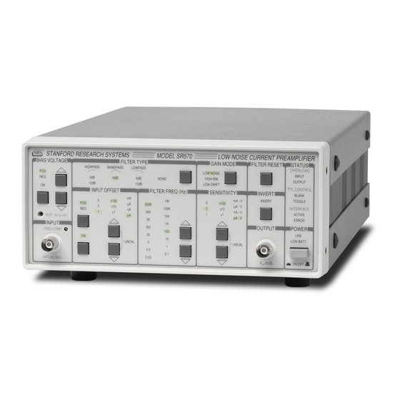
- Page 1 MODEL SR570 Low-Noise Current Preamplifier 1290-D Reamwood Avenue Sunnyvale, California 94089 Phone: (408) 744-9040 • Fax: (408) 744-9049 email: infor@thinkSRS.com • www.thinkSRS.com Copyright © 1997 by SRS, Inc. All Rights Reserved. Revision 1.6 (03/2005)
-
Page 3: Table Of Contents
SR570 Low-Noise Current Preamplifier Table of Contents Programming Remote Programming Condensed Information Introduction Command Syntax Safety and Use Accessories Furnished Detailed Command List Environmental Conditions Sensitivity Control Symbols Input Offset Current Control Specifications Bias Voltage Control Verifying Specifications Filter Control... - Page 4 SR570 Low-Noise Current Preamplifier 1/f Noise Total Noise External Noise Sources Capacitive Coupling Inductive Coupling Ground Loops Microphonics Thermocouple Effects Baluns B. Gain Allocation Front-end Amplifier Op Amp Allocation Dynamic Reserve C. Capacitance Effects Feedback Capacitance Input Capacitance Component Parts List Main Circuit PC Board Front &...
-
Page 5: Safety And Preparation For Use
The internal batteries are charged as long as AC VENTILATION power is connected. Always ensure adequate ventilation when The SR570 operates from a 100V, 120V, 220V, or operating the SR570. The unit will generate heat 240V nominal AC power source having a line while charging batteries. -
Page 6: Accessories Furnished
SR570 Low-Noise Current Preamplifier REPACKAGING FOR SHIPMENT connect the PMT output to the SR570 input before turning the PMT on. The original packing materials should be saved for reshipment of the SR570. If the original packing ACCESSORIES FURNISHED materials are not available, wrap the instrument in... -
Page 7: Specifications
Specifications... - Page 8 Specifications Input Input Virtual null or user set bias voltage (-5V to +5V). Input Impedance See Table 1 Input Offset ±1 pA to ±5 mA full scale adjustable dc offset current. Maximum Input ±5 mA. Noise See graphs on next page. Sensitivity 1 pA/V to 1 mA/V in a 1-2-5 sequence.
- Page 9 Specifications Low Noise Mode High Bandwidth Mode 1 nA/V 10 µA/V 1 nA/V 10 µA/V 100 nA/V 1 mA/V 100 nA/V 1 mA/V Frequency (Hz) Frequency (Hz) Amplifier Bandwidth for several sensitivity settings (typical). Low Noise Mode High Bandwidth Mode 1 mA/V 1 mA/V 10 µA/V...
- Page 10 Specifications Table 1 Temperature Coefficient Bandwidth (3 dB) 1 Noise/√Hz Low Drift (11 ° - 28 °C) DC Input Sensitivity (A/V) High BW Low Noise Low Noise High BW ±(%input + offset) /°C Impedance 1 Ω 10-3 1.0 MHz 1.0 MHz 150 pA 150 pA 0.01 % + 20 nA...
-
Page 11: Verifying Specifications
To verify the specifications given for the sensitive measurements: SR570 current amplifier, a few straightforward procedures should be 1. Make sure the source impedance is greater followed. First, the unit must be warmed up than the inverse of the sensitivity (e.g. -
Page 12: Abridged Command List
<CR><LF>. The SR570 RS232 interface is configured as listen only, 9600 baud DCE, 8 data bits, no parity, 2 stop bits, and is optically isolated to prevent any noise or grounding problems. -
Page 13: Operation And Controls
Overview the up/down arrow keys. The current will be applied when the "ON" led is lit. The SR570 is a low-noise current preamplifier, providing a voltage output proportional to the 5) When the bias voltage is off, the amplifier input input current. -
Page 14: Sr570 Block Diagram
Operation and Controls Figure 1: SR570 Block Diagram... -
Page 15: Front Panel Operation
Any changes made to the front panel settings of the amplifier power is derived from regulated line SR570 will be stored even when power is turned off, power, and the internal batteries are as long as the batteries are hooked up. To reset the automatically charged. -
Page 16: Bias Voltage
Operation and Controls the batteries from an SR570 with no AC power restore the unit to the previously calibrated current connected will reset the unit to the default state. setting, and turn off the UNCAL LED. The sign of The default settings are: the current is set with the button directly below the POS and NEG LEDs. -
Page 17: Gain Mode
See constants, the FILTER RESET pushbutton will Appendix B for further details of op amp speed the SR570's recovery from overload. The selection for the different gain modes. filters will be discharged by momentarily grounding the filter capacitors. -
Page 18: Status
The BLANK LED indicates that the optoisolated reserve is too low. Reducing the sensitivity, BLANK input (on the rear panel of the SR570) is reducing the input signal and/or switching to the active. The SR570 responds to a blanking input by HIGH BW setting should remedy this condition. -
Page 19: Rear Panel Operation
Figure 3: SR570 Rear Panel connected to the AC line ground conductor. REAR PANEL OPERATING SUMMARY The SR570 rear panel is pictured in Figure 3. Battery Charger Various interface and power connectors are provided, along with fuses and charger status Two 3 A “slo-blo”... -
Page 20: Blanking Input
TTL used in the SR570 differ in this respect from nickel- cadmium batteries, which behave in exactly the square wave, then a DC component will be produced that is proportional to the signal opposite manner. - Page 21 Avoiding deep discharge will provide the longest battery life – upwards of When not in use, the SR570 should be stored in a 1,000 charge / discharge cycles. cool, dry place with the batteries fully charged. This reduces the self-discharge of the batteries and •...
-
Page 22: Programming
Sensitivity control commands Introduction SENS n Sets the sensitivity of the amplifier The SR570 is equipped with a standard DB-25 according to the following table: RS-232 connector on the rear panel for remote control of all instrument functions. The scale... -
Page 23: Bias Voltage Control
IOSN n Sets the input offset current sign. 0 = HFRQ n Sets the value of the highpass filter 3dB neg, 1 = pos. point. n ranges from 0 (0.03Hz) to 11 (10 kHz). See table below. IOUC n Sets the input offset cal mode. 0 = filter frequency cal, 1 = uncal. -
Page 24: Programming Examples
Program Example 1 IBM PC, BASIC, via RS232 In this example, the IBM PC's COM2 serial port is used to communicate with the SR570. The program sets up the SR570 for a typical measurement. 10 ' Example program to set up for a measurement. This 20 ' program uses IBM Basic and communicates via the COM2:RS-232 port. -
Page 25: Microsoft C
IBM PC, Microsoft C, via RS232 In this example, the IBM PC's COM2 serial port is used to communicate with the SR570. The program asks the user to enter an SR570 command to send to the instrument. Before running the program, use the DOS 'MODE' command to set up the serial port parameters, e.g. -
Page 26: Circuit Description
CONFIGURABLE FILTERS AND LOW-NOISE Current to Voltage FRONT GAIN The two filter stages in the SR570 each consist of 16 The current signal to be amplified is connected R-C filters which can be configured as either high to BNC J104. Relays K103, K104, & K105 pass or low pass by a relay. -
Page 27: Overload Detection
RS-232 port. the charging circuits while not charging, and D707 and D708 are clamps to guard against battery The SR570 uses a 8 K x 8 CMOS polarity reversal. EPROM,(U504) containing system firmware and calibration bytes, along with a 2 K x 8... -
Page 28: Power Regulators
BATTERIES AND P.E.M. POWER REGULATORS The batteries used in the SR570 are of sealed lead- The +5 V and +10 V supplies are produced with acid construction. There are three 12 volt, 1.9 amp-... -
Page 29: Calibration & Repair
BATTERY REPLACEMENT across R105. After three to five years or about 1000 Turn on the SR570. Select a 1 mA input offset charge/discharge cycles, the sealed lead-acid current and 1 mA/V sensitivity from the front batteries degrade. When the battery operation time panel. - Page 30 The other two fuses are in-line with the batteries and are rated at 3 A. These fuses will blow if the rear panel ±12 VDC supplies are shorted or if excess current flows to or from the batteries.
-
Page 31: Amplifier Noise Sources
Kelvin (typically 300 K), R is the resistance in Ohms, and Df is the bandwidth of The input noise of the SR570 current amplifier the measurement in Hz. Using this formula, the varies depending upon the sensitivity setting. On... -
Page 32: 1/F Noise
1/f noise Capacitive coupling Every 10W resistor, no matter what An AC voltage from a nearby piece of apparatus can composition, has the same Johnson noise. couple to a detector via a stray capacitance. However, there is excess noise in addition to Although Cstray may be very small, the coupled Johnson noise which arises from fluctuations in noise may still be larger than a weak experimental... -
Page 33: Inductive Coupling
Inductive coupling Experiment Detector An AC current in a nearby piece of apparatus can couple to the experiment via a magnetic field. A changing current in a nearby circuit gives rise to a changing magnetic field which I(t) induces an emf (dØB/dt) in the loop connecting the detector to the experiment. -
Page 34: Thermocouple Effects
A few words about Baluns dC/dt will give rise to a current in the cable. This current affects the detector and the To reduce the effects of ground loops, the SR570 measured signal. has a balun (BALanced/UNbalanced common-mode choke) connected to the output stage. This may be... -
Page 35: Front-End Amplifier
The term “Dynamic Reserve” comes up frequently in discussions about amplifiers. It’s In the SR570, decreasing front-end gain to increase time to discuss this term in a little more detail. dynamic reserve can only be accomplished by Assume the amplifier input consists of a full decreasing the value of the input op amp’s feedback... - Page 36 The DR rises to a maximum which depends on the SR570 set to sensitivities of 20 µA/V, 50 µA/V, gain distribution in the amplifier circuit. The plot and 100 µA/V, with the high pass filter set to...
- Page 37 13! Even more important is that this gain In the SR570, we have implemented a variable increases with increasing values of input feedback capacitance across the amplifier which capacitance.
- Page 39 Parts List Main Circuit Board Parts List B 401 6-00137-601 15MH Inductor C 101 5-00100-517 2.2U Capacitor, Tantalum, 35V, 20%, Rad C 102 5-00100-517 2.2U Capacitor, Tantalum, 35V, 20%, Rad C 103 5-00225-548 .1U AXIAL Capacitor, Ceramic, 50V,+80/-20% Z5U AX C 104 5-00225-548 .1U AXIAL...
- Page 40 Parts List C 223 5-00031-520 220U Capacitor, Electrolytic, 16V, 20%, Rad C 224 5-00232-520 470U Capacitor, Electrolytic, 16V, 20%, Rad C 225 5-00232-520 470U Capacitor, Electrolytic, 16V, 20%, Rad C 226 5-00192-542 22U MIN Cap, Mini Electrolytic, 50V, 20% Radial C 227 5-00192-542 22U MIN...
- Page 41 Parts List C 410 5-00100-517 2.2U Capacitor, Tantalum, 35V, 20%, Rad C 411 5-00100-517 2.2U Capacitor, Tantalum, 35V, 20%, Rad C 412 5-00100-517 2.2U Capacitor, Tantalum, 35V, 20%, Rad C 413 5-00002-501 100P Capacitor, Ceramic Disc, 50V, 10%, SL C 414 5-00022-501 .001U Capacitor, Ceramic Disc, 50V, 10%, SL...
- Page 42 Parts List C 825 5-00100-517 2.2U Capacitor, Tantalum, 35V, 20%, Rad C 826 5-00100-517 2.2U Capacitor, Tantalum, 35V, 20%, Rad C 827 5-00023-529 Cap, Monolythic Ceramic, 50V, 20%, Z5U C 828 5-00023-529 Cap, Monolythic Ceramic, 50V, 20%, Z5U C 829 5-00023-529 Cap, Monolythic Ceramic, 50V, 20%, Z5U C 830...
- Page 43 Pot, Multi-Turn Trim, 3/8" Square Top Ad P 701 4-00011-441 Pot, Multi-Turn Trim, 3/8" Square Top Ad P 702 4-00011-441 Pot, Multi-Turn Trim, 3/8" Square Top Ad 7-00468-701 SR570 MAIN Printed Circuit Board Q 501 3-00021-325 2N3904 Transistor, TO-92 Package Q 701 3-00310-329 MTP25N05 Voltage Reg., TO-220 (TAB) Package...
- Page 44 Parts List R 118 4-00398-407 499K Resistor, Metal Film, 1/8W, 1%, 50PPM R 119 4-00030-401 Resistor, Carbon Film, 1/4W, 5% R 120 4-00030-401 Resistor, Carbon Film, 1/4W, 5% R 121 4-00776-407 Resistor, Metal Film, 1/8W, 1%, 50PPM R 122 4-00136-407 1.82K Resistor, Metal Film, 1/8W, 1%, 50PPM R 123...
- Page 45 Parts List R 217 4-00325-407 Resistor, Metal Film, 1/8W, 1%, 50PPM R 218 4-00030-401 Resistor, Carbon Film, 1/4W, 5% R 219 4-00030-401 Resistor, Carbon Film, 1/4W, 5% R 220 4-00296-407 Resistor, Metal Film, 1/8W, 1%, 50PPM R 221 4-00165-407 Resistor, Metal Film, 1/8W, 1%, 50PPM R 222 4-00165-407 Resistor, Metal Film, 1/8W, 1%, 50PPM...
- Page 46 Parts List R 402 4-00165-407 Resistor, Metal Film, 1/8W, 1%, 50PPM R 403 4-00165-407 Resistor, Metal Film, 1/8W, 1%, 50PPM R 404 4-00030-401 Resistor, Carbon Film, 1/4W, 5% R 405 4-00030-401 Resistor, Carbon Film, 1/4W, 5% R 406 4-00325-407 Resistor, Metal Film, 1/8W, 1%, 50PPM R 407 4-00190-407 42.2K...
- Page 47 Parts List R 704 4-00022-401 1.0M Resistor, Carbon Film, 1/4W, 5% R 705 4-00169-407 Resistor, Metal Film, 1/8W, 1%, 50PPM R 706 4-00042-401 Resistor, Carbon Film, 1/4W, 5% R 707 4-00042-401 Resistor, Carbon Film, 1/4W, 5% R 708 4-00376-407 2.87K Resistor, Metal Film, 1/8W, 1%, 50PPM R 709 4-00169-407...
- Page 48 Parts List R 817 4-00094-401 6.8K Resistor, Carbon Film, 1/4W, 5% R 818 4-00079-401 4.7K Resistor, Carbon Film, 1/4W, 5% R 819 4-00022-401 1.0M Resistor, Carbon Film, 1/4W, 5% SO504 1-00026-150 28 PIN 600 MIL Socket, THRU-HOLE SO708 1-00570-150 16 PIN Socket, THRU-HOLE SO709 1-00570-150...
- Page 49 Parts List U 505 3-00081-341 2KX8-100 STATIC RAM, I.C. U 506 3-00039-340 74HC14 Integrated Circuit (Thru-hole Pkg) U 507 3-00158-340 74HC154N Integrated Circuit (Thru-hole Pkg) U 508 3-00049-340 74HC74 Integrated Circuit (Thru-hole Pkg) U 509 3-00277-340 74HC11 Integrated Circuit (Thru-hole Pkg) U 510 3-00537-340 74HC373...
- Page 50 Parts List D 12 3-00012-306 GREEN LED, Rectangular D 13 3-00012-306 GREEN LED, Rectangular D 14 3-00012-306 GREEN LED, Rectangular D 15 3-00012-306 GREEN LED, Rectangular D 16 3-00012-306 GREEN LED, Rectangular D 17 3-00012-306 GREEN LED, Rectangular D 18 3-00012-306 GREEN LED, Rectangular...
- Page 51 470X5 Resistor Network SIP 1/4W 2% (Common) 4-00298-425 470X5 Resistor Network SIP 1/4W 2% (Common) 4-00802-452 2.0K Pot, Multi Turn Trim, Mini 7-00469-701 SR570 FP Printed Circuit Board 3-00022-325 2N3906 Transistor, TO-92 Package 3-00022-325 2N3906 Transistor, TO-92 Package 3-00021-325 2N3904...
- Page 52 Parts List SW10 2-00031-201 D6-01-05 Switch, Momentary Push Button SW11 2-00031-201 D6-01-05 Switch, Momentary Push Button SW12 2-00031-201 D6-01-05 Switch, Momentary Push Button SW13 2-00031-201 D6-01-05 Switch, Momentary Push Button SW14 2-00031-201 D6-01-05 Switch, Momentary Push Button SW15 2-00031-201 D6-01-05 Switch, Momentary Push Button 3-00303-340 74HC164...
- Page 53 Capacitor, Ceramic Disc, 50V, 20%, Z5U 6-00004-611 1A 3AG Fuse 6-00050-612 GB1219-36 Battery 6-00074-611 3A 3AG Fuse 7-00201-720 SR500-32 Fabricated Part 7-00460-709 SR570 Lexan Overlay 7-00462-709 SR570 Lexan Overlay 7-00463-720 SR570-4&5 Fabricated Part 7-00464-720 SR570-6 Fabricated Part 7-00795-720 BATTERY PAN Fabricated Part...
- Page 54 Screw, Panhead Phillips 0-00326-026 8-32X1/4PP Screw, Black, All Types 0-00471-021 4-40X1"PP Screw, Panhead Phillips 7-00122-720 DG535-36 Fabricated Part 7-00217-735 PS300-40 Injection Molded Plastic 7-00259-720 SR560-28 Fabricated Part 7-00260-720 SR560-27 Fabricated Part 7-00465-720 SR570-7 Fabricated Part 7-00466-720 SR570-8 Fabricated Part D-16...
Need help?
Do you have a question about the SR570 and is the answer not in the manual?
Questions and answers