Table of Contents
Advertisement
Quick Links
Advertisement
Table of Contents

Subscribe to Our Youtube Channel
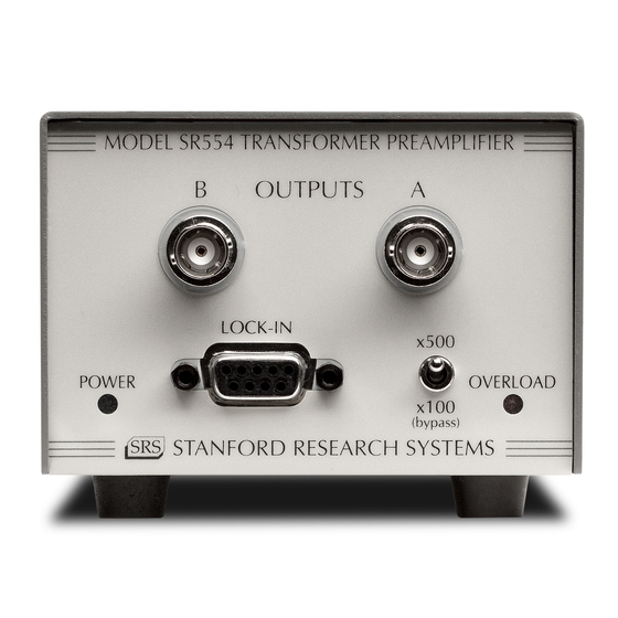
Summary of Contents for Stanford Research Systems SR554
- Page 1 Model SR554 Transformer Preamplifier 1290-D Reamwood Avenue Sunnyvale, California 94089 Phone: (408) 744-9040 • Fax: (408) 744-9049 email: info@thinkSRS.com • www.thinkSRS.com Copyright © 1999 by SRS, Inc. All Rights Reserved. Revision 1.2 (10/2001)
- Page 3 SR554 SPECIFICATIONS Inputs Single ended or differential 0.5 Ω Input Impedance Maximum Inputs Transformer and Buffer: 14.0 mV RMS (±20 mV peak) Transformer only: 350 mV RMS (±0.5 V peak) Common Mode Range: ± 100 VDC Rejection: 140 dB @ 100 Hz Isolation >...
-
Page 5: Operation
When used the SR554 can be used in the bypassed as a simple transformer, power mode. In the bypassed mode, the output connection is required. -
Page 6: Output Connection
(±0.5 V peak). Care should be taken when For single ended operation the (A) Output the unit is used in the bypassed mode, of the SR554 should be connected to the since a ±0.5 V peak input becomes ±50 V (A) Input of the lock-in amplifier. - Page 7 GAIN OF SR554 cables should be twisted together to prevent inductive pick-up. The actual gain of the SR554 is a function of the source impedance, frequency and For most experiments it is preferable to the set gain. In the bypass mode (x100), use the SR554 in the buffered mode.
-
Page 8: Noise Figure
Measurements made using the preamp in chassis (using a lug under one of the must be divided by the gain of the SR554. chassis screws) to the grounding lug of The actual gain can be obtained from the the SR554. -
Page 9: Common Mode Rejection Ratio
If a ground is not available LOCK-IN near the experiment, connect a wire to the The SR554 can be powered with an lock-in using a lug under one of the external power supply. Power is applied chassis screws. -
Page 11: Performance Tests
11 mV 2. 50 Ω Ω Ω Ω T erminator 5) Disconnect the lock-in reference from the SR554 input. Connect the 50 Ω 3. 50 Ω Ω Ω Ω , 20 dB Attenuator terminator to the SR554 (A) input. -
Page 13: Part List
L 101 6-00174-630 6611 TYPE 43 Ferrite Beads L 102 6-00174-630 6611 TYPE 43 Ferrite Beads 7-00613-701 SR554 PREAMP Printed Circuit Board R 101 4-00141-407 Resistor, Metal Film, 1/8W, 1%, 50PPM R 102 4-00188-407 4.99K Resistor, Metal Film, 1/8W, 1%, 50PPM... - Page 14 8-1/2" #22 BLK Wire #22 UL1007 0-00304-043 7/8X3/8X1/16 Washer, nylon 0-00386-003 SOLDR SLV RG174 Termination 0-00440-052 2-1/2" #22 RED Wire #22 UL1007 7-00604-720 SR554-1 Fabricated Part 7-00605-720 SR554-2 Fabricated Part 7-00606-720 SR554-3 Fabricated Part 7-00607-709 SR554 Lexan Overlay 9-00267-917 GENERIC...


Need help?
Do you have a question about the SR554 and is the answer not in the manual?
Questions and answers