
Related Manuals for Stanford Research Systems SR124


Summary of Contents for Stanford Research Systems SR124
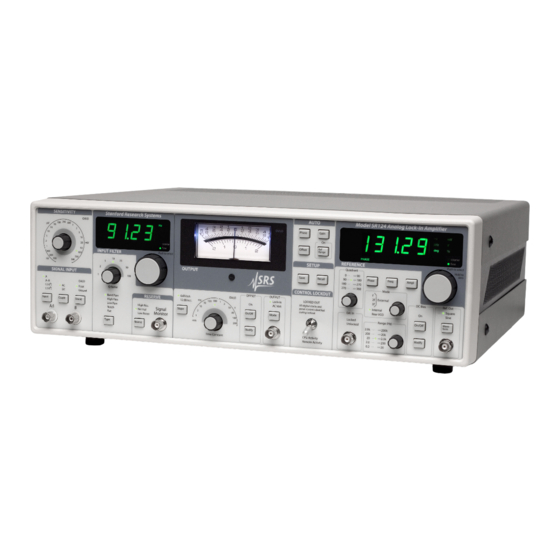
- Page 1 Operation and Service Manual Analog Lock-In Amplifier SR124 Stanford Research Systems Revision 1.03 July 12, 2018...
- Page 2 (1) year from the date of shipment. Service For warranty service or repair, this product must be returned to a Stanford Research Systems authorized service facility. Contact Stanford Research Systems or an authorized representative before returning this product for repair.
-
Page 3: Table Of Contents
2.1.2 What does the SR124 measure? ..2 – 2 Instrument overview ....2 – 3 2.2.1... - Page 4 5.4 Front Panel ......5 – 2 5.5 Main board ......5 – 2 SR124 Analog Lock-In Amplifier...
- Page 5 5.8 Communications ..... 5 – 5 5.9 Schematics ......5 – 5 SR124 Analog Lock-In Amplifier...
- Page 6 Contents SR124 Analog Lock-In Amplifier...
-
Page 7: General Information
AC line voltage The SR124 Analog Lock-In Amplifier operates from a 100 V, 120 V, 220 V, or 240 V nominal AC power source having a line frequency of 50 Hz or 60 Hz. Before connecting the power cord to a power source,... -
Page 8: Symbols
Symbols you may Find on SRS Products Symbol Description Alternating current Caution - risk of electric shock Frame or chassis terminal Caution - refer to accompanying documents Earth (ground) terminal Battery Fuse On (supply) Off (supply) SR124 Analog Lock-In Amplifier... -
Page 9: Notation
Literal text other than command names is set as OFF Remote command examples will all be set in monospaced font. In these examples, data sent by the host computer to the SR124 are set as straight teletype font, while responses received by the host computer from the SR124 are set as slanted teletype font. -
Page 10: Specifications
Up to 80 dB attenuation CMRR 90 dB below 10 kHz, DC coupled decreasing by 6 dB oct above 10 kHz Dynamic reserve (without band pass filter) Low noise 20 dB Normal 40 dB High reserve 60 dB SR124 Analog Lock-In Amplifier... - Page 11 1% for upper decade of each range 5% for lower decade of each range Amplitude stability 50 ppm C, typ. Output impedance DC bias commandable, to 10 amplitude, or 10 VDC max (amp. dependent; see section 3.4 for details) SR124 Analog Lock-In Amplifier...
- Page 12 Parameter Specification Temperature 0 C to 40 C, non-condensing Power 40 W, 100 120 220 240 VAC, 50 60 Hz Dimensions 17 W 15 D Weight 23 lbs Fuse Type 5MF, 5 20 mm, “fast blow” SR124 Analog Lock-In Amplifier...
-
Page 13: Getting Started
1 Getting Started This chapter provides step-by-step instruction to get started quickly with the SR124 Analog Lock-In Amplifier. Refer to chapter 2 for a more complete introduction to the SR124. In This Chapter 1.1 How to use this manual ....1 – 2 Basic instrument check-out . -
Page 14: How To Use This Manual
Those who want to begin with an overview to the functional layout of the instrument should turn to Chapter 2. Users who prefer to jump in and begin using the SR124 first should continue with this Chapter, where a series of step-by-step procedures are given to verify the basic performance of the instrument. -
Page 15: Signal And Input Filter
10. Press the INPUT FILTER inward once more, to illuminate the depth indicator. 11. Adjust the depth trim by turning INPUT FILTER to mim- imize the meter deflection (minimum is somewhat sensitive to depth ). SR124 Analog Lock-In Amplifier... -
Page 16: Phase Sensitive Detector
[Recall] again. 2. Change the reference frequency from 1.000 kHz to 100 Hz by turning the Range knob counterclockwise one click. Turn the large REFERENCE knob counterclockwise to set the fre- quency to 47 Hz. SR124 Analog Lock-In Amplifier... -
Page 17: Reserve
REFERENCE if necessary to display ”deFLt”, and then press [Recall] again. 2. Perform an auto-phase adjustment by pressing [Phase] in the AUTO block. After the pause, the phase should show a value near 0 deg. SR124 Analog Lock-In Amplifier... -
Page 18: Output O Set
1.7 Output offset 1. Restore default settings pressing [Recall]; turn REFERENCE if necessary to display ”deFLt”, and then press [Recall] again. SR124 Analog Lock-In Amplifier... -
Page 19: Reference Oscillator External Input
[Recall] again. 2. Set the function generator to produce a 1 Vrms, 2 kHz sine wave. Connect the function generator output to the SR124 “Ext. In” BNC, in the REFERENCE section. 3. Turn the Mode knob in the REFERENCE section one click clockwise, to the f External setting. -
Page 20: Reference Oscillator Output
270 output. Verify the Channel 2 signal on the scope lags Channel 1 by 270 (leading by 90 ). 6. Disconnect the Channel 2 BNC from the rear-panel of the SR124, and connect it to the front-panel Ref. Out BNC. - Page 21 REFERENCE counterclockwise until you reach the limit. Turn the knob slow counterclockwise to reach 10.0 mV. Notice that the SR124 will not allow the Amplitude to decrease below 10.0 mV with the DC Bias enabled and set to 2 V.
- Page 22 1 – 10 Getting Started SR124 Analog Lock-In Amplifier...
-
Page 23: Introduction
2.1.2 What does the SR124 measure? ..2 – 2 Instrument overview ....2 – 3 2.2.1... -
Page 24: Introduction To The Instrument
2.1.2 What does the SR124 measure? In lock-in mode, the SR124 multiplies the input signal by a square wave at the reference frequency, using a square-wave analog mixer. The resulting signal is then low-pass filtered to produce an output proportional to the frequency component of the user’s input signal at... -
Page 25: Instrument Overview
BNC, while a full scale signal 180 out of phase will generate 10 V. Lock-in amplifiers as a general rule display the input signal in volts RMS, and this is the basis for the SR124 calibration as well. For example, if the SR124 is configured for 2 mV sensitivity and a... - Page 26 2.2.1.3 External mode The SR124 oscillator can lock to an external reference signal applied to the Ext. In BNC connector. This input operates in two distinct modes, sine input and TTL input (indicated by the TTL indicator just above the connector).
- Page 27 2.2.1.4 Reference output The SR124 reference oscillator drives the front-panel Ref. Out BNC signal. This output can be configured as either sine wave or square wave. The amplitude of the reference output can be set from 10 V to 100 nVrms;...
-
Page 28: Signal Section
BNC cables should be used to connect the preamp output to the lock-in signal input. 2.2.2.2 Current preamplifier The current input on the SR124 uses the A input BNC. Two internal gain settings are available: 10 Volts Amp and 10 Volts Amp. - Page 29 The overall sensitivity of the SR124 in current mode is dependent on the Sensitivity setting. The current preamplifier itself converts the input current signal to a low-level voltage with the specified tran-...
- Page 30 For example, if the SR124 is operating at full scale sensitivity of 1 V, and an interfering signal of up to 1 mV can be rejected before overloading, the dynamic reserve is 60 dB.
-
Page 31: Input Filter
1 Q. See section 3.3 for the detailed filter transfer functions of the SR124 input filter. SR124 Analog Lock-In Amplifier... -
Page 32: Output
1 second time constant refers to a filter whose -3 dB point occurs at 0.16 Hz. In the SR124 the user can select one or two successive stages of output filter, so that the overall filter can roll o is either 6 dB or 12 dB per octave. -
Page 33: Navigating The Front Panel
2.3 Navigating the front panel The front panel of the SR124 is organized into distinct functional sections. Knowing this organization will help you to become familiar with its operation. A diagram of the entire front panel is in Figure 2.2, below. -
Page 34: Signal Input Section
Figure 2.3: The SR124 front panel signal input section. 2.3.1.1 Signal input User input signals are applied to the SR124 through the “A I”, or the “A I” and “B” BNC connectors. The input configuration is controlled SR124 Analog Lock-In Amplifier... - Page 35 2.3.1.2 Sensitivity The overall gain of the SR124 is controlled by setting the sensitivity. Full scale sensitivities from 100 nV to 500 mV, in 1–2–5 steps, can be selected by turning the SENSITIVITY knob. (SENS, 4 – 13 ) Overloads in the AC signal path, after the preamplifier but before the...
- Page 36 2 – 14 Introduction same amount of noise as the real filter in question. For the SR124 input filter operating in band pass mode, with the filter frequency set to f and Q-factor set to Q, the ENBW is given by...
-
Page 37: Output Section
600 Ω Figure 2.4: The SR124 front panel output section. The panel meter shows the output signal from the SR124. This is the same signal as appears at the output BNC. The meter shows 100% deflection when the BNC output is 10 V, and 100% deflection when the BNC output is 10 V. -
Page 38: Setup Section
1000% and 1000% of full scale. (OFST, 4 – 15 ) 2.3.2.3 Output The overall functional mode of the SR124 is controlled by the [Mode] button within the OUTPUT block. Pressing [Mode] toggles between Lock-In and AC Volt modes. (OMOD, 4 – 14 ) The output signal from the SR124 is available on the BNC output connector within the OUTPUT block. - Page 39 [Recall] again to restore those settings. Pressing any other key will abandon the recall request. (RSET, 4 – 15 ) When the SR124 is in REM mode (remote control), pressing the [Re- call] button asserts the “Local” function and returns the instrument to local mode.
-
Page 40: Reference Section
2 – 18 Introduction 2.3.3.3 Control inhibit The SR124 user interface controls can be inhibited by setting the control inhibit switch to the upper position. Note that this is a locking toggle switch, and must be gently pulled outwards while switching upwards or downwards. - Page 41 (QUAD, 4 – 9 ) 2.3.4.2 Ext. In The Ext. In BNC input is used for locking the SR124 to an external reference; this input is unused when in Internal or Rear VCO mode. The Ext. In circuit can be configured for either sine inputs or TTL inputs;...
- Page 42 The Ref. Out BNC connector provides the refence output signal. The RMS amplitude of the signal is adjusted with the AMPL parameter. Pressing [Shape] toggles between sine output and square output. (FORM, 4 – 11 ) SR124 Analog Lock-In Amplifier...
-
Page 43: Performance Details
3 Performance Details This chapter provides a detailed discussion of the operating charac- teristics and architecture of the SR124. In This Chapter 3.1 Sensitivity and gain ....3 – 2 3.1.1... -
Page 44: Sensitivity And Gain
3 – 2 Performance Details 3.1 Sensitivity and gain While not necessary to operate the SR124, many users will still find detailed information about gain allocation helpful for optimizing measurements. 3.1.1 AC Gain Table 3.1: AC gain allocation Sensitivity Pre-... -
Page 45: Scale Normalization
(10 V) (200 V) 50,000. 3.1.2 Scale normalization The SR124 is calibrated for RMS units, but the square wave demod- ulator actually measures an absolute value average. As a result, there can be confusion about the precise values of gain used in the instrument. -
Page 46: Dc Gain
RMS value of the (square wave) input. 3.1.3 DC gain The DC gain is programmed by the SR124 to make up the di erence between the total AC gain and the required Overall Gain from Equa- tion (3.2). - Page 47 filter (all signals, when in Flat filter type), Table 3.3 gives the maximum sinewave inputs that can be applied to the signal input without overloading any part of the AC signal path including the PSD (mixer). SR124 Analog Lock-In Amplifier...
-
Page 48: Input Filter Details
The input filter is constructed as a state-variable filter with user- settable cuto frequency f and Q-factor. In the SR124, the peak gain of the input filter is calibrated to be unity. The nominal transfer functions are shown in the following figures. - Page 49 3.3 Input filter details 3 – 7 Band Pass Q = 1 Normalized frequency (f/f Figure 3.1: The SR124 band pass input filter gain High Pass Q = 1 Normalized frequency (f/f Figure 3.2: The SR124 high pass input filter gain...
- Page 50 3 – 8 Performance Details Low Pass Q = 1 Normalized frequency (f / f Figure 3.3: The SR124 low pass input filter gain Notch Filter Q = 1 -0.3 -0.2 -0.1 Normalized frequency (f/f Figure 3.4: The SR124 notch input filter gain...
-
Page 51: Attenuators And Dc Bias Constraints
This section discusses the constraints and required time for the functions. 3.5.1 Auto-phase The automatic phase cycle will adjust the phase setting of the SR124 to maximize the detected signal in Lock-in mode. Three steps occur in an auto-phase cycle: 1. -
Page 52: Auto-Gain
(increasing the gain), one step at a time, until an overload is detected. At each setting, the SR124 pauses for 5 output Time Constants, or 500 ms (whichever is longer), for settling. - Page 53 The final step in the process is to arm a comparator that waits for the next positive zero-crossing of the external frequency reference. When that comparator fires, the VCO oscillator is un-haulted, and the oscillation begins (approximately) in-phase with the external ref- erence. SR124 Analog Lock-In Amplifier...
- Page 54 3 – 12 Performance Details SR124 Analog Lock-In Amplifier...
-
Page 55: Remote Operation
4 Remote Operation This chapter describes operating the SR124 over the remote inter- faces. In This Chapter 4.1 Index of commands ....4 – 2 Alphabetic list of commands . -
Page 56: Index Of Commands
4 – 13 Input sensitivity RMOD(?) z 4 – 13 Reserve mode 4 – 14 Output filter time constant OFLT(?) z OFSL(?) z 4 – 14 Output filter slope Output OMOD(?) z 4 – 14 Output mode SR124 Analog Lock-In Amplifier... - Page 57 4 – 21 Standard event status *ESE(?) [i,] j 4 – 21 Standard event status enable *CLS 4 – 21 Clear status LEXE? 4 – 21 Last execution error LCME? 4 – 22 Last command error SR124 Analog Lock-In Amplifier...
-
Page 58: Alphabetic List Of Commands
IGND(?) z 4 – 12 Input shield grounding ISRC(?) z 4 – 11 Input source 4 – 15 Key clicks KCLK(?) z LCME? 4 – 22 Last command error LEXE? 4 – 21 Last execution error SR124 Analog Lock-In Amplifier... - Page 59 4 – 13 Input sensitivity SLVL(?) g 4 – 10 Reference output amplitude SSET(?) z 4 – 15 Save user settings TOKN(?) z 4 – 18 Token Mode TYPF(?) z 4 – 12 Input filter type SR124 Analog Lock-In Amplifier...
-
Page 60: Introduction
4 – 6 Remote Operation 4.3 Introduction Remote operation of the SR124 is through a simple command lan- guage documented in this chapter. Both set and query forms of most commands are supported, allowing the user complete control of the lock-in from a remote computer through RS-232, or through the optical fiber and the SX199 interface to GPIB, RS-232, or ethernet... -
Page 61: Commands
FMOD INTERNAL —or— FMOD 1 For queries that return token values, the return format (keyword or integer) is specified with the TOKN command. SR124 Analog Lock-In Amplifier... -
Page 62: Notation
In these examples, all data sent by the host computer to the SR124 are set as straight teletype font, while responses received by the host computer from the SR124 are set as slanted teletype font. The usage examples vary with respect to set query, optional parame- ters, and token formats. -
Page 63: Reference And Phase Commands
Queries in either external or rear-VCO modes return the most re- cently measured value of the oscillator frequency. Note that the FREQ? query itself does not initiate a new measurement of the oscil- lator frequency. That action is performed with the AREF command. Example: FREQ? 137.036000000 SR124 Analog Lock-In Amplifier... - Page 64 0.2 – 21 FRNG P2 0 2 – 210 FRNG 2 1 20 – 2.1 k FRNG 20 2 200 – 21 k FRNG 200 3 FRNG 2K 4 2 k – 210 k Example: FRNG 3. SR124 Analog Lock-In Amplifier...
-
Page 65: Input Commands
SENS command. For example, if ISRC CUR1E8 and SENS S50MV, then the overall sen- sitivity corresponding to a full-scale (10 V) output is 50 mV 500 pA Example: ISRC? SR124 Analog Lock-In Amplifier... -
Page 66: Filter Commands
IFTR(?) g Input filter frequency trim Set (query) the input filter frequency trim value to g . The default value is IFTR 0. The parameter g can range from 999 999, in dimensionless units. Example: IFTR -128 SR124 Analog Lock-In Amplifier... -
Page 67: Gain And Time Constant Commands
See ISRC command discription for a discussion of sensitivity when configured for current inputs. Example: SENS? S100UV RMOD(?) z Reserve mode Set (query) the input sensitivity setting to z (HIGH 0, NORMAL 1, LOWNOISE 2) . Example: RMOD 1 SR124 Analog Lock-In Amplifier... -
Page 68: Output Commands
Set (query) the output mode to z (LOCKIN 0, ACVOLT 1) . Example: OMOD? LOCKIN OFSE(?) z Output o set enable Set (query) the output o set mode to z (OFF 0, ON 1) . Example: OFSE 1 SR124 Analog Lock-In Amplifier... -
Page 69: Setup Commands
USER1 1, . . . , USER8 8, DEFAULT 9) . The set version of RSET retreives user settings from non-volatile block z and reconfigures the SR124 to those settings. The query form simply returns the name number of the most-recently retreived memory block. -
Page 70: Auto Commands
4 – 16 Remote Operation 4.4.10 Auto commands The following commands all cause the SR124 to perform a series of intermal measurements and adjustments. See section 3.5 for a discussion of how much time these functions may require. AGAN(?) [z] Auto gain Set (query) the auto gain function to z (OFF 0, ON 1) . -
Page 71: Data Transfer Commands
The relationship betwen OUTP? and ORTI? is ORTI? (OUTP? 10 V) where V is the full-scale voltage sensitivity, in volts. For example, if SENS 8 (S50UV), V V. Then if OUTP? 3.14, then ORTI? returns 0.000015700 (15.7 V input). SR124 Analog Lock-In Amplifier... -
Page 72: Interface Commands
Token response mode controls the formatting of response messages generated by the SR124 to remote queries of token-type values. When TOKN OFF, the SR124 responds with the numeric version of the token quantity. When TOKN ON, the text version is returned. - Page 73 When in LOCL REMOTE, the [Recall Local] button acts as the “local” function, bringing the SR124 back to the LOCL LOCAL state with full front-panel control. Note, however, that in LOCL LOCKOUT, even the...
-
Page 74: Status Commands
Reads the current value of the reference oscillator lock status. Returns a token, with values z (UNLOCKED 0, LOCKED 1, or NOTPLL 2). If the SR124 reference oscillator is operating in one of the external reference modes (FMOD EXT1F, FMOD EXT2F, or FMOD EXT3F), then the query LOCK? will return either UNLOCKED 0 or LOCKED 1 based on the current status. - Page 75 Query the last execution error code. A query of LEXE? always clears the error code, so a subsequent LEXE? will return 0. Valid codes are: Value Definition No execution error since last LEXE? Illegal value Wrong token Invalid bit Queue full Not compatible SR124 Analog Lock-In Amplifier...
- Page 76 Extra parameter(s) Null parameter(s) Parameter bu er overflow Bad floating-point Bad integer Bad integer token Bad token value Bad hex block Unknown token Example: *IDN LCME? The error (4, “Illegal set”) is due to the missing “?”. SR124 Analog Lock-In Amplifier...
-
Page 77: Status Model
At power-on, all status registers are cleared. 4.5.1 Status byte (SB) The Status Byte is the top-level summary of the SR124 status model. When enabled by the Service Request Enable register, a bit set in the Status Byte causes the MSS (Master Summary Status) bit to be set. -
Page 78: Service Request Enable (Sre)
(0) undef (0) OPC : Operation Complete. Set by the *OPC command. QYE : Query Error. Indicates data in the output queue has been lost. DDE : Device-Dependent Error. Indicates an internal command queue overflow. SR124 Analog Lock-In Amplifier... - Page 79 The ESE acts as a bitwise AND with the ESR register to produce the single-bit ESB message in the Status Byte Register (SB). The register can be set and queried with the *ESE(?) command. At power-on, this register is cleared. SR124 Analog Lock-In Amplifier...
- Page 80 4 – 26 Remote Operation SR124 Analog Lock-In Amplifier...
-
Page 81: Circuits
5 Circuits This chapter presents a brief description of the SR124 circuit design. A complete parts list and circuit schematics are included. In This Chapter 5.1 Overview of circuits ....5 – 2 Power Supply . -
Page 82: Overview Of Circuits
The following sections correspond to schematic pages at the end of the manual. 5.2 Power Supply The SR124 power supply board uses low-voltage AC power from the shielded transformer to power the instrument. Separate power nets are created for the oscillator, the main signal board, and the CPU Front-panel boards. - Page 83 When fully seated, the JFET should look like Figure 5.1. 6. After replacing the JFET, the o set voltage must be trimmed to near zero. Power must be applied to the SR124 with the top SR124 Analog Lock-In Amplifier...
-
Page 84: Oscillator
9. Return the top cover and reinstall all the screws. 5.6 Oscillator The Oscillator board contains the quadrature sinewave voltage- controlled oscillator. This board is mounted vertically, at the right- hand side of the SR124 chassis. SR124 Analog Lock-In Amplifier... -
Page 85: Rear Outputs
5.8 Communications The small Communications board, located near the power-entry module, contains the fiber optic transmit and receive components. A simple RS-232 driver circuit is also on this board. 5.9 Schematics Circuit schematic diagrams follow this page. SR124 Analog Lock-In Amplifier...
Need help?
Do you have a question about the SR124 and is the answer not in the manual?
Questions and answers