
Related Manuals for Stanford Research Systems SR446


Summary of Contents for Stanford Research Systems SR446
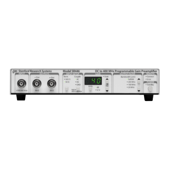
- Page 1 Operation and Service Manual 400 MHz Programmable Gain Preamplifier SR446 Stanford Research Systems Revision 1.01 November 18, 2022 •...
- Page 2 (1) year from the date of shipment. Service For warranty service or repair, this product must be returned to a Stanford Research Systems authorized service facility. Contact Stanford Research Systems or an authorized representative before returning this product for repair.
-
Page 3: Table Of Contents
Service ......2 Symbols on the SR446 ......3 Notation . - Page 4 B.3 Digital board ......29 B.4 Front panel board ..... . . 30 Schematic Diagrams SR446 400 MHz Programmable Gain Preamplifier...
-
Page 5: General Information
Service ......Symbols on the SR446 ..... . -
Page 6: Safety And Preparation For Use
Always use an outlet which has a properly connected protective ground. Service The SR446 400 MHz Programmable Gain Preamplifier does not have any user serviceable parts inside. Refer service to a qualified technician. Do not install substitute parts or perform any unauthorized modifications to this instrument. -
Page 7: Symbols On The Sr446
Toggle instrument power. Chassis Ground Notation Typesetting conventions used in this manual, with examples of each. Use case Example Front‑panel buttons [Term] Front‑panel indicators Remote command names *IDN? *IDN? Literal text (sent) Stanford_Research_Systems,SR446,00000001,3.11.2 Literal text (received) SR446 400 MHz Programmable Gain Preamplifier... -
Page 8: Specifications
+ 5 ° C to + 40 ° C, non‑condensing Mains voltage (85 to 264) Vac, (47 to 63) Hz Power 15 W (max), 5 W (typ) Weight 2.3 lb Dimensions 8.4 × 1.8 × 9.1, inches SR446 400 MHz Programmable Gain Preamplifier... -
Page 9: Frequency Response
Figure 1: Typical AC gain versus frequency. Measured with AC coupling, 50 Ω input impedance, and full bandwidth. Input signal generated with 50 Ω source impedance, amplitude adjusted for 130 mVpp sinusoidal output signal. SR446 400 MHz Programmable Gain Preamplifier... - Page 10 General Information SR446 400 MHz Programmable Gain Preamplifier...
-
Page 11: Operation
1.1 Introduction ......1.2 Using the SR446 ..... . . -
Page 12: Introduction
STAT? query is executed. The power standby indicator shows that the AC main power is connected and the SR446 is ready to be turned on. SR446 400 MHz Programmable Gain Preamplifier... -
Page 13: Using The Sr446
× -2 OL Protect Figure 1.3: SR446 block diagram. 1.2.1 Input Operation of the SR446 is described by the simplified block diagram (Figure 1.3). Input coupling is either , or , and is selected by pressing the [Couple] button. AC coupling is through a 100 nF capacitor, giving a 16 kHz −... -
Page 14: Gain
GAIN 1.2.3 Output filter The full bandwidth ( − 3 dB) of the SR446 is 400 MHz. In many situations, users may wish to reduce the output bandwidth. This can be helpful to block unwanted high‑frequency components of an amplified input signal, as well as to reduce the overall output noise for low‑bandwidth... -
Page 15: Special Operations
1.3 Special operations 1.3 Special operations 1.3.1 Offset calibration The SR446 has an automatic offset calibration feature that will trim the input offset voltage to within ± 1 mV of zero after operation. To trim the DC offset: 1. Ensure the unit has been on for at least 30 minutes to warm up. - Page 16 1 Operation SR446 400 MHz Programmable Gain Preamplifier...
-
Page 17: Remote Operation
2 Remote Operation This chapter describes operation of the SR446 400 MHz Programmable Gain Preamplifier via the remote interface. 2.1 List of Commands by Subject .... -
Page 18: List Of Commands By Subject
STAT? ... . Status Flags ........20 SR446 400 MHz Programmable Gain Preamplifier... -
Page 19: Introduction
STAT? query. 2.2.2 Buffers The SR446 stores incoming bytes from the remote interfaces in separate 500‑byte input buffers. Characters accumulate in the input buffer until a command terminator (the ⟨ CR ⟩ byte) is received, at which point the message is parsed and queued for execution. -
Page 20: Commands
Required parameter for set commands; illegal for queries 2.3.3 Examples Each command is provided with a simple example illustrating its usage. In these examples all data sent by the host computer to the SR446 are upright teletype set in font, while responses received by the host... -
Page 21: Interface Commands
*IDN? Identify Query the SR446 identification string. »*IDN? Example: Stanford_Research_Systems,SR446,00000001,3.11.2 *RST Reset Reset the SR446 to its default configuration. This is equivalent to the following command sequence: »ICPL 0 »INPZ 1 »UNIT 0 »GAIN 0 »BNDW 0 »*RST Example:... -
Page 22: Input Commands
GAIN(?) {i} Gain Sets (or queries) the amplifier gain. ( + 2 dB), ( + 4 dB), …, ( + 40 dB). (0 dB), »GAIN 12 Example: Sets the gain to + 24 dB SR446 400 MHz Programmable Gain Preamplifier... -
Page 23: Filter Command
(started from front panel), (calibration in progress), (calibration failed), or (calibration completed). Note that while OCAL is in progress, the SR446 will only respond to remote OCAL? queries–all other commands and queries will be ignored. »OCAL? Example: indicates calibration in progress FRST Factory Reset Initiates a factory reset. -
Page 24: Status Commands
+ Out output overload 65536 − Out output overload 131072 Bits remain latched to 1 until read by STAT? »ABCD Example: »STAT? indicates unknown command (”ABCD”) »STAT? bits cleared after previous STAT? query SR446 400 MHz Programmable Gain Preamplifier... -
Page 25: Performance Verification
40 dB (or 100 V/V). 3. Ensure the output filter is set to by pressing the OUTPUT full BW FILTER button. 4. Connect a BNC coax cable to the + Out connector on the SR446 front panel. SR446 400 MHz Programmable Gain Preamplifier... -
Page 26: Ac Gain
3.3 AC gain Gain accuracy is measured at 1 MHz, for each output, and at three gain setting of the SR446. For specified accuracy, coupling should be DC and input impedance 50 Ω . To configure the SR865A to verify the amplifier AC gain accuracy: 1. - Page 27 The following steps are repeated to measure the gain at 0 dB, 20 dB, and 40 dB: 1. Set the SR446 gain to the desired gain (0 dB, 20 dB, or 40 dB). 2. Pres the [Auto Scale] button on the SR865A, and wait at least 1 second.
- Page 28 3 Performance Verification SR446 400 MHz Programmable Gain Preamplifier...
-
Page 29: A Gain Calibration
+ 20 dB, and at 1 MHz. To configure the SR865A to calibrate the amplifier AC gain: 1. Both the SR865A and the SR446 should be powered on and warmed up, ideally for at least 2 hours. 2. Connect a 50 Ω terminator to the BNC tee, and connect the tee to the ”A”... - Page 30 10.00 mV as possible (must be between 9.90 mV and 10.10 mV). Make a note of the final value displayed as R. Figure A.1: Location of R412 and R512, near the front of the SR446 circuit board. SR446 400 MHz Programmable Gain Preamplifier...
- Page 31 BW 1. Set the SR446 gain to 20 dB. 2. Connect a BNC cable to the − Out connector on the SR446 and connect the other end to the BNC Tee on the SR865A. 3. Press the [Auto Scale] button on the SR865A, and wait at least 1 second.
- Page 32 Appendix A Gain Calibration SR446 400 MHz Programmable Gain Preamplifier...
-
Page 33: B Circuit Description
SR446. B.3 Digital board All configuration settings of the SR446 are performed by U10, an NXP Kinetis K10 microcontroller. The microcontroller uses an SPI serial port to configure the analog board for gain, filter selection, and relay configuration. -
Page 34: Front Panel Board
U9, U6, U4, U7, and U8. Button inputs are latched by parallel‑ loading shift register U11. The power/standby button is debounced by Schmitt trigger U10 and latched by flip‑flop U5, all of which are powered by the VAO +3.3V ”always on” power supply. SR446 400 MHz Programmable Gain Preamplifier... -
Page 35: Schematic Diagrams
Schematic Diagrams SR446 400 MHz Programmable Gain Preamplifier...
Need help?
Do you have a question about the SR446 and is the answer not in the manual?
Questions and answers