
Related Manuals for Stanford Research Systems SIM918


Summary of Contents for Stanford Research Systems SIM918
- Page 1 Operation and Service Manual Precision Current Preamplifier SIM918 Stanford Research Systems Revision 1.8 December 13, 2006...
- Page 2 (1) year from the date of shipment. Service For warranty service or repair, this product must be returned to a Stanford Research Systems authorized service facility. Contact Stanford Research Systems or an authorized representative before returning this product for repair.
-
Page 3: Table Of Contents
Contents General Information Safety and Preparation for Use ....Symbols ......Notation . - Page 4 Contents SIM918 Precision Current Preamplifier...
-
Page 5: General Information
No dangerous voltages are generated by the module. However, the outer shield of the front-panel Input coaxial (BNC) connector in the SIM918 can be switched to the rear-panel Program input. If a dangerous voltage is applied to the Program terminal, it may be present on the outer shell of the Input connector, and may cause injury or death. - Page 6 PMT can charge to several hundred volts in a relatively short time. If this cable is connected to the curent input of the SIM918, the stored charge may damage the front-end JFET. To avoid this problem, provide a leakage path of about 100 k to ground inside the base of the PMT to prevent charge accumulation.
- Page 7 General Information SIM918 Precision Current Preamplifier...
-
Page 8: Symbols
Symbols you may Find on SRS Products Symbol Description Alternating current Caution - risk of electric shock Frame or chassis terminal Caution - refer to accompanying documents Earth (ground) terminal Battery Fuse On (supply) Off (supply) SIM918 Precision Current Preamplifier... -
Page 9: Notation
Special ASCII characters are set as CR . Remote command examples will all be set in monospaced font. In these examples, data sent by the host computer to the SIM918 are set as straight teletype font, while responses received by the host computer from the SIM918 are set as slanted teletype font. -
Page 10: Specifications
Terminals Isolated BNC [6] BNC shield Ground, float Program input Voltage Resistance Terminals Grounded BNC [8], rear Reference clock sync Selection Input, output Interface Rear BNC [8], TTL [9] Input frequency [10] 0.90 1.10 Output frequency SIM918 Precision Current Preamplifier... - Page 11 [11] Non-condensing. General characteristics Interface Serial (RS–232) through SIM interface Connectors BNC (3 front [4], 2 rear [6]); DB–15 (male) SIM interface Weight 1.7 lbs Dimensions 1 5 W 3 6 H 7 0 D SIM918 Precision Current Preamplifier...
- Page 12 General Information SIM918 Precision Current Preamplifier...
-
Page 13: Getting Started
1 Getting Started This chapter gives you the necessary information to get started quickly with your SIM918 Precision Current Preamplifier. In This Chapter 1.1 Introduction to the Instrument ... . . 1 – 2 1.1.1... -
Page 14: Introduction To The Instrument
10 V A, remotely and from the front panel. Along with voltage accuracy, the SIM918 o ers a low input bias current and a current noise that is close to the lower limit imposed by the Johnson noise of the transimpedance. -
Page 15: Cabling And Grounding
flows through the center conductor to the SIM918. The shield of the Bias BNC can be inde- pendently grounded or floated. The input and bias selections, and those of their shields, can be made via the push of a front-panel button or remotely. -
Page 16: Block Diagram
R (1 1) bias bias A block diagram of the preamplifier is shown below in Figure 1.1. Main INPUT − BIAS offset OUTPUT − Difference − Zeroing (±1) Figure 1.1: The SIM918 block diagram. SIM918 Precision Current Preamplifier... -
Page 17: Front-Panel Operation
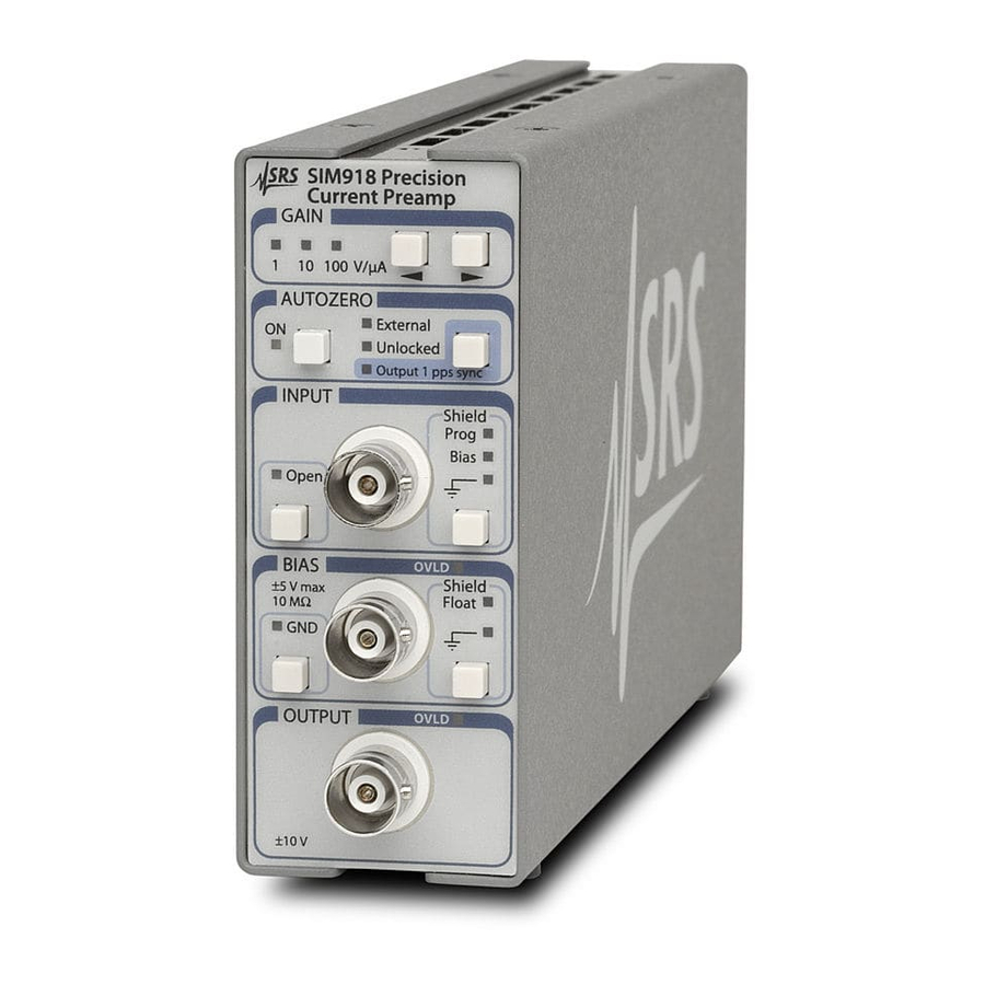
1.2 Front-Panel Operation 1 – 5 1.1.7 Front and rear panels Figure 1.2: The SIM918 front and rear panels. 1.2 Front-Panel Operation 1.2.1 Gain The gain R of the preamplifier, in volts per microampere, is indicated on the front panel of the instrument via a green annunciator LED. - Page 18 At the end of the pause, the LED indicator will turn o and all switching inside the SIM918 will cease. The sam- pled control output (trim) will remain applied to the transimpedance- stage amplifier, zeroing it to the best of precision available at the time...
-
Page 19: Input
The [INPUT Open] button opens and closes a relay in the path of the input current. A green LED indicates a disconnected input terminal. The input capacitance of the SIM918 is at its lowest with input open, and is specified in the table on Page viii. -
Page 20: Connections
50 ms; after this time it turns o if the overload condition has ceased. 1.3 Connections There are five BNC connectors in the SIM918, three on the front panel and two at the rear. Panel Terminal... -
Page 21: Power-On
. To reset the module into this configuration, turn the SIM900 Main- frame power on while holding a front-panel button of the SIM918 for at least 2.0 seconds. The same configuration can also be reached from the remote interface by issuing the *RST command. -
Page 22: Sim Interface
SIM918 is mated to a SIM900 Mainframe via this connection, either through one of the internal mainframe slots or the remote cable in- terface. It is also possible to operate the SIM918 directly, without using the SIM900 Mainframe. This section provides details on the interface. 1.6.1 SIM interface connector The DB–15 SIM interface connector carries all the power and commu-... - Page 23 RS–232 serial port of a personal computer. Connect RXD from the SIM918 directly to RxD on the PC, TXD directly to TxD. In other words, a null-modem-style cable is not needed. To interface directly to the DB–9 male (DTE) RS–232 port typically found on contemporary personal computers, a cable must be made with a female DB–15 socket to mate with the SIM918, and a female...
- Page 24 1.6.2.2 Serial settings The initial serial port settings at power-on are: baud rate 9600, 8 bits, no parity, 1 stop bit, and no flow control. The baud rate of the SIM918 cannot be changed. Flow control is not implemented in the SIM918.
-
Page 25: Description Of Operation
2 Description of Operation This chapter provides a number of additional details of the operation of the SIM918. In This Chapter 2.1 About Transimpedance Amplifiers ..2 – 2 2.1.1 Input capacitance and stability ..2 – 2 2.1.2... -
Page 26: About Transimpedance Amplifiers
Hence the term transimpedance. The main amplifier of the SIM918 Precision Current Preamplifier is a transimpedance amplifier based on a composite, JFET-input design. 2.1.1 Input capacitance and stability The input impedance of JFET devices is extremely large. -
Page 27: Choosing The Right Gain
( 10 MHz in the SIM918). Substituting into Equation (2.1), observe If the feedback element is purely resistive, the term due to Z haves exactly as if a large inductor were connected between the in- put and the bias terminals. -
Page 28: Bias And Ground
2.2 Bias and Ground 2.2.1 Grounds The output of the SIM918 is referenced to ground. To maintain the DC accuracy of the instrument, there are two separate ground references. Power Ground (Pin 8 of the SIM interface connector) provides a current return path for digital control signals, power- intensive analog amplifiers, and the power supplies. -
Page 29: Output
2.3 Output 2 – 5 To reduce output noise of the SIM918, the Bias input is limited to a bandwidth specified in the table on Page viii. Beyond this frequency, the transimpedance stage cannot follow variations in the bias voltage, but the output di erence amplifier (discussed in the next section) -
Page 30: Phase-Locked Loop
24 hours preceding a measurement. A valid au- tocalibration must take place at (23 5) C with the module warmed up for at least 2 hours at (23 5) C. If the module is being used inside SIM918 Precision Current Preamplifier... -
Page 31: Clock Stopping
LDDE? 2. Autocalibration does not a ect gain accuracy. 2.7 Clock Stopping The microprocessor clock of the SIM918 stops if the module is idle, “freezing” the digital circuitry. The following actions “wake up” the clock: 1. A power-on. -
Page 32: Quiescent Operation
Note that the operation of the PLL oscillator is completely indepen- dent of the microprocessor clock. 2.8 Quiescent Operation Follow these steps to operate the SIM918 Precision Current Preampli- fier in sensitive measurements that can tolerate absolutely no module clock transitions: 1. -
Page 33: Remote Operation
3 Remote Operation This chapter describes operating the SIM918 over the serial interface. In This Chapter 3.1 Index of Common Commands ... . . 3 – 2 Alphabetic List of Commands ... . . 3 – 4 Introduction . -
Page 34: Index Of Common Commands
3 – 16 Standard Event Status Enable CESR? [i] 3 – 17 Communication Error Status CESE(?) [i,] j 3 – 17 Communication Error Status Enable OLSR? [i] 3 – 17 Overload Status OLSE(?) [i,] j 3 – 17 Overload Status Enable SIM918 Precision Current Preamplifier... - Page 35 3 – 21 Execution Error 3 – 21 Command Error LCME? LDDE? 3 – 22 Device Error TOKN(?) z 3 – 22 Token Mode TERM(?) z 3 – 22 Response Termination Serial Communications PARI(?) z 3 – 23 Parity SIM918 Precision Current Preamplifier...
-
Page 36: Alphabetic List Of Commands
3 – 13 Reference Clock Frequency GAIN(?) m 3 – 12 Gain HELP(?) 3 – 10 Instrument Help INPT(?) z 3 – 12 Input LBTN? 3 – 18 Last Button LCME? 3 – 21 Command Error SIM918 Precision Current Preamplifier... - Page 37 READ? m 3 – 15 Read Microvoltmeter SHLD(?) y , z 3 – 13 Shield SYNC(?) z 3 – 13 Reference Clock Direction TERM(?) z 3 – 22 Response Termination TOKN(?) z 3 – 22 Token Mode SIM918 Precision Current Preamplifier...
-
Page 38: Introduction
3.3.2 Buffers The SIM918 stores incoming bytes from the host interface in a 64- byte input bu er. Characters accumulate in the input bu er until a command terminator (either CR or LF ) is received, at which point the message is parsed and executed. -
Page 39: Commands
CESR and ESR status registers. 3.3.3 Device Clear The SIM918 host interface can be asynchronously reset to its power- on configuration by sending an RS–232-style break signal. From the SIM900 Mainframe, this is accomplished with the SRST command;... - Page 40 CR LF , the following two commands are equivalent: TERM CRLF —or— TERM 3 For queries that return token values, the return format (keyword or integer) is specified with the TOKN command. SIM918 Precision Current Preamplifier...
-
Page 41: Notation
In these examples, all data sent by the host computer to the SIM918 are set as straight teletype font, while responses received by the host computer from the SIM918 are set as slanted teletype font. The usage examples vary with respect to set query, optional parame- ters, and token formats. -
Page 42: General Commands
- One-time autocalibration. READ? m - Check intermediate/output voltage (uV). OFST(?) m {,j} - Set/query offset trim. Status commands: *CLS - Clear Status. *STB? - Query the Status Byte. *SRE(?) [i,] {j} - Service Request Enable. SIM918 Precision Current Preamplifier... -
Page 43: Interface Commands
Set (query) the SIM918 keep-awake mode to z (OFF 0, ON 1) . Ordinarily, the clock oscillator for the SIM918 microcontroller is held in a stopped state, and only enabled during processing of events (Section 2.7). Setting AWAK ON forces the clock to stay running, and is useful only for diagnostic purposes. - Page 44 INPT(?) z Input Set (query) the preamplifier input connection to z (OPEN 0, CLOSE 1) . Example: INPT CLOSE BIAS(?) z Bias Set (query) the preamplifier bias connection to z (GND 0, ON 1) . Example: BIAS? SIM918 Precision Current Preamplifier...
- Page 45 1.2.2.1). Example: CHOP? SYNC(?) z Reference Clock Direction Set (query) the direction of the signal at the SIM918 rear-panel Ref Clock Sync connector to z (IN 0, OUT 1) . The direction is reset to IN upon power-on. Example:...
- Page 46 APLL 1 3.4.6 Calibration commands ACAL Autocalibration Perform a self-calibration (Section 2.6). Make sure to disconnect all inputs and outputs to the SIM918. Remote commands are not processed until ACAL is complete. Example: ACAL LDDE? checks for success of an autocalibration.
- Page 47 OFST(?) m , j O set Trim Set (query) o set trim m to j . The trims are established by auto- calibration. If needed, the o sets in the SIM918 (Section 2.4) may be adjusted manually as follows: Trim m...
- Page 48 3 – 16 Remote Operation 3.4.7 Status commands The Status commands query and configure registers associated with status reporting of the SIM918. See Section 3.5 for the status model. *CLS Clear Status *CLS immediately clears the ESR, CESR, RCSR, and OLSR status registers.
- Page 49 Upon executing an RCSR? query, the returned bit(s) of the RCSR reg- ister are cleared. Example: RCSR? RCSE(?) [i,] j Reference Clock Status Enable Set (query) the Reference Clock Status Enable register [Bit i] to j . Example: RCSE 3,1 SIM918 Precision Current Preamplifier...
- Page 50 Combination overloads are reported by summing the values of the in- dividual overload flags. This command complements the OLSR sta- tus register described in Section 3.5.7, and the three overload flags correspond one-to-one with bits in OLSR. However, once cleared SIM918 Precision Current Preamplifier...
- Page 51 3.4.8 Interface commands The Interface commands provide control over the interface between the SIM918 and the host computer. *RST Reset Reset the SIM918 to its default configuration. *RST sets the following: 1. Gain to 10 V A. 2. Autozero on.
- Page 52 #.### is the firmware revision level. Example: *IDN? Stanford Research Systems,SIM918,s/n005432,ver2.1 *TST? Self Test There is no internal self-test in the SIM918 after the power-on, so this query always returns 0. Example: *TST? Operation Complete *OPC(?) Sets the OPC flag in the ESR register.
- Page 53 Illegal set Missing parameter(s) Extra parameter(s) Null parameter(s) Parameter bu er overflow Bad integer Bad integer token Bad token value Unknown token Example: *IDN LCME? The error (4, ”Illegal set”) is due to the missing “?”. SIM918 Precision Current Preamplifier...
-
Page 54: Serial Communication Commands
Set (query) the token query mode to z (OFF 0, ON 1) . If TOKN ON is set, then queries to the SIM918 that return tokens will return a text keyword; otherwise they return a decimal integer value. Thus, the only possible responses to the TOKN? query are ON and 0. - Page 55 3 – 23 PARI(?) z Parity Set (query) the parity to z (NONE 0, ODD 1, EVEN 2, MARK 3, SPACE 4) . The value in boldface is the power-on value. Example: TOKN ON; PARI? EVEN SIM918 Precision Current Preamplifier...
-
Page 56: Status Model
Figure 3.1: Status register model for the SIM918 Precision Cur- rent Preamplifier. There are two categories of registers in the SIM918 status model: Event Registers : These read-only registers record the occurrence of defined events. If the event occurs, the corresponding bit is set to 1. -
Page 57: Status Byte (Sb)
At power-on, all status registers are cleared. 3.5.1 Status Byte (SB) The Status Byte is the top-level summary of the SIM918 status model. When masked by the Service Request Enable register, a bit set in the Status Byte causes the STATUS signal to be asserted on the rear- panel SIM interface connector. -
Page 58: Standard Event Status (Esr)
The Communication Error Status Register consists of 8 event flags; each of the flags is set by the corresponding event, and cleared only by reading the register or with the *CLS command. Reading a single bit (with the CESR? i query) clears only Bit i. SIM918 Precision Current Preamplifier... -
Page 59: Communication Error Status Enable (Cese)
RTSH : RTS Holdo Event. Unused in the SIM918. CTSH : CTS Holdo Event. Unused in the SIM918. DCAS : Device Clear. Indicates that the SIM918 received the Device Clear signal (an RS–232 break ). Clears the input bu er and the output queue, and resets the command parser. -
Page 60: Overload Status Enable (Olse)
(with the RCSR? i query) clears only Bit i. Weight Flag Leave Arrive Unlock Lock undef (0) undef (0) undef (0) undef (0) Leave : Reference clock stop detect. Indicates that the external refer- ence clock signal has ceased. SIM918 Precision Current Preamplifier... -
Page 61: Reference Clock Status Enable (Rcse)
The RCSE acts as a bitwise AND with the RCSR register to produce the single-bit RCSB message in the Status Byte Register (SB). The register can be set and queried with the RCSE(?) command. At power-on, this register is cleared. SIM918 Precision Current Preamplifier... - Page 62 3 – 30 Remote Operation SIM918 Precision Current Preamplifier...
-
Page 63: Circuit Description
4 Circuit Description In This Chapter 4.1 Schematic Diagrams ....4 – 2 4 – 1... -
Page 64: Schematic Diagrams
4 – 2 Circuit Description 4.1 Schematic Diagrams Circuit schematic diagrams follow this page. SIM918 Precision Current Preamplifier... - Page 65 Appendix A Index STATUS signal, 1 – 3, 1 – 10, 3 – 16, 17, 3 – 25 voltage bu er, 1 – 7, 2 – 4 break signal, see Device Clear o set voltage, 1 – 7, 2 – 4 Block diagram, 1 –...
- Page 66 Main amplifier, see Transimpedance stage impedance, viii, 1 – 2, 2 – 2 Mainframe, see SIM900 LED, see LED, INPUT Open maximum cable length, 2 – 3 Noise, 2 – 3–5 current, viii, 1 – 2, 2 – 3 SIM918 Precision Current Preamplifier...
- Page 67 RS–232, 1 – 3, 1 – 11, 3 – 6, 7, 3 – 22, 3 – 27 Power settings, 1 – 12, 3 – 22 ground, see Ground, power requirements, ix, 1 – 10, 11 Safety, iii biomedical applications, iii SIM918 Precision Current Preamplifier...
- Page 68 3 – 12, 3 – 19, 3 – 28 front-end amplifier, iv, 1 – 6 output voltage, 1 – 8, 2 – 2, 2 – 5, 3 – 15 Trim autozero control loop, 2 – 5, 3 – 15 SIM918 Precision Current Preamplifier...
Need help?
Do you have a question about the SIM918 and is the answer not in the manual?
Questions and answers