Table of Contents
Advertisement
Quick Links
®
Advanced Test Equipment Rentals
www.atecorp.com 800-404-ATEC (2832)
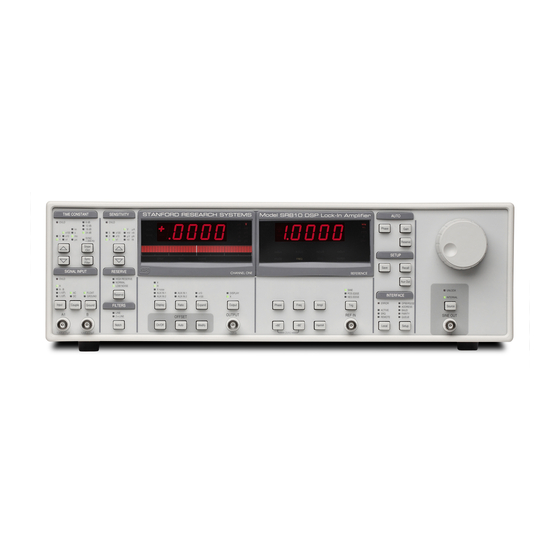
MODEL SR810
DSP Lock-In Amplifier
1290-D Reamwood Avenue
Sunnyvale, California 94089
Phone: (408) 744-9040 • Fax: (408) 744-9049
email: info@thinkSRS.com • www.thinkSRS.com
Copyright © 1993, 2000 by SRS, Inc.
All Rights Reserved.
Revision 1.8 (01/2005)
Advertisement
Table of Contents

Related Manuals for Stanford Research Systems SR810


Summary of Contents for Stanford Research Systems SR810
- Page 1 ® Advanced Test Equipment Rentals www.atecorp.com 800-404-ATEC (2832) MODEL SR810 DSP Lock-In Amplifier 1290-D Reamwood Avenue Sunnyvale, California 94089 Phone: (408) 744-9040 • Fax: (408) 744-9049 email: info@thinkSRS.com • www.thinkSRS.com Copyright © 1993, 2000 by SRS, Inc. All Rights Reserved.
-
Page 3: Table Of Contents
Command Syntax SR810 BASICS Interface Ready and Status What is a Lock-in Amplifier? GET (Group Execute Trigger) What Does a Lock-in Measure? The SR810 Functional Diagram DETAILED COMMAND LIST Reference Channel Reference and Phase Phase Sensitive Detectors Input and Filter... - Page 4 Table of Contents PERFORMANCE TESTS Self Tests DC Offset Common Mode Rejection Amplitude Accuracy and Flatness Amplitude Linearity Frequency Accuracy Phase Accuracy 6-10 Sine Output Amplitude 6-11 DC Outputs and Inputs 6-13 Input Noise 6-15 Performance Test Record 6-17 CIRCUITRY Circuit Boards CPU and Power Supply Board DSP Logic Board...
-
Page 5: Safety And Preparation For Use
LINE VOLTAGE SELECTION Contact the factory for instructions on how to return the instrument for authorized service and The SR810 operates from a 100V, 120V, 220V, or adjustment. 240V nominal AC power source having a line frequency of 50 or 60 Hz. Before connecting the... - Page 6 Symbols that may be found on SRS products Symbol Description Alternating current Caution - risk of electric shock Frame or chassis terminal Caution - refer to accompanying documents Earth (ground) terminal Battery Fuse On (supply) Off (supply)
-
Page 7: Specifications
SR810 DSP Lock In-Amplifier SPECIFICATIONS SIGNAL CHANNEL Voltage Inputs Single-ended (A) or differential (A-B). Current Input or 10 Volts/Amp. Full Scale Sensitivity 2 nV to 1 V in a 1-2-5-10 sequence (expand off). Input Impedance Voltage: 10 MΩ+25 pF, AC or DC coupled. - Page 8 SR810 DSP Lock In-Amplifier DISPLAYS Channel 1 4 1/2 digit LED display with 40 segment LED bar graph. X, R, X Noise, Aux Input 1 or 2. The display can also be any of these quantities divided by Aux Input 1 or 2.
-
Page 9: Command List
SR810 DSP Lock In-Amplifier COMMAND LIST VARIABLES i,j,k,l,m Integers Frequency (real) x,y,z Real Numbers String REFERENCE and PHASE page description PHAS (?) {x} Set (Query) the Phase Shift to x degrees. FMOD (?) {i} Set (Query) the Reference Source to External (0) or Internal (1). - Page 10 *RST 5-19 Reset the unit to its default configurations. *IDN? 5-19 Read the SR810 device identification string. LOCL(?) {i} 5-19 Set (Query) the Local/Remote state to LOCAL (0), REMOTE (1), or LOCAL LOCKOUT (2). OVRM (?) {i} 5-19 Set (Query) the GPIB Override Remote state to Off (0) or On (1).
- Page 11 SR810 DSP Lock In-Amplifier *SRE (?) {i} {,j} 5-20 Set (Query) the Serial Poll Enable Register to the decimal value i (0- 255). *SRE i,j sets bit i (0-7) to j (0 or 1). *SRE? queries the byte, *SRE?i queries only bit i.
- Page 12 SR810 DSP Lock In-Amplifier STATUS BYTE DEFINITIONS SERIAL POLL STATUS BYTE (5-21) LIA STATUS BYTE (5-23) name usage name usage No data is being acquired RSRV/INPT Set when on RESERVE or No command execution in INPUT overload progress FILTR Set when on FILTR overload...
-
Page 13: Getting Started
The sample measurements described in this section are designed to acquaint the first time user with the SR810 DSP Lock-In Amplifier. Do not be concerned that your measurements do not exactly agree with these exercises. The focus of these measurement exercises is to learn how to use the instrument. -
Page 14: The Basic Lock-In
The Basic Lock-in THE BASIC LOCK-IN This measurement is designed to use the internal oscillator to explore some of the basic lock-in functions. You will need BNC cables. Specifically, you will measure the amplitude of the Sine Out at various frequencies, sensitivities, time constants and phase shifts. - Page 15 The Basic Lock-in The internal oscillator is crystal synthesized with 25 Use the knob to adjust the frequency back ppm of frequency error. The frequency can be set with to 1 kHz. 4 1/2 digit or 0.1 mHz resolution, whichever is greater. 5.
- Page 16 The Basic Lock-in 11. Press [Sync Filter] This turns on synchronous filtering whenever the detection frequency is below 200 Hz. Synchronous filtering effectively removes output components at multiples of the detection frequency. At low frequencies, this filter is a very effective way to remove 2f without using extremely long time constants.
-
Page 17: And R
X and R X, Y, R and q This measurement is designed to use the internal oscillator and an external signal source to explore some of the display types. You will need a synthesized function generator capable of providing a 100 mVrms sine wave at 1.000 kHz (the DS335 from SRS will suffice), BNC cables and a terminator appropriate for the generator function output. - Page 18 X and R The phase (q) between the reference and the signal changes by 360° approximately every 5 sec (0.2 Hz difference frequency). The value of q can read via the computer interface. Press [Channel 1 Display] to select X again. Change the display back to X (slowly oscillating).
-
Page 19: Outputs, Offsets And Expands
Outputs, Offsets and Expands OUTPUTS, OFFSETS and EXPANDS This measurement is designed to use the internal oscillator to explore some of the basic lock-in outputs. You will need BNC cables and a digital voltmeter (DVM). Specifically, you will measure the amplitude of the Sine Out and provide analog outputs proportional to the measurement. - Page 20 The offset should be about 50%. Offsets are useful for making relative measurements. In analog lock-ins, offsets were generally used to remove DC output errors from the lock-in itself. The SR810 has no DC output errors and the offset is not required for most measurements.
- Page 21 Outputs, Offsets and Expands rear panel. voltages proportional to X and Y (with offset and expand). The X output voltage should be 10 V, just like the CH1 output. 7. Connect the DVM to the CH1 OUTPUT on The front panel outputs can be configured to output the front panel again.
-
Page 22: Storing And Recalling Setups
Storing and Recalling Setups STORING and RECALLING SETUPS The SR810 can store 9 complete instrument setups in non-volatile memory. 1. Turn the lock-in on while holding down the When the power is turned on with the [Setup] key [Setup] key. Wait until the power-on tests pressed, the lock-in returns to its standard settings. -
Page 23: Aux Outputs And Inputs
Aux Outputs and Inputs AUX OUTPUTS and INPUTS This measurement is designed to illustrate the use of the Aux Outputs and Inputs on the rear panel. You will need BNC cables and a digital voltmeter (DVM). Specifically, you will set the Aux Output voltages and measure them with the DVM. These outputs will then be connected to the Aux Inputs to simulate external DC voltages which the lock-in can measure. - Page 24 Aux Outputs and Inputs at a programmable sampling rate. This allows storage of not only the lock-in outputs, X or R, but also the values of Aux Inputs 1 or 2. See the Programming section for more details. 2-12...
- Page 25 Aux Outputs and Inputs 2-13...
-
Page 26: Sr810 Basics
) where V is the signal amplitude. Lock-in amplifiers use a technique known as The SR810 generates its own sine wave, shown phase-sensitive detection to single out the as the lock-in reference below. The lock-in t + θ component of the signal at a specific reference reference is V sin(ω... - Page 27 (with variable sine output and a TTL sync) which is always phase-locked to the A dual-phase lock-in, such as the SR810, has two reference oscillator. PSD's, with reference oscillators 90° apart, and can measure X, Y and R directly. In addition, the...
-
Page 28: What Does A Lock-In Measure
+ θ) are written as if θ is in 0.2546sin(5ωt) + ... radians mostly for simplicity. Lock-in amplifiers always manipulate measure phase where ω = 2πf. The SR810, locked to f will single degrees. out the first component. The measured signal will... -
Page 29: The Sr810 Functional Diagram
The functional block diagram of the SR810 DSP processor (DSP). We'll discuss the DSP aspects Lock-In Amplifier is shown below. The functions in of the SR810 as they come up in each functional the gray area are handled by the digital signal block description. -
Page 30: Reference Channel
This waveform is sin(ω Internal Oscillator 90°). The internal oscillator in the SR810 is basically a Both reference sine waves are calculated to 20 102 kHz function generator with sine and TTL bits of accuracy and a new point is calculated sync outputs. - Page 31 SR810 Basics but the instantaneous phase shift has a few Phase noise in the SR810 is very low and millidegrees of noise. This shows up at the output generally causes no problems. In applications as noise in phase or quadrature measurements.
-
Page 32: Phase Sensitive Detectors
Digital PSD vs Analog PSD numbers. The A/D converter used in the SR810 is The phase sensitive detectors (PSD's) in the extremely linear, meaning that the presence of SR810 act as linear multipliers, that is, they large noise signals does not impair its ability to multiply the signal with a reference sine wave. -
Page 33: Time Constants And Dc Gain
24 dB/oct of roll off. Since the filters are digital, the the signal and the reference) and the noise SR810 is not limited to just two stages of filtering. components. This filter is what makes the lock-in such a narrow band detector. - Page 34 Amplification is simply taking input and provides overall noise attenuation as well. numbers and multiplying by the gain. This allows the SR810 to operate with 100 dB of dynamic reserve without any output offset or zero drift. Long Time Constants...
-
Page 35: Dc Outputs And Scaling
The X and Y rear panel outputs are the outputs from the two phase sensitive detectors with low The SR810 has the ability to offset the X, Y and R pass filtering, offset and expand. These outputs outputs. This is useful when measuring deviations are the traditional outputs of an analog lock-in. - Page 36 The X and Y offset and expand functions in the will display a highlighted Expand indicator below SR810 are output functions, They do NOT the display. affect the calculation of R or θ. R has its own Ratio displays are displayed as percentages.
-
Page 37: Dynamic Reserve
SR810 Basics DYNAMIC RESERVE We've mentioned dynamic reserve quite a bit in at very high gain and low frequency noise and the preceding discussions. It's time to clarify offset drift at the PSD output or the DC amplifier dynamic reserve a bit. - Page 38 Why can't the SR810 run with lower reserve at this To set a scale, the SR810's output noise at 100 sensitivity? dB dynamic reserve is only measurable when the signal input is grounded.
-
Page 39: Signal Input Amplifier And Filters
0.16 % of full scale (7.9 nV/5 the signal to noise. The analog gain in the SR810 µV). The peak to peak noise will be about 0.8 % of ranges from roughly 7 to 1000. As discussed full scale. -
Page 40: Input Impedance
100 kHz and the sampling frequency is 256 kHz so things are ok. However, no signals The input impedance of the SR810 is 10 MΩ. If a above 128 kHz can be allowed to reach the A/D higher input impedance is desired, then the converter. -
Page 41: Input Connections
SR810 Basics INPUT CONNECTIONS In order to achieve the best accuracy for a given measurement, care must be taken to minimize the Differential Voltage Connection (A-B) various noise sources which can be found in the second method connection laboratory. With intrinsic noise (Johnson noise, 1/f differential mode. - Page 42 Signals far above the input bandwidth are Current Input (I) attenuated by 6 dB/oct. The noise and bandwidth The current input on the SR810 uses the A input are listed below. BNC. The current input has a 1 kΩ input...
-
Page 43: Intrinsic (Random) Noise Sources
The shot noise or current noise is given by Since the input signal amplifier in the SR810 has a bandwidth of approximately 300 kHz, the effective ½... - Page 44 SR810 Basics All of these noise sources are incoherent. The total random noise is the square root of the sum of Total noise the squares of all the incoherent noise sources. 3-19...
-
Page 45: External Noise Sources
SR810 Basics EXTERNAL NOISE SOURCES In addition to the intrinsic noise sources discussed For example, if the noise source is a power circuit, in the previously, there are a variety of external then f = 60 Hz and V = 120 V. C... - Page 46 SR810 Basics Cures for inductively coupled noise include: Microphonics Not all sources of noise are electrical in origin. 1) Removing or turning off the interfering Mechanical noise can be translated into electrical noise source. noise by microphonic effects. Physical changes in...
- Page 47 SR810 Basics potential of the first junction. This second temperature as the first junction. junction should be held at the same 3-22...
-
Page 48: Noise Measurements
The averaging time is selected by the SR810 and ranges from 10 to 80 times the time The ENBW is determined by the time constant and constant. Shorter averaging times yield a very slope as shown below. -
Page 49: Reset
Ref Input Sine Output Power The power switch is on the rear panel. The SR810 is turned on by pushing switch up. The serial number (5 digits) and the firmware version are shown in the displays at power on. A series of internal tests are performed at this point. -
Page 50: Local Lockout
Front Panel reference phase shift, sine output amplitude, harmonic detect number, offsets, Aux Output levels, and various Setup parameters. Local Lockout If the computer interface has placed the unit in the REMOTE state, indicated by the REMOTE led, then the keys and the knob are disabled. Attempts to change the settings from the front panel will display the message 'LOCL LOut' indicating local control is locked out by the interface. -
Page 51: Keypad Test
Front Panel the number of on LED's until all of the LED's are off. The SR810 is still operating, the output voltages are updated and the unit responds to interface commands. To change a setting, press any key other than... - Page 52 Front Panel STANDARD SETTINGS If the [Setup] key is held down when the power is turned on, the lock-in settings will be set to the defaults shown below rather than the settings that were in effect when the power was last turned off. The default settings may also be recalled using the *RST command over the computer interface.
-
Page 53: Signal Input And Filters
Front Panel Signal Input and Filters [Input] The [Input] key selects the front end signal input configuration. The input amplifier can be either a single-ended (A) or differential (A-B) voltage or a current (I). The voltage inputs have a 10 MΩ, 25 pF input impedance. Their connector shields are isolated from the chassis by either 10 Ω... - Page 54 10 Hz or so. If the reference frequency is 70 Hz, do not use the 60 Hz notch filter! The signal will be attenuated and the phase shifted. See the SR810 Basics section for a discussion of when these filters improve a measurement.
-
Page 55: Sensitivity, Reserve, Time Constants
This key selects the reserve mode, either Low Noise, Normal or High Reserve. The actual reserve (in dB) depends upon the sensitivity. When the reserve is High, the SR810 automatically selects the maximum reserve available at the present full scale sensitivity. When the reserve is Low, the minimum available reserve is selected. - Page 56 Do not use ultra high dynamic reserves above 120 dB unless absolutely necessary. It will be very likely that the noise floor of any interfering signal will obscure the signal at the reference and make detection difficult if not impossible. See the SR810 Basics section for more information. Auto Reserve Pressing [AUTO RESERVE] will change the reserve mode to the minimum reserve required.
- Page 57 Front Panel and the frequency increases above 200 Hz, the time constant WILL change to 30 s. Decreasing the frequency back below 200 Hz will NOT change the time constant back to 100 s. The absolute minimum time constant is 10 µs. The actual minimum time constant depends upon the filter slope and the DC gain in the low pass filter (dynamic reserve plus expand).
- Page 58 (ENBW) of the low pass filter. This is the measurement bandwidth for X and Y noise and depends upon the time constant and filter slope. (See the Noise discussion in the SR810 Basics section.) FILTER OVLD The OVLD led in the Time Constant section indicates that the low pass filters have overloaded.
- Page 59 The synchronous filter does NOT attenuate broadband noise (except at the harmonic frequencies). The low pass filters remove outputs due to noise and interfering signals. See the SR810 Basics section for a discussion of time constants and filtering. Note: The synchronous filter averages the outputs over a complete period.
-
Page 60: Ch1 Display And Output
The bar graph is ±full scale sensitivity for X, R and X Noise, and ±10V for the Aux Inputs. Ratio displays are shown in % and the bar graph is scaled to ±100%. See the SR810 Basics section for a complete discussion of scaling. - Page 61 If the display is showing a quantity which is affected by an offset or a non-unity expand, then the Offset and Expand indicators are turned on below the display. See the SR810 Basics section for a complete discussion of scaling, offsets and expands. [Offset On/Off] Pressing this key turns the X or R offset (as selected by the [Display] key) on or off.
- Page 62 Front Panel Reference Display to its original display, press the desired reference display key ([Phase], [Freq], [Ampl], [Harm #] or [Aux Out]). [Auto Offset] Pressing this key automatically sets the X or R offset percentage to offset the selected output quantity to zero. [Expand] Pressing this key selects the X and R Expand.
-
Page 63: Reference
Front Panel Reference UNLOCK The UNLOCK indicator turns on if the SR810 can not lock to the external reference. TRIG The TRIG indicator flashes whenever a trigger is received at the rear panel trigger input AND internal data storage is triggered. - Page 64 [Harm #] The SR810 can detect signals at harmonics of the reference frequency. The SR810 multiplies the input signal with digital sine waves at a multiple of the reference. Only signals at this harmonic will be detected. Signals at the original reference frequency are not detected and are attenuated as if they were noise.
- Page 65 102 kHz/N. If an external reference is used and the reference frequency exceeds 102 kHz/N, then N is reset to 1. The SR810 will always track the external reference. Pressing this key displays the harmonic number in the Reference display.
-
Page 66: Auto Functions
Front Panel Auto Functions Pressing an Auto Function key initiates an auto function which may take some time. The AUTO led in the CH1 display will be on while the function is in progress. A multi-tone sound will indicate when the auto function is complete and the AUTO leds will turn off. - Page 67 There is no truly reliable way to automatically setup a lock-in amplifier for all possible input signals. In most cases, the following procedure should setup the SR810 to measure the input signal. 1. Press [AUTO GAIN] to set the sensitivity.
-
Page 68: Setup
Front Panel Setup [Save] Nine amplifier setups may be stored in non-volatile memory.To save a setup, press [Save] to display the buffer number (1..9) in the Reference display. Use the knob to select the desired buffer number. Press [Save] again to store the setup in the buffer, or any other key to abort the save process. -
Page 69: Interface
Setup. GPIB/SR-232 The SR810 only outputs data to one interface at a time. Commands may be received over both interfaces but responses are directed only to the selected interface. Make sure that the selected interface is set correctly before attempting to program the SR810 from a computer. - Page 70 No front panel adjustments may be made. This indicator is on whenever a GPIB Service Request is generated by the SR810. SRQ stays on until a serial poll is completed. ACTIVE This indicator flashes when there is activity on the computer interface.
-
Page 71: Warning Messages
Front Panel WARNING MESSAGES The SR810 displays various warning messages whenever the operation of the instrument is not obvious. The two tone warning alarm sounds when these messages are displayed. Display Warning Message Meaning LOCL LOut LOCAL LOCKOUT If the computer interface has placed the unit in the REMOTE state, indicated by the REMOTE led, then the keys and the knob are disabled. -
Page 72: Rear Panel
The RS-232 interface connector is configured as a DCE (transmit on pin 3, receive on pin 2). The baud rate and parity are programmed with the [Setup] key. To connect the SR810 to a PC serial adapter, which is usually a DTE, use a straight thru serial cable. -
Page 73: Preamp Connector
1, 10 or 100. The X offset and expand are set from the front panel. The Y offset and expand may only be set from the interface. Overloads on Y are not reported by the SR810. MONITOR OUT This BNC provides a buffered output from the signal amplifiers and prefilters. -
Page 74: Using Srs Preamps
SR810. Use BNC cables to connect the A output from the preamp to the A input of the SR810. The B output from the preamp (preamp ground) may be connected to the B input of the SR810. In this case, use A-B as the input configuration. -
Page 75: Communications
COMMUNICATING WITH RS-232 232. Commands may require one or more parameters. Multiple parameters are separated by The SR810 is configured as a DCE ( transmit on commas (,). pin 3, receive on pin 2) device and supports CTS/DTR hardware handshaking. The CTS signal... -
Page 76: Interface Ready And Status
Remote Programming Values returned by the SR810 are sent as a string Ready bit is set again and new commands will be of ASCII characters terminated by a carriage processed. Since most commands execute very return <cr> on RS-232 and by a line-feed <lf> on quickly, the host computer does not need to GPIB. -
Page 77: Detailed Command List
Remote Programming DETAILED COMMAND LIST The four letter mnemonic in each command sequence specifies the command. The rest of the sequence consists of parameters. Multiple parameters are separated by commas. Parameters shown in { } are optional or may be queried while those not in { } are required. Commands that may be queried have a question mark in parentheses (?) after the mnemonic. -
Page 78: Reference And Phase
Remote Programming REFERENCE and PHASE COMMANDS PHAS (?) {x} The PHAS command sets or queries the reference phase shift. The parameter x is the phase (real number of degrees). The PHAS x command will set the phase shift to x. The value of x will be rounded to 0.01°. -
Page 79: Input And Filter
Remote Programming INPUT and FILTER COMMANDS ISRC (?) {i} The ISRC command sets or queries the input configuration. The parameter i selects A (i=0), A-B (i=1), I (1 MΩ) (i=2) or I (100 MΩ) (i=3). Changing the current gain does not change the instrument sensitivity. Sensitivities above 10 nA require a current gain of 1 MΩ. -
Page 80: Gain And Time Constant
Remote Programming GAIN and TIME CONSTANT COMMANDS SENS (?) {i} The SENS command sets or queries the sensitivity. The parameter i selects a sensitivity below. sensitivity sensitivity 2 nV/fA 50 µV/pA 5 nV/fA 100 µV/pA 10 nV/fA 200 µV/pA 20 nV/fA 500 µV/pA 50 nV/fA 1 mV/nA... - Page 81 Remote Programming SYNC (?) {i} The SYNC command sets or queries the synchronous filter status. The parameter i selects Off (i=0) or synchronous filtering below 200 Hz (i=1). Synchronous filtering is turned on only if the detection frequency (reference x harmonic number) is less than 200 Hz.
-
Page 82: Display And Output
The Y offset and expand may only be set using the OEXP command. The Yoffset and expand only affect the rear panel Y output. Overloads on Y are not reported by the SR810. AOFF i The AOFF i command automatically offsets X (i=1), Y (i=2) or R (i=3) to zero. -
Page 83: Aux Input And Output
Remote Programming AUX INPUT and OUTPUT COMMANDS OAUX? i The OAUX? command queries the Aux Input values. The parameter i selects an Aux Input (1, 2, 3 or 4) and is required. The Aux Input voltages are returned as ASCII strings with units of Volts. The resolution is 1/3 mV. -
Page 84: Setup
OVRM i In general, every GPIB interface command will put the SR810 into the REMOTE state with the front panel deactivated. To defeat this feature, use the OVRM 1 command to override the GPIB remote. In this mode, the front panel is not locked out when the unit is in the REMOTE state. -
Page 85: Auto Functions
Remote Programming AUTO FUNCTIONS AGAN The AGAN command performs the Auto Gain function. This command is the same as pressing the [Auto Gain] key. Auto Gain may take some time if the time constant is long. AGAN does nothing if the time constant is greater than 1 second. -
Page 86: Data Storage
Data Storage The SR810 can store up to 8191 points from the Channel 1 display in an internal data buffer. The data buffer is NOT retained when the power is turned off. The data buffer is accessible only via the computer interface. - Page 87 Remote Programming Aliasing Effects In any sampled data stream, it is possible to sample a high frequency signal such that it will appear to be a much lower frequency. This is called aliasing. For example, suppose the lock-in is detecting a signal near 1 Hz with a relatively short time constant. The X output will have a DC component and a 2 Hz component (2xf).
- Page 88 Remote Programming STRT The STRT command starts or resumes data storage. STRT is ignored if storage is already in progress. PAUS The PAUS command pauses data storage. If storage is already paused or reset then this command is ignored. REST The REST command resets the data buffers.
-
Page 89: Data Transfer
Remote Programming DATA TRANSFER COMMANDS The OUTP? i command reads the value of X, Y, R or θ. The parameter OUTP ? i i selects X (i=1), Y (i=2), R (i=3) or q (i=4). Values are returned as ASCII floating point numbers with units of Volts or degrees. For example, the response might be "-1.01026". - Page 90 Remote Programming The SNAP? command is a query only command. The SNAP? command is used to record various parameters simultaneously, not to transfer data quickly. OAUX? i The OAUX? command reads the Aux Input values. The parameter i selects an Aux Input (1, 2, 3 or 4) and is required. The Aux Input voltages are returned as ASCII strings with units of Volts.
- Page 91 = m x 2 where m is the mantissa and exp is the exponent. The data within the SR810 is stored in this format. Data transfers using this format are faster than IEEE floating point format. If data transfer speed is important, the TRCL? command should be used.
-
Page 92: Interface
At fast sample rates, it is important that the receiving interface be able to keep up. If the SR810 finds that the interface is not ready to receive a point, then the fast transfer mode is turned off. - Page 93 Remote Programming STRD After using FAST1 or FAST 2 to turn on fast data transfer, use the STRD command to start the data storage. STRD starts data storage after a delay of 0.5 sec. This delay allows the controlling interface to place itself in the read mode before the first data points are transmitted.
- Page 94 LOCL (?) {i} The LOCL command sets the local/remote function. If i=0 the SR810 is LOCAL, if i=1 the SR810 will go REMOTE, and if i=2 the SR810 will go into LOCAL LOCKOUT state. The states duplicate the GPIB local/remote states.
-
Page 95: Status Reporting
Remote Programming STATUS REPORTING COMMANDS The Status Byte definitions follow this section. *CLS The *CLS command clears all status registers. The status enable registers are NOT cleared. *ESE (?) {i} {,j} The *ESE i command sets the standard event enable register to the decimal value i (0-255). - Page 96 Remote Programming LIAS? i command queries the value (0 or 1) of bit i (0-7). Reading the entire byte will clear it while reading bit i will clear just bit i. 5-22...
-
Page 97: Status Byte Definitions
Remote Programming STATUS BYTE DEFINITIONS The SR810 reports on its status by means of four status bytes: the Serial Poll Status byte, the Standard Event Status byte, the LIA Status byte, and the Error Status byte. The status bits are set to 1 when the event or state described in the tables below has occurred or is present. -
Page 98: Service Requests
Remote Programming SERVICE REQUESTS (SRQ) A GPIB service request (SRQ) will be generated whenever a bit in both the Serial Poll Status byte AND Serial Poll Enable register is set. Use SSRE to set bits in the Serial Poll Enable register. A service request is only generated when an enabled Serial Poll Status bit becomes set (changes from 0 to 1). -
Page 99: Lia Status Byte
Remote Programming LIA STATUS BYTE name usage INPUT/RESRV Set when an Input or Amplifier overload is detected. FILTR Set when a Time Constant filter overload is detected. OUTPT Set when an Output overload is detected. UNLK Set when a reference unlock is detected. RANGE Set when the detection frequency switches ranges (harmonic x ref. - Page 100 Remote Programming 5-26...
-
Page 101: Example Program
[Setup] key. The default GPIB address is 8; use this address unless a conflict occurs with other instruments in your system. The SR810 will be set to GPIB address 8 whenever a reset is performed (power on with the [Setup] key down). - Page 102 <devName>\n"); exit(1); else initGpib(SR810); txLia("OUTX1"); /* Set the SR810 to output responses to the GPIB port */ setupLia(); /* Setup the SR810 */ printf("\nAcquiring Data\n"); ibtmo(lia,0); /* turn off timeout for lia or set the timeout longer than the scan (10 seconds).
- Page 103 /* format and print results */ printf ("End of Program"); void printOutBinaryResults(void) /* calculates the first 10 values of R based on the X and Y values taken in FAST mode by the SR810 */ int i; float x,y,r; int *ptr;...
- Page 104 (i=0;i<10;i++) printf("%d %e\n",i,rfBuf[i]); /* this is simple since the values are already IEEE floats */ void printOutLIAResults(void) /* calculates the first 10 values of R transferred in LIA float format by the SR810 */ int i,mant,exp; int *ptr; float val;...
-
Page 105: Using Sr510 Programs
SR810 commands in order to take advantage of all of the SR810 features. The SR565 program will NOT run reliably with the SR810. This is because the SR565 is optimized for speed and the SR810 command execution time for some commands is longer than in the SR510. - Page 106 Amps. R {n} Change the reference input mode. S {n} Change the Output displays. The SR810 only responds if n=0 (X) or n=2 (Xnoise). T m {,n} Change the time constant. If m=1, then T1,n sets the time constant from 1 ms (n=1) to 30 ks (n=16).
- Page 107 V {n} Change the value of the SRQ mask. This command changes the serial poll enable register of the SR810. The serial poll byte is that of the SR810 not the SR510! Programs which query the SR510 status need to be changed to query the equivalent SR810 status byte.
- Page 108 Remote Programming 5-34...
-
Page 109: Introduction
Test Record Make a copy of the SR810 Performance Test Record at the end of this section. Fill in the results of the tests on this record. This record will allow you to determine whether the tests pass or fail and also to preserve a record of the tests. -
Page 110: Front Panel Display Test
Performance Tests Recommended SRS DS335 2. AC Calibrator Freq Range 10 Hz to 100 kHz Amplitude 1 mV to 10 V Accuracy 0.1 % External phase locking capability Recommended Fluke 5200A 3. DC Voltmeter Range 19.999 V, 4½ digits Accuracy 0.005 % Recommended Fluke 8840A... -
Page 111: Self Tests
Performance Tests 1. Self Tests The self tests check the lock-in hardware. These are functional tests and do not relate to the specifications. These tests should be checked before any of the performance tests. Setup No external setup is required for this test. Procedure 1) {PRESET} (Turn on the lock-in with the [Setup] key pressed) Check the results of the DATA, BATT, PROG and DSP tests. -
Page 112: Dc Offset
Performance Tests 2. DC Offset This test measures the DC offset of the input. Setup Connect a 50• terminator to the A input. This shorts the input so the lock-in's own DC offset will be measured. Procedure 1) {PRESET} (Turn the lock-in off and on with the [Setup] key pressed) 2) Press the keys in the following sequence: [Freq] Use the knob to set the frequency to 1.00 Hz. -
Page 113: Common Mode Rejection
Performance Tests 3. Common Mode Rejection This test measures the common mode rejection of the lock-in. Setup We will use the internal oscillator sine output to provide the signal. Connect the Sine Out to both the A and B inputs of the lock-in. Use equal length cables from A and B to a BNC TEE. -
Page 114: Amplitude Accuracy And Flatness
Performance Tests 4. Amplitude Accuracy and Flatness This test measures the amplitude accuracy and frequency response. Setup We will use the frequency synthesizer to provide an accurate frequency and the AC calibrator to provide a sine wave with an exact amplitude. Connect the output of the frequency synthesizer to the phase lock input of the calibrator. - Page 115 Performance Tests c) Wait for the R reading to stabilize. Record the value of R for each sensitivity. 4) Frequency response is checked at frequencies above 1 kHz. The test frequencies are listed below. Test Frequencies 24 kHz 48 kHz 72 kHz 96 kHz a) Set the AC calibrator to 1 kHz and an amplitude of 200.00 mVrms.
-
Page 116: Amplitude Linearity
Performance Tests 5. Amplitude Linearity This test measures the amplitude linearity. This tests how accurately the lock-in measures a signal smaller than full scale. Setup We will use the frequency synthesizer to provide an accurate frequency and the AC calibrator to provide a sine wave with an exact amplitude. -
Page 117: Frequency Accuracy
Performance Tests 6. Frequency Accuracy This test measures the frequency accuracy of the lock-in. This tests the accuracy of the frequency counter inside the unit. The counter is used only in external reference mode. The internal oscillator frequency is set by a crystal and has 25 ppm frequency accuracy. -
Page 118: Phase Accuracy
Performance Tests 7. Phase Accuracy This test measures the phase accuracy of the lock-in. Due to the design of the lock-in, the phase accuracy can be determined by measuring the phase of the internal oscillator Sine Out. Setup Connect the Sine Out to the A input of the lock-in using a 1 meter BNC cable. Do not use any termination. Procedure 1) {PRESET} (Turn the lock-in off and on with the [Setup] key pressed) 2) Press the keys in the following sequence:... -
Page 119: Sine Output Amplitude
Performance Tests 8. Sine Output Amplitude Accuracy and Flatness This test measures the amplitude accuracy and frequency response of the internal oscillator Sine Out. Setup We will use the lock-in to measure the Sine Out. Connect the Sine Out to the A input of the lock-in. Procedure 1) {PRESET} (Turn the lock-in off and on with the [Setup] key pressed) 2) Press the keys in the following sequence:... - Page 120 Performance Tests [Freq] Use the knob to set the internal oscillator frequency to the value in the table. e) Wait for the R reading to stabilize. Record the value of R. f) Repeat steps 4d and 4e for all of the frequencies listed. 5) This completes the sine output amplitude accuracy and frequency response test.
-
Page 121: Dc Outputs And Inputs
Performance Tests 9. DC Outputs and Inputs This test measures the DC accuracy of the DC outputs and inputs of the lock-in. Setup We will use the digital voltmeter (DVM) to measure the DC outputs of the lock-in. Then we will use one of the outputs to generate a voltage to measure on the DC inputs. - Page 122 Performance Tests d) Use the knob to adjust the Aux Output level to the value from the table. e) Record the DVM reading. 4) Press [Aux Out] Display Aux Out 1 on the Reference display. 5) For Aux Inputs 1 and 2, repeat steps 5a through 5e. a) Connect Aux Out 1 to Aux Input 1 (or 2) with a BNC cable.
-
Page 123: Input Noise
Performance Tests 10. Input Noise This test measures the lock-in input noise. Setup Connect a 50 Ω termination to the A input. This grounds the input so the lock-in's own noise is measured. Procedure 1) {PRESET} (Turn the lock-in off and on with the [Setup] key pressed) 2) Press the keys in the following sequence: [Sensitivity Down] Set the sensitivity to 100 nV. - Page 124 Performance Tests 6-16...
-
Page 125: Performance Test Record
Performance Tests SR810 Performance Test Record Serial Number Tested By Firmware Revision Date Equipment Used 1. Self Tests Test Pass Fail DATA ____ ____ BATT ____ ____ PROG ____ ____ ____ ____ 2. DC Offset Input Coupling Reading Upper Limit _______ 0.500 mV... - Page 126 Performance Tests SR810 Performance Test Record 5. Amplitude Linearity Sensitivity Calibrator Ampl. Lower Limit Reading Upper Limit 1.0000 Vrms 0.9900 V _______ 1.0100 V 100.00 mVrms 0.0990 V _______ 0.1010 V 10.000 mVrms 0.0098 V _______ 0.0102 V 6. Frequency Accuracy...
- Page 127 Performance Tests SR810 Performance Test Record 9. DC Outputs and Inputs (continued) Output Voltage Lower Limit Reading Upper Limit AUX OUT 1 -10.000 -10.040 V _______ -9.960 V -5.000 -5.040 V _______ -4.960 V 0.000 -0.020 V _______ 0.020 V 5.000...
- Page 128 Performance Tests 6-20...
-
Page 129: Circuit Boards
Display Board Keypad Board CIRCUIT BOARDS CAUTION The SR810 has five main printed circuit boards. Always disconnect the power cord and wait The five boards shown contain most of the active at least one minute before opening the unit. circuitry of the unit. The rear panel circuit board... - Page 130 Circuit Description...
-
Page 131: Cpu And Power Supply Board
Circuit Description CPU and POWER SUPPLY BOARD The CPU board contains the microprocessor SPIN KNOB system. All display, front panel, disk, and computer interfaces are on this board. The knob is an optical encoder buffered by U612. Each transition of its outputs is clocked into U610 MICROPROCESSOR SYSTEM or U611 and generates an interrupt at the output of U602A. - Page 132 Circuit Description Always disconnect the power cord and wait at POWER SUPPLY REGULATORS least one minute before opening the unit. Check the LED at the front edge of the power The voltage regulators provide outputs at +5 V, supply board. The unit is safe only if the LED -5 V, ±15 V, and ±12 V.
-
Page 133: Dsp Logic Board
TIMING GENERATOR DSP PROCESSOR All timing signals for the DSP and Analog boards The SR810 utilizes a Motorola 24-bit DSP56001 are derived from the system clock by PALs (U601- digital signal processor (U501). The DSP is 604). These PALs generate the clocks for the configured without external memory. - Page 134 Circuit Description DAC via a pair of parallel-to-serial registers (U504 I/O INTERFACE TO CPU BOARD and U505). DAC OUTPUTS The I/O interface provides the communication pathway between the DSP Logic Board and the Three of the DAC output channels provide Sine main CPU Board.
-
Page 135: Analog Input Board
8-zero 9-pole elliptical low critical stage in the entire signal path. The design pass filter. The pass band of this filter is DC to of the front end input amplifier in the SR810 was 102 kHz. The stopband begins at 154 kHz. driven... - Page 136 Circuit Description Aux A/D inputs. The Aux inputs are multiplexed so that each input is read every four cycles. The two digital output streams are buffered by U406 and sent to the DSP board. I/O INTERFACE The Analog Input Board communicates with the CPU Board via its I/O Interface.
-
Page 137: Cpu And Power Supply Board
SR810 Parts List CPU and Power Supply Board Parts List Ref. SRS Part No. Value Description BT701 6-00001-612 BR-2/3A 2PIN PC Battery 5-00124-526 5600U Capacitor, Electrolytic, 35V, 20%, Rad 5-00124-526 5600U Capacitor, Electrolytic, 35V, 20%, Rad 5-00228-526 15000U Capacitor, Electrolytic, 35V, 20%, Rad... - Page 138 Circuit Description Ref. SRS Part No. Value Description C 1019 5-00225-548 .1U AXIAL Capacitor, Ceramic, 50V,+80/-20% Z5U AX C 1021 5-00225-548 .1U AXIAL Capacitor, Ceramic, 50V,+80/-20% Z5U AX C 1022 5-00225-548 .1U AXIAL Capacitor, Ceramic, 50V,+80/-20% Z5U AX C 1023 5-00100-517 2.2U Capacitor, Tantalum, 35V, 20%, Rad...
- Page 139 SR810 Parts List Ref. SRS Part No. Value Description JP903 1-00016-160 RS232 25 PIN D Connector, D-Sub, Right Angle PC, Female JP1000 1-00170-130 26 PIN ELH Connector, Male 0-00772-000 1.5" WIRE Hardware, Misc. LS701 6-00096-600 MINI Misc. Components N 101...
- Page 140 Circuit Description Ref. SRS Part No. Value Description 3-00119-329 7905 Voltage Reg., TO-220 (TAB) Package 3-00346-329 7812 Voltage Reg., TO-220 (TAB) Package 3-00330-329 7912 Voltage Reg., TO-220 (TAB) Package 3-00149-329 LM317T Voltage Reg., TO-220 (TAB) Package U 10 3-00141-329 LM337T Voltage Reg., TO-220 (TAB) Package U 101 3-00354-360...
-
Page 141: Dsp Logic Board
SR810 Parts List DSP Logic Board Parts List Ref. SRS Part No. Value Description C 101 5-00060-512 1.0U Cap, Stacked Metal Film 50V 5% -40/+85c C 114 5-00100-517 2.2U Capacitor, Tantalum, 35V, 20%, Rad C 117 5-00100-517 2.2U Capacitor, Tantalum, 35V, 20%, Rad... - Page 142 Circuit Description Ref. SRS Part No. Value Description C 280 5-00038-509 Capacitor, Electrolytic, 50V, 20%, Rad C 281 5-00038-509 Capacitor, Electrolytic, 50V, 20%, Rad C 282 5-00100-517 2.2U Capacitor, Tantalum, 35V, 20%, Rad C 283 5-00100-517 2.2U Capacitor, Tantalum, 35V, 20%, Rad C 290 5-00023-529 Cap, Monolythic Ceramic, 50V, 20%, Z5U...
- Page 143 SR810 Parts List Ref. SRS Part No. Value Description C 433 5-00219-529 .01U Cap, Monolythic Ceramic, 50V, 20%, Z5U C 434 5-00023-529 Cap, Monolythic Ceramic, 50V, 20%, Z5U C 435 5-00219-529 .01U Cap, Monolythic Ceramic, 50V, 20%, Z5U C 450...
- Page 144 Circuit Description Ref. SRS Part No. Value Description K 201 3-00444-335 BS-211-DC5 GF Relay L 101 6-00107-606 .8UH Inductor, Variable L 601 6-00006-602 Inductor, Radial N 101 4-00693-421 270X5 Res. Network, SIP, 1/4W,2% (Isolated) N 102 4-00690-421 3.3KX4 Res. Network, SIP, 1/4W,2% (Isolated) N 201 4-00693-421 270X5...
- Page 145 SR810 Parts List Ref. SRS Part No. Value Description R 173 4-00292-401 1.1K Resistor, Carbon Film, 1/4W, 5% R 174 4-00021-401 1.0K Resistor, Carbon Film, 1/4W, 5% R 175 4-00398-407 499K Resistor, Metal Film, 1/8W, 1%, 50PPM R 176 4-00130-407 1.00K...
- Page 146 Circuit Description Ref. SRS Part No. Value Description R 385 4-00795-412 Resistor, Carbon Film 1/2W 5% R 386 4-00795-412 Resistor, Carbon Film 1/2W 5% R 387 4-00215-407 Resistor, Metal Film, 1/8W, 1%, 50PPM R 388 4-00215-407 Resistor, Metal Film, 1/8W, 1%, 50PPM R 389 4-00706-407 Resistor, Metal Film, 1/8W, 1%, 50PPM...
- Page 147 SR810 Parts List Ref. SRS Part No. Value Description U 106 3-00402-340 74HC4052 Integrated Circuit (Thru-hole Pkg) U 107 3-00461-340 OPA2604 Integrated Circuit (Thru-hole Pkg) U 110 3-00437-340 AD9696KN Integrated Circuit (Thru-hole Pkg) U 111 6-00110-621 30.208 MHZ Crystal Oscillator...
- Page 148 Circuit Description Ref. SRS Part No. Value Description U 622 3-00491-340 UPD71054C Integrated Circuit (Thru-hole Pkg) U 623 3-00036-340 74HC00 Integrated Circuit (Thru-hole Pkg) U 630 3-00049-340 74HC74 Integrated Circuit (Thru-hole Pkg) 0-00012-007 TO-220 Heat Sinks 0-00043-011 4-40 KEP Nut, Kep 0-00373-000 CARD EJECTOR Hardware, Misc.
- Page 149 SR810 Parts List Ref. SRS Part No. Value Description C 371 5-00148-545 1000P - 50V Capacitor, Monolythic Ceramic, COG, 1% C 372 5-00148-545 1000P - 50V Capacitor, Monolythic Ceramic, COG, 1% C 381 5-00148-545 1000P - 50V Capacitor, Monolythic Ceramic, COG, 1%...
- Page 150 Circuit Description Ref. SRS Part No. Value Description D 481 3-00004-301 1N4148 Diode J 101 0-00388-000 RCA PHONO Hardware, Misc. J 102 0-00388-000 RCA PHONO Hardware, Misc. JP201 1-00006-130 2 PIN DI Connector, Male JP221 1-00006-130 2 PIN DI Connector, Male JP401 1-00184-130 32 PIN DIL...
- Page 151 SR810 Parts List Ref. SRS Part No. Value Description R 127 4-00142-407 100K Resistor, Metal Film, 1/8W, 1%, 50PPM R 129 4-00130-407 1.00K Resistor, Metal Film, 1/8W, 1%, 50PPM R 130 4-00192-407 49.9K Resistor, Metal Film, 1/8W, 1%, 50PPM R 131...
- Page 152 Circuit Description Ref. SRS Part No. Value Description R 313 4-00475-407 2.61K Resistor, Metal Film, 1/8W, 1%, 50PPM R 314 4-00748-408 2.000K Resistor, Metal Film, 1/8W, 0.1%, 25ppm R 315 4-00748-408 2.000K Resistor, Metal Film, 1/8W, 0.1%, 25ppm R 321 4-00467-407 2.43K Resistor, Metal Film, 1/8W, 1%, 50PPM...
- Page 153 SR810 Parts List Ref. SRS Part No. Value Description R 460 4-00030-401 Resistor, Carbon Film, 1/4W, 5% R 461 4-00030-401 Resistor, Carbon Film, 1/4W, 5% R 462 4-00030-401 Resistor, Carbon Film, 1/4W, 5% R 463 4-00030-401 Resistor, Carbon Film, 1/4W, 5%...
- Page 154 Circuit Description Ref. SRS Part No. Value Description U 180 3-00118-325 78L15 Transistor, TO-92 Package U 181 3-00124-325 79L15 Transistor, TO-92 Package U 201 3-00461-340 OPA2604 Integrated Circuit (Thru-hole Pkg) U 202 3-00385-340 74HC4053 Integrated Circuit (Thru-hole Pkg) U 203 3-00423-340 5534A Integrated Circuit (Thru-hole Pkg)
-
Page 155: Front Panel Display Board
SR810 Parts List Front Panel Display Board Parts List Ref. SRS Part No. Value Description 3-00546-340 HDSP-4830 Integrated Circuit (Thru-hole Pkg) 3-00546-340 HDSP-4830 Integrated Circuit (Thru-hole Pkg) 3-00546-340 HDSP-4830 Integrated Circuit (Thru-hole Pkg) 3-00546-340 HDSP-4830 Integrated Circuit (Thru-hole Pkg) 5-00023-529... - Page 156 Circuit Description Ref. SRS Part No. Value Description 3-00547-310 RED COATED LED, Coated Rectangular 3-00547-310 RED COATED LED, Coated Rectangular 3-00547-310 RED COATED LED, Coated Rectangular D 10 3-00547-310 RED COATED LED, Coated Rectangular D 11 3-00547-310 RED COATED LED, Coated Rectangular D 12 3-00547-310 RED COATED...
- Page 157 SR810 Parts List Ref. SRS Part No. Value Description D 73 3-00575-311 GREEN MINI LED, Subminiature D 74 3-00575-311 GREEN MINI LED, Subminiature D 75 3-00576-311 RED MINI LED, Subminiature D 76 3-00575-311 GREEN MINI LED, Subminiature D 77 3-00575-311...
- Page 158 N 12 4-00494-421 220X3 Res. Network, SIP, 1/4W,2% (Isolated) N 13 4-00263-425 1.0KX7 Resistor Network SIP 1/4W 2% (Common) 7-00529-701 SR810 DISPLAY Printed Circuit Board 7-00514-701 SR830 RP INPUT Printed Circuit Board 3-00264-340 MPQ3467 Integrated Circuit (Thru-hole Pkg) 3-00264-340 MPQ3467...
- Page 159 SR810 Parts List Ref. SRS Part No. Value Description U 19 3-00289-340 HDSP-H107 Integrated Circuit (Thru-hole Pkg) U 20 3-00288-340 HDSP-H101 Integrated Circuit (Thru-hole Pkg) U 21 3-00288-340 HDSP-H101 Integrated Circuit (Thru-hole Pkg) U 22 3-00288-340 HDSP-H101 Integrated Circuit (Thru-hole Pkg)
-
Page 160: Miscellaneous And Chassis Assembly
SR830-12 Fabricated Part 7-00506-720 SR830-14 Fabricated Part 7-00507-709 SR810/830 RP Lexan Overlay 7-00510-720 SR830-18/SR810 Fabricated Part 7-00513-701 SR810/830 AB IN Printed Circuit Board 7-00515-720 RCK MT (5.25") Fabricated Part 7-00527-709 SR810-6 Lexan Overlay 7-00528-701 SR810 KEYPAD Printed Circuit Board 7-00530-740... - Page 161 SR810 Parts List Ref. SRS Part No. Value Description 0-00185-021 6-32X3/8PP Screw, Panhead Phillips 0-00187-021 4-40X1/4PP Screw, Panhead Phillips 0-00204-000 REAR FOOT Hardware, Misc. 0-00248-026 10-32X3/8TRUSSP Screw, Black, All Types 0-00315-021 6-32X7/16 PP Screw, Panhead Phillips 7-00147-720 BAIL Fabricated Part...
Need help?
Do you have a question about the SR810 and is the answer not in the manual?
Questions and answers