Table of Contents
Advertisement
Quick Links
30-240
20" Floor Drill Press
Operator's Manual
Record the serial number and date of purchase in your manual for future reference.
Serial Number: _________________________
Date of purchase: _________________________
For technical support or parts questions, email techsupport@rikontools.com or call toll free at (877)884-5167
www.rikontools.com
30-240M4
Advertisement
Table of Contents

Related Manuals for Rikon Power Tools 30-240


Summary of Contents for Rikon Power Tools 30-240
- Page 1 30-240 20” Floor Drill Press Operator’s Manual Record the serial number and date of purchase in your manual for future reference. Serial Number: _________________________ Date of purchase: _________________________ For technical support or parts questions, email techsupport@rikontools.com or call toll free at (877)884-5167 www.rikontools.com...
-
Page 2: Table Of Contents
TABLE OF CONTENTS Specifications........................2 Safety Instructions ......................3 - 6 Contents of Package .....................7 Getting To Know Your Machine ....................8 Installation ........................8 Assembly ........................9 - 12 Adjustments.......................12 - 15 Operation .......................15 Maintenance ........................16 Electricals & Wiring Diagram ..................5 & 16 Troubleshooting ......................17 Parts Diagrams ......................18 - 20 Parts List ........................21... -
Page 3: Safety Instructions
SAFETY INSTRUCTIONS IMPORTANT! Safety is the single most important consideration in the operation of this equipment. The following instructions must be followed at all times. Failure to follow all instructions listed below may result in electric shock, fire, and/or serious personal injury. There are certain applications for which this tool was designed. - Page 4 SAFETY INSTRUCTIONS 12. KEEP PROTECTIVE GUARDS IN PLACE AND IN 25. ALWAYS WEAR A DUST MASK TO PREVENT WORKING ORDER. INHALING DANGEROUS DUST OR AIRBORNE PARTICLES, including wood dust, crystalline silica dust 13. AVOID ACCIDENTAL STARTING. Make sure that and asbestos dust. Direct particles away from face and the power switch is in the “OFF”...
-
Page 5: Electricals & Wiring Diagram
SAFETY INSTRUCTIONS EXTENSION CORDS ELECTRICAL SAFETY THE USE OF AN EXTENSION CORD THIS TOOL MUST BE GROUNDED WITH THIS MACHINE IS NOT RECOMMENDED. For WHILE IN USE TO PROTECT THE OPERATOR FROM best power and safety, plug the machine directly into a ELECTRIC SHOCK. - Page 6 SAFETY INSTRUCTIONS SPECIFIC SAFETY INSTRUCTIONS FOR DRILL PRESSES This machine is intended for the drilling of wood, composite materials, plastics, ferrous and non-ferrus metals. The permissible workpiece dimensions must be observed (see Technical Specification). Any other use not as specified, including modification of the machine or use of parts not tested and approved by the equipment manufacturer, can cause unforeseen damage and invalidate the warranty.
-
Page 7: Contents Of Package
CONTENTS OF PACKAGE Model #30-240 20” Floor Drill Press is shipped complete in one box. Unpacking and Clean-up 1. Carefully remove all contents from the shipping carton. Compare the contents with the list of contents to make sure that all of the items are accounted for, before discarding any packing material. Place parts on a protected surface for easy identification and assembly. -
Page 8: Getting To Know Your Machine
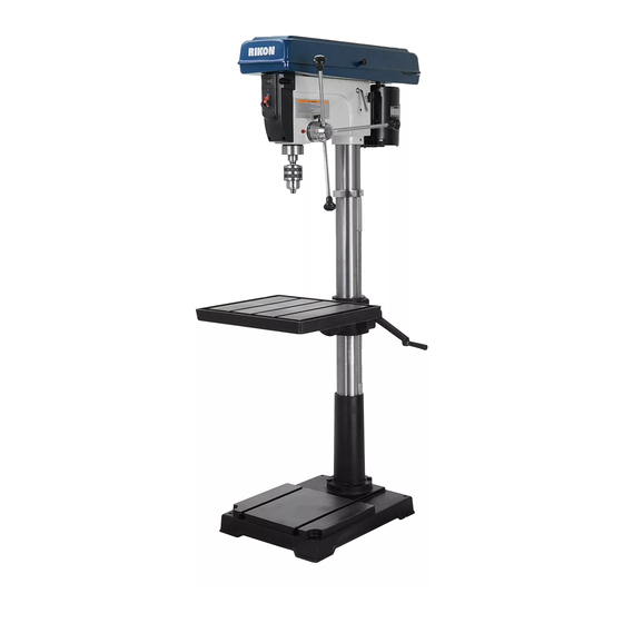
GETTING TO KNOW YOUR MACHINE Belt Cover On/Off Spindle Switch Depth Lock Spindle Return Spring Motor Collar Feed Pulley Chuck Handle Table Tension Tilt Lever Angle Column & Lock Rack Scale Knob Table Table Table Support Support Column Locking Handle Table Tilting Table Locking Bolt... -
Page 9: Assembly
ASSEMBLY Additional Tools Needed for Assembly - #2 Phillips Screwdriver - 18mm (11/16”) or Adjustable Wrench - Mallet or Hammer with Piece of Wood THE MACHINE MUST NOT BE PLUGGED IN AND THE POWER SWITCH MUST BE IN THE OFF POSITION UNTIL ASSEMBLY IS COMPLETE. Figure 1 BASE AND COLUMN ASSEMBLY 1. - Page 10 ASSEMBLY Continued from page 9 8. Install the locking lever handle onto the table support bracket. Tightening the locking lever handle secures the table support to the column so that it does not move during the remaining assembly steps, and in normal drill press operation (Figure 5).
- Page 11 ASSEMBLY INSTALLING & REMOVING THE CHUCK OPEN CHUCK JAWS AND ARBOR IMPORTANT! It is important that the tapered hole in the chuck, tapered hole in the spindle and both tapered ends of the arbor are free of any grease, oil, lacquer or rust protection.
-
Page 12: Adjustments
ASSEMBLY REMOVING THE CHUCK THE MACHINE MUST NOT BE PLUGGED IN AND THE POWER SWITCH MUST BE IN THE OFF POSITION UNTIL ASSEMBLY IS COMPLETE. 1. Open the chuck jaws as wide as possible to prevent damage. 2. Lower the spindle until the slot in the spindle is exposed. -
Page 13: Changing Spindle Speeds
ADJUSTMENTS TILTING THE TABLE 1. Loosen the large nut below the table support arm (A-Fig. 17). This requires a 30mm (1-1/4”) socket or adjustable wrench, not included. 2. The small threaded pin with nut below the 30mm nut (B-Fig. 17) positions the table at 90°. Tighten the nut to withdraw the pin from its index hole in the support frame so that the table can be Figure 17... - Page 14 ADJUSTMENTS Continued from page 13 BELT DEFLECTION FIGURE 21 6. Swing back the tension lever until there is ap- proximately 1/2” deflection in the belt (Fig. 21). 7. Tighten the locking knob on the both sides of drill press head. 8.
-
Page 15: Operation
ADJUSTMENTS SETTING THE RETURN SPRING TENSION THE MACHINE MUST NOT BE PLUGGED IN AND THE POWER SWITCH MUST BE IN THE OFF POSITION UNTIL ALL ADJUSTMENTS ARE COMPLETE. The drill press chuck will automatically return upward to its original starting position when the operating handle is released. -
Page 16: Maintenance
MAINTENANCE Turn the power switch “OFF” and disconnect the plug from the outlet prior to adjusting or maintaining the machine. DO NOT attempt to repair or maintain the electrical components of the motor. Contact a qualified service technician for this type of maintenance. 1. -
Page 17: Troubleshooting
TROUBLESHOOTING TROUBLE PROBABLE CAUSE REMEDY Noisy Operation 1. Incorrect belt tension. 1. Adjust tension. 2. Dry Spindle. 2. Lubricate spindle. 3. Loose spindle pulley. 3. Checking tightness of retaining nut 4. Loose motor pulley. on pulley and tighten if necessary. 4. -
Page 18: Parts Diagrams
PARTS DIAGRAM 30-240 Drill Press Parts Keyed as A & B See Page 21 for the Parts List... - Page 19 PARTS DIAGRAM 30-240 Drill Press Parts Keyed as C See Page 21 for the Parts List NOTE: Please reference the Model Number and Key Number when calling for Replacement Parts. For Parts under Warranty, the Serial Number of your machine is required.
-
Page 20: Parts Diagrams
PARTS DIAGRAM Parts Explosion 30-240 Drill Press Parts Keyed as D... -
Page 21: Parts List
PARTS LIST KEY NO. DESCRIPTION KEY NO. DESCRIPTION Collar-Rack Screw-Hex Head M8x1.25-16 Screw-Hex soc Set M6x1.0-10 Lever-Adjusting Support-Table with Indicator Support-Motor Bracket Crank Mount-Motor Handle crank Lock washer 12mm Rack Nut-Hex M12 Screw-Hex Soc Set M10x1.5-12 Motor Support-Column Nut-Hex M8x1.25 Screw-Hex Head M12x1.75-40 Washer 8... -
Page 22: Accessories
ACCESSORIES All metal construction with slots Approx. Sizes JAWS L x W Jaws Open for mounting on drill press tables. 93-010 3” Vise 3” x 13/16” 3-1/4” Large toggle handles for fast 93-020 4” Vise 4” x 15/16” 4-1/4” adjusting of the jaws. Machined 93-030 5”... -
Page 23: Warranty
WARRANTY... - Page 24 30-240 For more information: 16 Progress Road Billerica, MA 01821 877-884-5167 / 978-528-5380 techsupport@rikontools.com www.rikontools.com 30-240M4...
Need help?
Do you have a question about the 30-240 and is the answer not in the manual?
Questions and answers