Table of Contents
Advertisement
Quick Links
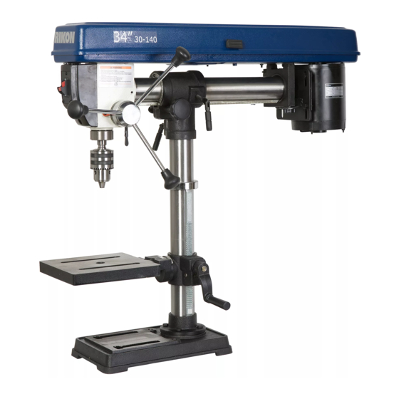
30-140
34" Radial Bench Drill Press
Operator's Manual
Record the serial number and date of purchase in your manual for future reference.
The serial number can be found on the specification label on the rear of your machine.
Serial Number: _________________________
Date of purchase: _________________________
For technical support or parts questions, email techsupport@rikontools.com or call toll free at (877)884-5167
www.rikontools.com
30-140M3
Advertisement
Table of Contents

Related Manuals for Rikon Power Tools 30-140


Summary of Contents for Rikon Power Tools 30-140
- Page 1 30-140 34” Radial Bench Drill Press Operator’s Manual Record the serial number and date of purchase in your manual for future reference. The serial number can be found on the specification label on the rear of your machine. Serial Number: _________________________ Date of purchase: _________________________ For technical support or parts questions, email techsupport@rikontools.com or call toll free at (877)884-5167...
-
Page 2: Table Of Contents
TABLE OF CONTENTS Safety Warnings............................3-6 Electrical Requirements........................5,16 Drill Press Safety Rules ..........................6 Contents of Package........................7 Getting To Know Your Drill Press......................8 I n s t a l l a t i o n ......................... 8 Assembly .............................9-12 Head Assembly..........................9,10 Installing &... -
Page 3: Safety Warnings
SAFETY INSTRUCTIONS IMPORTANT! Safety is the single most important consideration in the operation of this equipment. The following instructions must be followed at all times. Failure to follow all instructions listed below may result in electric shock, fire, and/or serious personal injury. There are certain applications for which this tool was designed. - Page 4 SAFETY INSTRUCTIONS 12. KEEP PROTECTIVE GUARDS IN PLACE AND IN 25. ALWAYS WEAR A DUST MASK TO PREVENT WORKING ORDER. INHALING DANGEROUS DUST OR AIRBORNE PARTICLES, including wood dust, crystalline silica dust 13. AVOID ACCIDENTAL STARTING. Make sure that and asbestos dust. Direct particles away from face and the power switch is in the “OFF”...
-
Page 5: Electrical Requirements
SAFETY INSTRUCTIONS EXTENSION CORDS ELECTRICAL SAFETY THE USE OF AN EXTENSION CORD THIS TOOL MUST BE GROUNDED WITH THIS MACHINE IS NOT RECOMMENDED. For WHILE IN USE TO PROTECT THE OPERATOR FROM best power and safety, plug the machine directly into a ELECTRIC SHOCK. -
Page 6: Drill Press Safety Rules
SAFETY INSTRUCTIONS SPECIFIC SAFETY INSTRUCTIONS FOR DRILL PRESSES This machine is intended for the drilling of wood, composite materials, plastics, ferrous and non-ferrus metals. The permissible workpiece dimensions must be observed (see Technical Specification). Any other use not as specified, including modification of the machine or use of parts not tested and approved by the equipment manufacturer, can cause unforeseen damage and invalidate the warranty. -
Page 7: Contents Of Package
CONTENTS OF PACKAGE Model #30-140 34” Benchtop Radial Drill Press is shipped complete in one box. Unpacking and Clean-up 1. Carefully remove all contents from the shipping carton. Compare the contents with the list of contents to make sure that all of the items are accounted for, before discarding any packing material. Place parts on a protected surface for easy identification and assembly. -
Page 8: Getting To Know Your Drill Press
GETTING TO KNOW YOUR MACHINE For reference, the Parts Diagram and Parts List are on pages 16 and 17. INSTALLATION MOVING & INSTALLING THE DRILL PRESS 2. Align the machine so that during use, any kickback will not face aisles, doorways, or other work areas that bystanders may be in. -
Page 9: Assembly
ASSEMBLY THE MACHINE MUST NOT BE PLUGGED IN AND THE POWER SWITCH MUST BE IN THE OFF POSITION UNTIL ASSEMBLY IS COMPLETE. BASE AND COLUMN ASSEMBLY 1. Place the base (A-Fig. 1) on a level floor where the machine will be used. Figure 1 2. -
Page 10: Installing & Removing The Chuck And Arbor
ASSEMBLY Assistance is needed for this next step. 2. Place the drill press head (A-Fig. 6) onto the column (B-Fig. 6) as far as it will go. 3. Attach the 2 clamping levers (part# 30B) on the drill press column guide (part# 18B). Fig. 7. 4. - Page 11 ASSEMBLY THE MACHINE MUST NOT BE PLUGGED IN AND THE POWER SWITCH MUST BE IN THE OFF POSITION UNTIL ASSEMBLY IS COMPLETE. 3. Carefully insert the chuck and arbor assembly into the spindle, making sure to align the flat part of the arbor with the spindle. Fig. 11. 4.
-
Page 12: Installing The Table
ASSEMBLY INSTALLING THE TABLE 1. Install the arm onto the table support with hex bolt (A-Fig.15) and make sure the scale is on zero position (B-Fig.15). If necessary, adjust the hex socket screw (C-Fig.16) to lever the table 90 degree to the spindle. Figure 16 Figure 15 2. - Page 13 ADJUSTMENTS 5. Move the head back to a vertical position . 6. Pull the guide pin out and rotate until it seats in the guide pin slot. 7. Tighten the lock handle. Adjusting the Drill Press Head Forward and Backwards 1.
-
Page 14: Changing Spindle Speeds
ADJUSTMENTS TILTING THE TABLE 1. Loosen the nut below the table. Fig. 24. 2. Tilt table to desired angle. 3. A Tilt scale and pointer are provided on the bracket to indicate the angle. 4. Tighten nut. Figure 24 CHANGING SPINDLE SPEEDS 1. -
Page 15: Setting The Spindle Lock
ADJUSTMENTS SETTING THE SPINDLE LOCK 1. Loosen the depth stop collar lock (A-Fig.28). 2. Lower the spindle to the desired depth. Fig. 29. 3. Turn the depth stop collar clockwise until the collar stops (B-Fig.28). 4. Tighten the depth stop collar lock. Figure 28 SETTING THE DRILL DEPTH 1. -
Page 16: Wiring Diagram
® RIKON Power Tools Inc. (“Seller”) warrants to only the original retail consumer/purchaser of our products that each product be free from defects in materials and workmanship for a period of five (5) years from the date the product was purchased at retail. -
Page 17: Troubleshooting
TROUBLESHOOTING TROUBLE PROBABLE CAUSE REMEDY Noisy Operation 1. Incorrect belt tension. 1. Adjust tension. 2. Dry Spindle. 2. Lubricate spindle. 3. Loose spindle pulley. 3. Checking tightness of retaining nut on pulley and tighten if necessary. 4. Loose motor pulley. 4. -
Page 18: Parts Diagram
PARTS DIAGRAM... -
Page 19: Parts List
PARTS LIST DESCRIPTION DESCRIPTION PART NO. PART NO. P30-140-19B Belt - “V” P30-140-1A Horizontal - tube Pulley nut P30-140-2A Cover mount P30-140-20B Spindle pulley P30-140-3A Motor mount P30-140-21B Insert pulley P30-140-4A Motor P30-140-22B P30-140-23B Retaining ring P30-140-5A Nut M8 Ball bearing P30-140-6A Flat washer P30-140-24B... - Page 20 30-140 For more information: 16 Progress Road Billerica, MA 01821 877-884-5167 / 978-528-5380 techsupport@rikontools.com LINK TO RIKON WEBSITE www.rikontools.com 30-140M3...
Need help?
Do you have a question about the 30-140 and is the answer not in the manual?
Questions and answers