Table of Contents
Advertisement
Quick Links
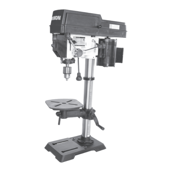
30-212VS
12" VS Drill Press
Operator's Manual
Record the serial number and date of purchase in your manual for future reference.
Serial Number: _________________________
Date of purchase: _________________________
For technical support or parts questions, email techsupport@rikontools.com or call toll free at (877)884-5167
www.rikontools.com
30-212VSM1
Advertisement
Table of Contents
Troubleshooting

Related Manuals for Rikon Power Tools 30-212VS


Summary of Contents for Rikon Power Tools 30-212VS
- Page 1 30-212VS 12” VS Drill Press Operator’s Manual Record the serial number and date of purchase in your manual for future reference. Serial Number: _________________________ Date of purchase: _________________________ For technical support or parts questions, email techsupport@rikontools.com or call toll free at (877)884-5167 www.rikontools.com...
- Page 2 TABLE OF CONTENTS Specifications........................2 Safety Instructions ..................3 - 6, 16 Getting To Know Your Machine ....................7 Contents of Package .....................7 - 8 Installation ........................8 Assembly ........................9 - 11 Adjustments.......................12 - 15 Operation ........................15 - 18 Maintenance ........................19 Electricals & Wiring Diagram ..................5 & 20 Troubleshooting ......................20 - 21 Notes ......................21 &...
-
Page 3: Safety Symbols
SAFETY INSTRUCTIONS IMPORTANT! Safety is the single most important consideration in the operation of this equipment. The following instructions must be followed at all times. Failure to follow all instructions listed below may result in electric shock, fire, and/or serious personal injury. There are certain applications for which this tool was designed. - Page 4 SAFETY INSTRUCTIONS 12. KEEP PROTECTIVE GUARDS IN PLACE AND IN 25. ALWAYS WEAR A DUST MASK TO PREVENT WORKING ORDER. INHALING DANGEROUS DUST OR AIRBORNE PARTICLES, including wood dust, crystalline silica dust 13. AVOID ACCIDENTAL STARTING. Make sure that and asbestos dust. Direct particles away from face and the power switch is in the “OFF”...
-
Page 5: Extension Cords
SAFETY INSTRUCTIONS EXTENSION CORDS ELECTRICAL SAFETY THE USE OF AN EXTENSION CORD THIS 120V TOOL MUST BE GROUND- WITH THIS MACHINE IS NOT RECOMMENDED. For ED WHILE IN USE TO PROTECT THE OPERATOR FROM best power and safety, plug the machine directly into a ELECTRIC SHOCK. - Page 6 SAFETY INSTRUCTIONS SPECIFIC SAFETY INSTRUCTIONS FOR DRILL PRESSES This machine is intended for the drilling of wood, composite materials, plastics, ferrous and non-ferrus metals. The permissible workpiece dimensions must be observed (see Technical Specification). Any other use not as specified, including modification of the machine or use of parts not tested and approved by the equipment manufacturer, can cause unforeseen damage and invalidate the warranty.
-
Page 7: Getting To Know Your Machine
Stand or Bench CONTENTS OF PACKAGE Model #30-212VS 12” Variable Speed Drill Press is shipped complete in one box. Unpacking and Clean-up 1. Carefully remove all contents from the shipping carton. Compare the contents with the list of contents to make sure that all of the items are accounted for, before discarding any packing material. -
Page 8: Contents Of Package
CONTENTS OF PACKAGE LIST OF LOOSE PARTS J. Crank Handle A. Head Assembly K. Table Bracket Lever Handle Tools Needed for Assembly B. Base C. Column Assembly L. Table Arm Lever Handle M. Hex Head Bolts (4) D. Table - Phillips Screwdriver N. -
Page 9: Assembly
ASSEMBLY BASE AND COLUMN ASSEMBLY NOTE: Parts referenced throughout the manual refer to the identification key numbers of the Parts 1. Place the Base (Part #1, Figure 1, A) on a level floor Diagrams and Parts Lists on pages 22 to 25. where the machine will be used. - Page 10 ASSEMBLY THE MACHINE MUST NOT BE PLUGGED IN AND THE POWER SWITCH MUST BE IN THE OFF POSITION UNTIL ASSEMBLY IS COMPLETE. HEAD ASSEMBLY Assistance is needed for this next step. 1. Carefully lift and place the drill press head onto the top of the column.
-
Page 11: Assembly
ASSEMBLY INSTALLING & REMOVING THE CHUCK IMPORTANT! It is important that the tapered hole in the chuck, tapered hole in the spindle and both tapered ends of the arbor are free of any grease, oil, lacquer or rust protection. These tapered surfaces must be absolutely clean for a precision fitting of the parts, so slipping of the chuck during use does not occur unless there is extreme rotational pressure during use. -
Page 12: Adjustments
ADJUSTMENTS ADJUSTING THE TABLE 1. TO RAISE OR LOWER THE TABLE along the column, the Locking Handle (#9) must be loosened. FIG. 13, A. 2. Use the Crank Handle (#19, B) to raise or lower the work table to the height that you need. NOTE: Always raise the table to your final height so that the gears mesh together best to prevent slippage. - Page 13 ADJUSTMENTS ADJUSTING THE DEPTH STOP The Depth Stop is used for boring multiple holes at the same, identical depth. The threaded rod includes a scale and a large quick release nut for fast setting of the depth that the spindle/chuck will travel. FIG. 17. The chuck’s travel distance/depth is read on the scale at the bottom of the upper Depth Setting Nuts (#31).
- Page 14 ADJUSTMENTS ADJUSTING THE QUILL HEIGHT The Quill (#27, Fig. 20, A) can be set to a particular depth or position with the lower, Scale Nut (#31, B) on the Depth Threaded Rod (#32, C). This nut is located under the cast metal Depth Plate (Fig. 20, D). 1.
-
Page 15: Adjustments
ADJUSTMENTS ADJUSTING THE SPINDLE RETURN SPRING The Chuck will automatically return upward to its original starting position when the operating handle is released. The Return Spring Mechanism, FIG. 22, has been preset at the factory and should not require any adjustments. However, should the spring tension decline and need adjustment, follow these steps;... - Page 16 OPERATION LED LIGHT SWITCH The drill press includes a special LED Bulb (#53) that is located under the head casting by the column to best light your work from behind to eliminate shadow interference (FIG. 25, A). The light’s ON/OFF switch is located on the lower front of the drill press head, the switch on the right side.
- Page 17 OPERATION INSTALLING AND REMOVING DRILL BITS The 30-212VSR Drill Press includes a 3-jaw keyed chuck for the holding of drill bits with shanks up to 5/8” diameter (1/32”-5/8” / 0.8 -16mm). To install a drill bit; 1. Disconnect the machine from the power source and make sure that the switch is in the OFF position.
-
Page 18: Operation
OPERATION IMPORTANT! It is strongly recommended that you read books, trade magazines, or get formal training to maximize the potential of using your Drill Press, while also minimizing the risks. Before turning on the machine, review the safety precautions on pages 3 to 6. Make sure that you fully understand the features, adjustments and capabilities of the machine that are outlined throughout this manual. -
Page 19: Maintenance
MAINTENANCE Turn the power switch “OFF” and disconnect the plug from the outlet prior to adjusting or maintaining the machine. DO NOT attempt to repair or maintain the electrical components of the motor. Contact a qualified service technician for this type of maintenance. 1. -
Page 20: Troubleshooting
WIRING DIAGRAM This machine must be grounded. Replacement of the power supply cable should only be done by a qualified electrician. See page 5 for additional electrical information. Green Black Motor 120V White White WIRING White White Black White White Electronic relay White... -
Page 21: Troubleshooting
TROUBLESHOOTING FOR YOUR OWN SAFETY, ALWAYS TURN OFF AND UNPLUG THE MACHINE BEFORE CARRYING OUT ANY TROUBLESHOOTING. PROBLEM PROBABLE CAUSE REMEDY Noisy operation 1. Excessive machine vibration 1. Tighten any loose parts. Secure drill 2. Dry spindle press to the floor or plywood base 3. - Page 22 PARTS DIAGRAM...
- Page 23 ST2.9X6.5 P30-212VS-41 Digital Readout Transformer 120V - 3.5V/2W P30-212VS-42 Phillips Screw+spring washer+flat washer M5x8 P30-212VS-43 Outer Teeth Washer φ5 P30-212VS-44 Hex Nut P30-212VS-45 Quill Set Screw M8 P30-212VS-46 SEE PAGES 24 & 25 FOR A CONTINUATION OF #30-212VS PART NUMBERS...
- Page 24 Handle P30-212VS-86 Shifter Fork Assembly P30-212VS-87 Washer φ15 P30-212VS-88 Motor Tension Lever Handle 45 P30-212VS-89 Hex Screw M8x12 P30-212VS-90 Spring Pin φ5x13 P30-212VS-91 Hex Screw M8x12 P30-212VS-92 Washer φ25 P30-212VS-93 SEE PAGE 21 FOR A CONTINUATION OF #30-212VS PART NUMBERS...
- Page 25 PARTS LIST PART NO. QTY. KEY NO. DESCRIPTION Ring P30-212VS-94 Ball Bearing 61905RZ P30-212VS-95 A4x4x60 P30-212VS-96 Bushing P30-212VS-97 Cam Base P30-212VS-98 Hex Screw M6x16 P30-212VS-99 Cam Shaft P30-212VS-100 Hex Screw M6x8 P30-212VS-101 Cam Bushing P30-212VS-102 A4x4x66 P30-212VS-103 Ball Bearing 6201RZ P30-212VS-104 Washer φ10...
-
Page 26: Notes
NOTES Use this section to record maintenance, service and any calls to Technical Support:... -
Page 27: Accessories
(1/4”, 5/16”, 3/8” 1/2”) and plastic storage case. RIKON Power Tools Inc. (“Seller”) warrants to only the original retail consumer/purchaser of our products that each product be free from defects in materials and workmanship for a period of five (5) years from the date the product was purchased at retail. - Page 28 30-212VS For more information: 16 Progress Road Billerica, MA 01821 877-884-5167 / 978-528-5380 techsupport@rikontools.com www.rikontools.com 30-212VSM1...
Need help?
Do you have a question about the 30-212VS and is the answer not in the manual?
Questions and answers