Table of Contents
Advertisement
Quick Links
Download this manual
See also:
Operator's Manual
Advertisement
Table of Contents

Subscribe to Our Youtube Channel
Related Manuals for Rikon Power Tools 30-100


Summary of Contents for Rikon Power Tools 30-100
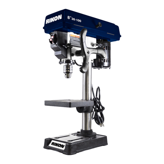
- Page 1 8” Bench Drill Press Model: 30-100 Record the serial number and date of purchase in your manual for future reference. Serial number: Date of purchase: For more information: www.rikontools.com info@rikontools.com For Parts or Questions: techsupport@rikontools.com 877-884-5167 Part # 30-100M2...
-
Page 2: Safety Warnings
Safety Warnings IMPORTANT! Safety is the single most important consideration in the operation of this equipment. The following instructions must be followed at all times. There are certain applications for which this tool was designed. We strongly recommend that this tool not be modified and/ or used for any other application other than that for which it was designed. -
Page 3: Special Safety Rules For Drill Presses
ALWAYS DISCONNECT TOOLS. Disconnect tools before servicing and when changing accessories such as blades, bits, and cutters. ALWAYS AVOID ACCIDENTAL STARTING. Make sure switch is in “OFF” position before plugging in cord. NEVER LEAVE TOOLS RUNNING UNATTENDED. ALWAYS CHECK FOR DAMAGED PARTS. Before initial or continual use of the tool, a guard or other part that is damaged should be checked to assure that it will operate properly and perform its intended function. -
Page 4: Table Of Contents
Assembly................................7-9 Adjustments............................9-10 Troubleshooting.................................11 Notes..................................12 Wiring Diagram............................12 Electrical Requirements...........................13 Explosion Diagrams/Parts Lists......................14-21 Warranty.................................22 Notes..................................23 Specifications Model Number 30-100 Swing 8” Motor 1/3 HP, 120V, 3.6A, 60Hz Motor Speed 1750 RPM Spindle Speeds 620, 1100, 1720, 2340, 3100 RPM Chuck Type Keyed Chuck Capacity 1/2”... -
Page 5: Unpacking And Contents
Feed Handle Bolt (See Contents Below) Feed Handle Owner’s Manual Column 8” Bench Drill Press Model: 30-100 Record the serial number and date of purchase in your manual for future reference. Serial number: Date of purchase: For more information: www.rikontools.com info@rikontools.com... -
Page 6: Getting To Know Your Drill Press
Getting to Know Your Drill Press Item Description Item Description Base Belt Cover Table Lock Handle Motor Table Feed Handle Column Support Tube Chuck Handle Return Spring Chuck Key Holder Depth Stop Switch... -
Page 7: Assembly
Assembly The machine must not be plugged in and the power switch must be in the OFF position until assembly is complete. Tools Required for Assembly Item Description Phillips Screwdriver Adjustable or 13mm Wrench Unpacking and Clean-up 1. Carefully finish removing all contents from shipping carton. Compare contents of the shipping carton with the list shown on page 5. - Page 8 Assembly 3. Slide the drill press head over the column. (Fig.03) Fig.03 4. Center the drill press head over the table and base. Tighten the drill press head into position by locking the two hex screws on the side of the casting.
-
Page 9: Adjustments
Assembly 6. The feed handle (A-Fig.06) is secured to the feed shaft with the supplied Allen bolt (B-Fig.06). Fig.06 Adjustments 7. Depth Stop: The depth stop and scale are found on the left side of the switch box. To adjust, lower the drill chuck until pointer shows desired depth on the scale. - Page 10 Adjustments Assembly 9. Changing Spindle Speed: The 30-100 Bench Drill Press has five spindle speeds. To change, lift the cover with the handle (A-Fig.09). Fig.09 10. Loosen the motor lock knob (A-Fig.10). Move the motor (B-Fig.10) manually toward the feed handle to take tension off of the belt.
-
Page 11: Troubleshooting
Troubleshooting... -
Page 12: Notes
Notes Use this section to record maintenance, service and any calls to Technical Support: Wiring Diagram WARNING:This machine must be grounded. Replacement of the power supply cable should only be done by a qualified electrician. -
Page 13: Electrical Requirements
Electrical Requirements In the event of a malfunction or breakdown, grounding provides a path of least resistance for electric current to reduce the risk of electric shock. This tool is equipped with an electric cord having an equipment-grounding conductor and a grounding plug. The plug must be plugged into a matching outlet that is properly installed and grounded in accordance with all local codes and ordinances. -
Page 14: Explosion Diagrams/Parts Lists
Explosion Diagram... - Page 15 Parts List KEY No. Description 30-100-1A Bushing-Rubber 30-100-2A Knob 30-100-3A Screw-Pan Hd.M5x0.8-1.2 30-100-4A Belt-”V” 5/16x26 30-100-5A Guard w/Labels 30-100-6A Screw-Washer Hd. 30-100-7A Ring Retaining 30-100-8A Bearing-Ball 17mm 30-100-9A Spacer 30-100-10A Insert-Pulley 30-100-11A Pulley-Spindle 30-100-12A Nut-Pulley 30-100-13A Clamp Cord 30-100-14A Screw-Pan Hd.M5x.08-16...
- Page 16 Explosion Diagram...
- Page 17 Parts List KEY No. Description 30-100-1B Head w/Roll Pin & Trim 30-100-2B Nut-Lock M8x1.25-8 30-100-3B Washer 8MM 30-100-4B Screw-Hex M8x1.25-25 30-100-5B Pulley-Motor 30-100-6B Screw-Hex Soc. Set M8x1.25-8 30-100-7B Motor 30-100-8B Stop-Motor 30-100-9B Spring-Motor Stop 30-100-10B Knob-Motor Adjusting 30-100-11B Screw-Hex Soc. Set M8x1.25-8...
- Page 18 Explosion Diagram...
- Page 19 Parts List KEY No. Description 30-100-1C Gasket-Quill 30-100-2C Bearing-Ball 12mm 30-100-3C Tube-Quill 30-100-4C Screw-Pan M5x0.8-20 30-100-5C Collar-Stop 30-100-6C Ring Retaining 30-100-7C Shaft-Spindle 30-100-8C Chuck 30-100-9C Key-Chuck 30-100-10C Nut-Hex M6x1.0 30-100-11C Nut-Hex M5x.08 30-100-12C Rod-Stop...
- Page 20 Explosion Diagram...
- Page 21 Parts List KEY No. Description 30-100-1D Support-Table w/Scale 30-100-2D Support-Lock Handle 30-100-3D Tube/Support 30-100-4D Base 30-100-5D Screw-Hex Hd. M8x1.25-20 30-100-6D Screw-Hex Hd. 1/2-12x7/8 30-100-7D Table...
-
Page 22: Warranty
Warranty 5-Year Limited Warranty RIKON Power Tools Inc. (“Seller”) warrants to only the original retail consumer/purchaser of our products that each product be free from defects in materials and workmanship for a period of five (5) years from the date the product was purchased at retail. This warranty may not be transferred. -
Page 23: Notes
Notes... -
Page 24: For More Information
For more information: 16 Progress Rd Billerica, MA 01821 877-884-5167 / 978-528-5380 techsupport@rikontools.com www.rikontools.com Copyright RIKON Power Tools, Inc. 2011 Printed in China 7/11...
Need help?
Do you have a question about the 30-100 and is the answer not in the manual?
Questions and answers