Table of Contents
Advertisement
Quick Links
Download this manual
See also:
Manual
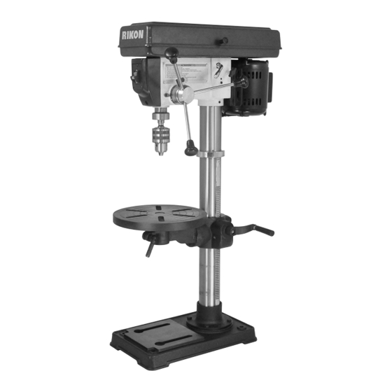
30-120
13" Bench Drill Press
Operator's Manual
Record the serial number and date of purchase in your manual for future reference.
The serial number can be found on the specification label on the rear of your machine.
Serial Number: _________________________
Date of purchase: _________________________
For technical support or parts questions, email techsupport@rikontools.com or call toll free at (877)884-5167
www.rikontools.com
30-120M4
Advertisement
Table of Contents

Related Manuals for Rikon Power Tools 30-120


Summary of Contents for Rikon Power Tools 30-120
- Page 1 30-120 13" Bench Drill Press Operator’s Manual Record the serial number and date of purchase in your manual for future reference. The serial number can be found on the specification label on the rear of your machine. Serial Number: _________________________ Date of purchase: _________________________ For technical support or parts questions, email techsupport@rikontools.com or call toll free at (877)884-5167...
-
Page 2: Table Of Contents
TABLE OF CONTENTS Specifications........................2 Safety Instructions ......................3 - 6 Getting To Know Your Machine ....................7 Contents of Package .....................7 - 8 Installation ........................8 Assembly ........................9 - 12 Adjustments.......................13 - 14 Maintenance ........................15 Electricals & Wiring Diagram ..................5 & 15 Troubleshooting ......................16 Accessories ......................17 Warranty ..........................17... -
Page 3: Safety Instructions
SAFETY INSTRUCTIONS IMPORTANT! Safety is the single most important consideration in the operation of this equipment. The following instructions must be followed at all times. Failure to follow all instructions listed below may result in electric shock, fire, and/or serious personal injury. There are certain applications for which this tool was designed. - Page 4 SAFETY INSTRUCTIONS 12. KEEP PROTECTIVE GUARDS IN PLACE AND IN 25. ALWAYS WEAR A DUST MASK TO PREVENT WORKING ORDER. INHALING DANGEROUS DUST OR AIRBORNE PARTICLES, including wood dust, crystalline silica dust 13. AVOID ACCIDENTAL STARTING. Make sure that and asbestos dust. Direct particles away from face and the power switch is in the “OFF”...
-
Page 5: Electricals & Wiring Diagram
SAFETY INSTRUCTIONS EXTENSION CORDS ELECTRICAL SAFETY THE USE OF AN EXTENSION CORD THIS TOOL MUST BE GROUNDED WITH THIS MACHINE IS NOT RECOMMENDED. For WHILE IN USE TO PROTECT THE OPERATOR FROM best power and safety, plug the machine directly into a ELECTRIC SHOCK. - Page 6 SAFETY INSTRUCTIONS SPECIFIC SAFETY INSTRUCTIONS FOR DRILL PRESSES This machine is intended for the drilling of wood, composite materials, plastics, ferrous and non-ferrus metals. The permissible workpiece dimensions must be observed (see Technical Specification). Any other use not as specified, including modification of the machine or use of parts not tested and approved by the equipment manufacturer, can cause unforeseen damage and invalidate the warranty.
-
Page 7: Getting To Know Your Machine
U Table Angle Scale & Lock Nut CONTENTS OF PACKAGE Model #30-120 13” Benchtop Drill Press is shipped complete in one box. Unpacking and Clean-up 1. Carefully remove all contents from the shipping carton. Compare the contents with the list of contents to make sure that all of the items are accounted for, before discarding any packing material. -
Page 8: Installation
CONTENTS OF PACKAGE LIST OF LOOSE PARTS A Drill Press Head Assembly B Column & Table Support Arm C Worm Elevation Gear D Table Raising Handle E Column Table Support Lever Handle F Table Clamp Lever Handle G Chuck Key H 5/8”... -
Page 9: Assembly
ASSEMBLY THE MACHINE MUST NOT BE PLUGGED IN AND THE POWER SWITCH MUST BE IN THE OFF POSITION UNTIL ASSEMBLY IS COMPLETE. BASE AND COLUMN ASSEMBLY 1. Place the base (A-Fig. 1) on a level floor where the machine will be used. 2. - Page 10 ASSEMBLY HEAD ASSEMBLY - CONTINUED THE MACHINE MUST NOT BE PLUGGED IN AND THE POWER SWITCH MUST BE IN THE OFF POSITION UNTIL ASSEMBLY IS COMPLETE. 2. Align the drill press head (A-Fig. 6) with the base of the drill press (B-Fig. 6). Figure 6 3.
- Page 11 ASSEMBLY INSTALLING & REMOVING THE CHUCK OPEN CHUCK JAWS AND ARBOR IMPORTANT! It is important that the tapered hole in the chuck, tapered hole in the spindle and both tapered ends of the arbor are free of any grease, oil, lacquer or rust protection.
- Page 12 ASSEMBLY REMOVING THE CHUCK 1. Open the chuck jaws as wide as possible to prevent damage. 2. Lower the spindle until the slot in the spindle is exposed. (Fig. 14) 3. Position the table approximately 1/2” below the extended chuck. Figure 14 4.
-
Page 13: Adjustments
ADJUSTMENTS TABLE ADJUSTMENTS RAISING AND LOWERING THE TABLE 1. Loosen the column lock (A-Fig. 19) on the table support bracket (B-Fig. 19). 2. Turn the crank to raise or lower the table to the desired height. 3. Tighten the column lock (A-Fig. 19). Figure 19 NOTE: The table can rotate 360 by loosening... - Page 14 ADJUSTMENTS CHANGING SPINDLE SPEEDS - continued 5. Place the belt on the pulleys in relation to the speed chosen on the speed selection chart starting with the motor pulley first. (Fig. 23) 6. Push the belt tension handle (B-Fig. 24) back Figure 23 ward on the motor until there is approximately 1/2"...
-
Page 15: Maintenance
MAINTENANCE Turn the power switch “OFF” and disconnect the plug from the outlet prior to adjusting or maintaining the machine. DO NOT attempt to repair or maintain the electrical components of the motor. Contact a qualified service technician for this type of maintenance. 1. -
Page 16: Troubleshooting
TROUBLESHOOTING TROUBLE PROBABLE CAUSE REMEDY Noisy Operation 1. Incorrect belt tension. 1. Adjust tension. 2. Dry Spindle. 2. Lubricate spindle. 3. Loose spindle pulley. 3. Checking tightness of retaining nut on pulley and tighten if necessary. 4. Loose motor pulley. 4. -
Page 17: Accessories
® RIKON Power Tools Inc. (“Seller”) warrants to only the original retail consumer/purchaser of our products that each product be free from defects in materials and workmanship for a period of five (5) years from the date the product was purchased at retail. -
Page 18: Parts Diagram
PARTS DIAGRAM Parts Explosion 30-120 13” Drill Press NOTE: Please reference the Manufacturer’s Part Number when calling for Replacement Parts. For Parts under Warranty, the Serial Number of your machine is required. -
Page 19: Parts List
PARTS LIST DESCRIPTION PART NO. DESCRIPTION PART NO. Screw-Hex Soc Set M6 P30-120-1A Pivot-Idler P30-120-14C Pulley-Center Collar-Rack P30-120-2A P30-120-15C Bearing-Ball 15mm Gear-Helical P30-120-3A P30-120-16C Crank P30-120-4A Knob-Motor Adjusting P30-120-1D Screw-Socket Set M10 Table P30-120-6A P30-120-2D Clamp-Table P30-120-7A Handle-Belt Tension P30-120-3D Screw-Hex Head M16x20-35 P30-120-8A Pin-Stop... - Page 20 30-120 For more information: 16 Progress Road Billerica, MA 01821 877-884-5167 / 978-528-5380 techsupport@rikontools.com www.rikontools.com 30-120M4...
Need help?
Do you have a question about the 30-120 and is the answer not in the manual?
Questions and answers