Table of Contents
Advertisement
Quick Links
Download this manual
See also:
Owner's Manual
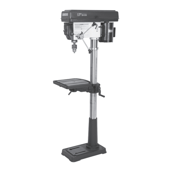
30-230
17" Floor Drill Press
Operator's Manual
Record the serial number and date of purchase in your manual for future reference.
Serial Number: _________________________
Date of purchase: _________________________
For technical support or parts questions, email techsupport@rikontools.com or call toll free at (877)884-5167
www.rikontools.com
30-230M4
Advertisement
Table of Contents

Related Manuals for Rikon Power Tools 30-230


Summary of Contents for Rikon Power Tools 30-230
- Page 1 30-230 17” Floor Drill Press Operator’s Manual Record the serial number and date of purchase in your manual for future reference. Serial Number: _________________________ Date of purchase: _________________________ For technical support or parts questions, email techsupport@rikontools.com or call toll free at (877)884-5167 www.rikontools.com...
-
Page 2: Table Of Contents
TABLE OF CONTENTS Specifications........................2 Safety Instructions ......................3 - 6 Getting To Know Your Machine ....................7 Contents of Package .....................7 - 8 Installation ........................8 Assembly ........................9 - 12 Adjustments.......................12 - 15 Operation ........................15 Maintenance ........................16 Electricals & Wiring Diagram ..................5 & 16 Parts Diagrams &... -
Page 3: Safety Instructions
SAFETY INSTRUCTIONS IMPORTANT! Safety is the single most important consideration in the operation of this equipment. The following instructions must be followed at all times. Failure to follow all instructions listed below may result in electric shock, fire, and/or serious personal injury. There are certain applications for which this tool was designed. - Page 4 SAFETY INSTRUCTIONS 12. KEEP PROTECTIVE GUARDS IN PLACE AND IN 25. ALWAYS WEAR A DUST MASK TO PREVENT WORKING ORDER. INHALING DANGEROUS DUST OR AIRBORNE PARTICLES, including wood dust, crystalline silica dust 13. AVOID ACCIDENTAL STARTING. Make sure that and asbestos dust. Direct particles away from face and the power switch is in the “OFF”...
-
Page 5: Electricals & Wiring Diagram
SAFETY INSTRUCTIONS SAFETY INSTRUCTIONS EXTENSION CORDS ELECTRICAL SAFETY THE USE OF AN EXTENSION CORD THIS 120V TOOL MUST BE GROUND- WITH THIS MACHINE IS NOT RECOMMENDED. For ED WHILE IN USE TO PROTECT THE OPERATOR FROM best power and safety, plug the machine directly into a ELECTRIC SHOCK. -
Page 6: Safety Instructions
SAFETY INSTRUCTIONS SPECIFIC SAFETY INSTRUCTIONS FOR DRILL PRESSES This machine is intended for the drilling of wood, composite materials, plastics, ferrous and non-ferrus metals. The permissible workpiece dimensions must be observed (see Technical Specification). Any other use not as specified, including modification of the machine or use of parts not tested and approved by the equipment manufacturer, can cause unforeseen damage and invalidate the warranty. -
Page 7: Getting To Know Your Machine
Support Base CONTENTS OF PACKAGE Model #30-230 17” Drill Press is shipped complete in one box. Unpacking and Clean-up 1. Carefully remove all contents from the shipping carton. Compare the contents with the list of contents to make sure that all of the items are accounted for, before discarding any packing material. Place parts on a protected surface for easy identification and assembly. -
Page 8: Installation
CONTENTS OF PACKAGE LIST OF LOOSE PARTS Tools Needed for Assembly F Parts Bags include: - Phillips Screwdriver A Drill Press Head Assembly Chuck, Chuck Arbor, Chuck Key, - 10mm, 16mm, 24mm or B Table Drift Key, Handles (3), Lid Knob, Adjustable Wrench C Base Bolts (4), Feed Handles (3) -
Page 9: Assembly
ASSEMBLY THE MACHINE MUST NOT BE PLUGGED IN AND THE POWER SWITCH MUST BE IN THE OFF POSITION UNTIL ASSEMBLY IS COMPLETE. BASE AND COLUMN ASSEMBLY 1. Place the base (A-Fig. 1) on a level floor where the machine will be used. Figure 1 2. - Page 10 ASSEMBLY THE MACHINE MUST NOT THE MACHINE MUST NOT BE PLUGGED IN AND THE POWER SWITCH BE PLUGGED IN AND THE POWER SWITCH MUST BE IN THE OFF POSITION UNTIL MUST BE IN THE OFF POSITION UNTIL ASSEMBLY IS COMPLETE. ASSEMBLY IS COMPLETE.
-
Page 11: Installing The Chuck
ASSEMBLY INSTALLING THE CHUCK 1. Carefully insert the arbor’s short, JT3 tapered end into the rear tapered hole of the chuck. (Figure 8). 2. Next, take the chuck and insert the long, MT2 tapered end of the arbor into the drill press spindle’s tapered hole. -
Page 12: Adjustments
ASSEMBLY THE MACHINE MUST NOT BE PLUGGED IN AND THE POWER SWITCH MUST BE IN THE OFF POSITION UNTIL ASSEMBLY IS COMPLETE. INSTALLING THE TABLE 1. Install the large Locking Lever (#16A) onto the rear joint of the table support bracket and tighten Figure 12 the locking lever. - Page 13 ADJUSTMENTS 4. Choose the desired speed by referring to the speed selection chart that is attached to the lid interior. 5. Position the belts on the pulleys in relation to the speed chosen on the speed selection chart starting with the motor pulley first. (Figure 16). Figure 16 6.
- Page 14 ADJUSTMENTS THE MACHINE MUST NOT BE PLUGGED IN AND THE POWER SWITCH MUST BE IN THE OFF POSITION UNTIL ALL ADJUSTMENTS ARE COMPLETE. RAISING AND LOWERING THE TABLE 1. Loosen the column lock handle (Figure 19, A) on the table support bracket (B). 2.
-
Page 15: Operation
ADJUSTMENTS SETTING THE RETURN SPRING TENSION THE MACHINE MUST NOT BE PLUGGED IN AND THE POWER SWITCH MUST BE IN THE OFF POSITION UNTIL ALL ADJUSTMENTS ARE COMPLETE. The drill press chuck will automatically return upward to its original starting position when the operating handle is released. -
Page 16: Maintenance
MAINTENANCE Turn the power switch “OFF” and disconnect the plug from the outlet prior to adjusting or maintaining the machine. DO NOT attempt to repair or maintain the electrical components of the motor. Contact a qualified service technician for this type of maintenance. 1. -
Page 17: Parts Diagrams & Parts Lists
PARTS DIAGRAM & PARTS LIST COLUMN & TABLE SHEET A NOTE: Please reference the Part Number when calling for Replacement Parts. For Parts under Warranty, the Serial Number of your machine is required. DESCRIPTION PART NO. KEY NO. QTY. Hex. socket set screw M6X10 P1-M6X10GB80B Collar-Rack P1-1701011... -
Page 18: Parts Diagrams & Parts Lists
PARTS DIAGRAM & PARTS LIST SPINDLE ASSEMBLY SHEET B NOTE: Please reference the Part Number when calling for Replacement Parts. For Parts under Warranty, the Serial Number of your machine is required. DESCRIPTION PART NO. QTY. KEY NO. Nut-Lock P1-1503005 Ring-Locking P1-1503004 Washer... - Page 19 PARTS DIAGRAM & PARTS LIST PULLEY & DRIVE ASSEMBLY SHEET C NOTE: Please reference the Part Number when calling for Replacement Parts. For Parts under Warranty, the Serial Number of your machine is required. DESCRIPTION PART NO. QTY. KEY NO. Ring-Retaining P1-1702024 Bearing Ball 25mm...
- Page 20 PARTS DIAGRAM...
- Page 21 PARTS LIST DESCRIPTION PART NO. QTY. KEY NO. Knob-Motor Adjusting P1-1502005 Screw-Socket Set M10X1.5-12 P1-M10X12GB80B Handle-Belt Tension P1-1702004 Pin-Stop P1-1504010 Ring-Depth Stop with Scale P1-1504003-00001Z Lock-Depth Screw P1-1504012 P1-1504001-02+1-1504002 Guide Scale P1-1504004 Feed Handles P1-1504005-01 Knob P1-1504011-01001S Lock washer-EXT M5 P1-WSH5GB862D2B Screw-Pan HD M5X8 P1-M5X8GB818B...
-
Page 22: Troubleshooting
TROUBLESHOOTING FOR SAFETY, ALWAYS TURN OFF AND UNPLUG THE MACHINE BEFORE CARRYING OUT ANY TROUBLESHOOTING. TROUBLE PROBABLE CAUSE REMEDY Noisy Operation 1. Incorrect belt tension. 1. Adjust tension. 2. Dry Spindle. 2. Lubricate spindle. 3. Loose spindle pulley. 3. Checking tightness of retaining nut on pulley and tighten if necessary. -
Page 23: Accessories
ACCESSORIES & WARRANTY Approximate Sizes JAWS L x W Jaws Open 93-010 3” Vise 3” x 13/16” 3-1/4” 93-020 4” Vise 4” x 15/16” 4-1/4” 93-030 5” Vise 5” x 7/8” 5” 93-040 6” Vise 6” x 1” 6” All metal construction with side slots for mounting on drill press tables. - Page 24 30-230 For more information: 16 Progress Road Billerica, MA 01821 877-884-5167 / 978-528-5380 techsupport@rikontools.com www.rikontools.com 30-230M4...
Need help?
Do you have a question about the 30-230 and is the answer not in the manual?
Questions and answers