Table of Contents
Advertisement
Quick Links
Advertisement
Table of Contents

Related Manuals for Rikon Power Tools 10-201


Summary of Contents for Rikon Power Tools 10-201
-
Page 2: General Safety Warnings
Safety Warning IMPORTANT! Safety is the single most important consideration in the operation of this equipment. The following instructions must be followed at all times. There are certain applications for which this tool was designed. We strongly recommend that this tool not be modified and/ or used for any other application other than that for which it was designed. - Page 3 ALWAYS DISCONNECT TOOLS. Disconnect tools before servicing and when changing accessories such as blades, bits, and cutters. ALWAYS AVOID ACCIDENTAL STARTING. Make sure switch is in “OFF” position before plugging in cord. NEVER LEAVE TOOLS RUNNING UNATTENDED. ALWAYS CHECK FOR DAMAGED PARTS. Before initial or continual use of the tool, a guard or other part that is damaged should be checked to assure that it will operate properly and perform its intended function.
-
Page 5: Unpacking And Contents
Unpacking and Checking Contents Unpack your 10-201 Contractor Saw from its carton and check to see that you have all of the following items. Do not turn your saw ON if any of these items are missing. You may cause injury to yourself or damage to your machine. -
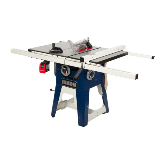
Page 6: Getting To Know Your Table Saw
Getting to Know Your Table Saw A) Miter Gauge B) Blade Guard Assembly with riving knife C) Motor Cover D) Bevel Scale E) Height Adjustment Handwheel F) Bevel Adjustment Handwheel G) Fence Hooks(2) H) On/Off Switch I) Mobile Base Caster Assembly J) Fence... - Page 7 1. Attach leg assemblies (A) to the right (J) and left (k) of the table saw cabinet by placing (B) eight M8X16mm carriage screws through the mounting • The table saw is a heavy machine; two people may be holes and place an M8 flat washer, M8 lock washer required for certain assembly operations.
- Page 8 Fig.3 2. Thread the locking knob (D) onto the threaded end of the shaft. SEE FIG. 5 3. Repeat the steps above to assemble the remaining handwheel and locking knob onto the bevel shaft located on the side of the cabinet. WRENCH AND HOOK ASSEMBLY Fig.6 HANDWHEEL ASSEMBLY...
- Page 9 Fig.7 EXTENSION WING ASSEMBLY CAUTION: The extension wing is heavy; two people are required for assemble. 1.One person put right/left extension wing on the top of cabinet. Alignment pin into bottom of wing (A). SEE FIG.10 2. Install the belt on the Arbor Pulley and raise motor by loosing 1 of the motor mounting screws (B) to Fig.10 reach the belt distance for assembling the belt on...
- Page 10 3. The user can adjust the flatness for the extension 3. The user can adjust the flatness for the extension 8. Make sure both wings are aligned, if not, refer to step Wings to obtain more flatness. We suggest that user Wings to obtain more flatness.
- Page 11 FENCE ASSEMBLY 4. Connecting the right guide tube (long) and left guide tube (short) with cap (D), and place them on the front rail. 5. The guide tube must be fasten by eight M6X16mm hex socket round head screws (C) with M6 flat washer and M6 lock washer.
-
Page 12: Assembly
RIVING KNIFE/SPLITTER COMPONENTS Fig.22 ASSEMBLY Note: Remove the table insert (A) (Table insert is gripped by four magnets on the table). SEE FIG. 21 Fig.21 Fig.23 INSTALLING THE RIVING KNIFE/SPLITTER 1. Loosen the knob (C), line up the riving knife/splitter in the proper direction to the mounting bracket (B). - Page 13 CONVERSION THE SPLITTER TO RIVING 1. Remove the hex nut (K) and outer flange (J) from the blade arbor (I). Note: The arbor has a right hand KNIFE thread; to loosen the hex nut turn it counterclockwise. 2. Place a 10 saw blade (Z) onto the blade arbor (I), "...
- Page 14 CONNECTING SWITCH CORD TO MOTOR CORD 3. Pull slack in switch cord into the cabinet. Make sure that the power cord inside of the cabinet Is properly routed and clear of the saw blade and any pinch points for all blade height and blade angle settings.
- Page 15 RAISING AND LOWERING THE BLADE ADJUSTING BLADE BEVEL POSITIVE STOPS Fig. 31 Fig. 32 1. To adjust blade to a 90-degree blade bevel positive The blade height adjustment handwheel and handwheel stop, raise the saw blade (A) to its highest position. lock knob are located on the front of the cabinet above the SEE FIG .
- Page 16 Fig. 34 1. Raise the saw blade to its highest point. 2. Place a combination square (A) on the saw table with one edge (B) of the square against the left miter slot (C). SEE FIG. 35 3. Adjust the square so the rule (D) just touches the saw blade.
- Page 17 1. To align the blade parallel to the miter slot, first BEVEL ARROW ADJUSTMENT loosen two hex socket head screws (A) under the front 1. Make certain that the blade is at 90-degrees to the side of the table saw. This is the same side as the table surface with a combination square.
- Page 18 TABLE INSERT ADJUSTMENT 1. The miter gauge has adjustable positive stops at 0- degree and 45-degrees or it can be manually set at any angle between 60-degrees. 2. To rotate miter gauge body (A), loosen knob (B) and pull out plunger (C) and rotate miter gauge body to SEE FIG.
- Page 19 To turn the table saw off, press the large red “OFF” paddle (B) or lift the paddle and press directly on the A separate electrical circuit should be used for your Red " OFF" button. table saw. The circuit should not be less than #14 4.
- Page 20 Push the reset thermal-overload button on the side of the 6. Is the guard assembly installed and functional? ON/OFF switch assembly. Make certain that the saw 7. Have you checked the saw blade clearance when it blade and work are has been cleared of debris before is adjusted to varying angles and depths? restarting saw.
- Page 21 Cross-cut Blade: Used for cutting across the grain. Dado Blade: There are two types of dado blades: 10 cross-cut blades have between 60-80 teeth and stack and wobble. Stack dadoes involve more setup a shallow gullet. SEE FIG 45. time, but they provide a superior finish cut when compared to a wobble dado.
-
Page 22: Operations
RIPPING Do not stand directly behind the workpiece when ripping. SEE FIG.49 Ripping means to cut with the grain of the wood. In Fig.49 other materials such as MDF or plywood, ripping simply means to cut lengthwise. To rip a board: 1.Inspect the board for soundness.You will need a straight edge to rip with accuracy. - Page 23 1. Remove the table insert, splitter guard, and regular saw blade. 2. Attach and adjust the dado blade system as recommended in the dado blade's instructions.’ 3. Install the dado table insert.(Not included) 4. Raise the blade system up to the desired depth of the dado.
- Page 24 LUBRICATION PROTECTION CAST IRON TABLE FROM The table saw has sealed lubricated bearings in the RUST motor housing that do not require any additional lubrication from the operator. Use a wire brush to clean off the worm gears and trunnions and apply a white lithium grease to keep them lubricated.
-
Page 25: Electrical Requirements
ELECTRICAL REQUIREMENTS... - Page 26 In the event of a malfunction or breakdown, GROUND- provides the path of least resistance for electric The smaller the gauge-number, the larger the diameter current and reduces the risk of electric shock. The plug of the extension cord is. If in doubt of the proper size of MUST be plugged into a matching electrical receptacle an extension cord, use a shorter and thicker cord.
-
Page 27: Parts Explosion & List
PARTS LIST... - Page 28 PART PART DESCRIPTION DESCRIPTION RIGHT ANTI KICKBACK FIGURE 91011618 91011629 RIGHT BLADE GUARD TWIST SPRING 91011619 91011630 SHOULDERED SCR 16000019 3X30mm SPRING PIN 91011620 ROUND PIN 91011631 LEFT ANTI KICKBACK FIGURE 12000445 M4X10mm ROUND HD CUTTING SCR 91011632 ANTI KICKBACK FINGER SUPPORT 12000533 M4X6mm HEX SOC SET SCR W/FLAT POINT...
- Page 29 MITER GAUGE POWER SWITCH TABLE TOP & WINGS...
- Page 30 PART PART DESCRIPTION DESCRIPTION 91011664 SWITCH PADDLE LEFT EXTENSION WING 10” 91011025 12000004C M4X25mm ROUND HD TAP SCR 1/4-28 X 3/8" NYLON SET SCR 12000008C 91011428 SWITCH TABLE INSERT LEFT PAD 91011033 91011710 91011170 SWITCH BOX TABLE INSERT RIGHT PAD 91011702 TABLE INSERT 33000001...
- Page 32 PART PART DESCRIPTION DESCRIPTION NUT L.H. JAM 5/8-18 91011214 KNOB END CAP 11000006 M6 HEX NUT 91011211 HANDWHEEL LOCK KNOB 11000011 12000171 SPECIAL HEX SOC HD SCR M5X12mm PAN HD SCR 91011287C 247A 91060060 SPRING (6203 LLB) BALL BEARING 18000001 247B 91060059 HANDLE...
- Page 33 PART PART DESCRIPTION DESCRIPTION 91011730 91011250AC 301A 91011370 91011251 301B 91011731 12000138C M6X12mm PAN HD SCR 12000345C 19000001C 13000003C 91011252 14000002C 91011240 91011706 91011239 12000127C M6X10MM HEX SOC HD SCR 91011121 306A 13000002C 35000385 SCALE, LEFT 20" CAPACITY 306B 14000001C 91011733 327A 91011732...
- Page 35 PART PART DESCRIPTION DESCRIPTION 12000152 M5X10mm SCREW 12000176 M8X55 BOLT 91011736 MOTOR COVER 91011703 LEVELING SCREW 402A 33000979 LABEL 33000977 NAME PLATE 402B 33000980 LABEL 91011740 PLATE 91011562 SCREW 33000951 BEVEL SCALE 91011680 91011136 INSULATOR 404A 91011709 431A 12000014 M4*15 PAN HD SCR 91011737 CABINET ASSY 431B...
- Page 36 Extension Wing Screw Package Front/ Back Rail Screw Package A) M8 FLAT WASHER 91011024C A) 5/16-18*5/8 HEX SOC HD SCR 12000483 B) M8 LOCK WASHER 14000002C B) M8 FLAT WASHER 13000003C C) 5/16-18X55mm HEX SOC SET SCR 12000529 C) M8 LOCK WASHER 14000002C D) 5/16-18*5/8 HEX HD SCR 12000345C...
-
Page 37: Warranty
Warranty 5-Year Limited Warranty RIKON Power Tools Inc. (“Seller”) warrants to only the original retail consumer/purchaser of our products that each product be free from defects in materials and workmanship for a period of fi ve (5) years from the date the product was purchased at retail. This warranty may not be transferred. -
Page 38: For More Information
For more information: 16 Progress Rd Billerica, MA 01821 877-884-5167 / 978-528-5380 techsupport@rikontools.com www.rikontools.com , s l 2013... - Page 39 TSB 18 11.10 A T T E N T I O N The following procedure is to help you fine tune your table top, wings and miter slot. When assembled correctly, your table top will be within .008-.010 and the miter slot will be ¾”...
- Page 40 A T T E N T I O N The following information is an add-on page designed to provide extra details in assembling the 10-201 Contractor Table Saws. Please see the location images as an reference during assembling. Extension Wing Screw Package...
Need help?
Do you have a question about the 10-201 and is the answer not in the manual?
Questions and answers