Table of Contents
Advertisement
Quick Links
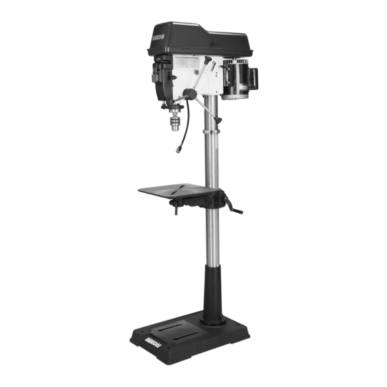
30-217
17" VS Drill Press
Operator's Manual
Record the serial number and date of purchase in your manual for future reference.
The serial number can be found on the specification label on the rear of your machine.
Serial Number: _________________________
Date of purchase: _________________________
For technical support or parts questions, email techsupport@rikontools.com or call toll free at (877)884-5167
www.rikontools.com
30-217M2
Advertisement
Table of Contents

Related Manuals for Rikon Power Tools 30-217


Summary of Contents for Rikon Power Tools 30-217
- Page 1 30-217 17” VS Drill Press Operator’s Manual Record the serial number and date of purchase in your manual for future reference. The serial number can be found on the specification label on the rear of your machine. Serial Number: _________________________ Date of purchase: _________________________ For technical support or parts questions, email techsupport@rikontools.com or call toll free at (877)884-5167...
-
Page 2: Table Of Contents
TABLE OF CONTENTS Specifications........................2 Safety Instructions ......................3 - 6 Getting To Know Your Machine ....................7 Contents of Package .....................7 - 8 Installation ........................8 Assembly ........................9 - 11 Adjustments.......................12 - 15 Operation ........................15 - 16 Maintenance ........................17 Electricals & Wiring Diagram ..................5 & 18 Troubleshooting ......................18 - 19 Notes ...........................19 Parts Diagrams &... -
Page 3: Safety Instructions
SAFETY INSTRUCTIONS IMPORTANT! Safety is the single most important consideration in the operation of this equipment. The following instructions must be followed at all times. Failure to follow all instructions listed below may result in electric shock, fire, and/or serious personal injury. There are certain applications for which this tool was designed. - Page 4 SAFETY INSTRUCTIONS 12. KEEP PROTECTIVE GUARDS IN PLACE AND IN 25. ALWAYS WEAR A DUST MASK TO PREVENT WORKING ORDER. INHALING DANGEROUS DUST OR AIRBORNE PARTICLES, including wood dust, crystalline silica dust 13. AVOID ACCIDENTAL STARTING. Make sure that and asbestos dust. Direct particles away from face and the power switch is in the “OFF”...
-
Page 5: Electricals & Wiring Diagram
SAFETY INSTRUCTIONS ELECTRICAL SAFETY EXTENSION CORDS THIS TOOL IS PRE-WIRED FOR 115V THE USE OF AN EXTENSION CORD WITH THIS MACHINE IS NOT RECOMMENDED. For CIRCUITS, AND MUST BE GROUNDED WHILE IN USE TO PROTECT THE OPERATOR FROM ELECTRIC SHOCK. best power and safety, plug the machine directly into a dedicated, grounded electrical outlet that is within the IN THE EVENT OF A MALFUNCTION OR BREAKDOWN,... - Page 6 SAFETY INSTRUCTIONS SPECIFIC SAFETY INSTRUCTIONS FOR DRILL PRESSES This machine is intended for the drilling of wood, composite materials, plastics, ferrous and non-ferrus metals. The permissible workpiece dimensions must be observed (see Technical Specification). Any other use not as specified, including modification of the machine or use of parts not tested and approved by the equipment manufacturer, can cause unforeseen damage and invalidate the warranty.
-
Page 7: Getting To Know Your Machine
Base Support CONTENTS OF PACKAGE Model #30-217 17” Variable Speed Drill Press is shipped complete in one box. Unpacking and Clean-up 1. Carefully remove all contents from the shipping carton. Compare the contents with the list of contents to make sure that all of the items are accounted for, before discarding any packing material. Place parts on a protected surface for easy identification and assembly. -
Page 8: Installation
CONTENTS OF PACKAGE LIST OF LOOSE PARTS J. Crank Handle A. Head Assembly K. Large Lever Handle Tools Needed for Assembly B. Base C. Column Assembly L. Small Lever Handle M. Drive Handles (3) D. Table - Phillips Screwdriver N. Special Wrench - 24mm E. -
Page 9: Assembly
4. Insert the table post (C) into the table support bracket (B) as shown in Figure 4. Tighten the locking lever (A) to secure the table in position. FIG. 3 LINK TO THE #30-217 ASSEMBLY VIDEO INSTRUCTIONS ON THE RIKON WEBSITE WWW.RIKONTOOLS.COM... - Page 10 ASSEMBLY THE MACHINE MUST NOT BE PLUGGED IN AND THE POWER SWITCH MUST BE IN THE OFF POSITION UNTIL ASSEMBLY IS COMPLETE. HEAD ASSEMBLY Assistance is needed for this next step. 1. Carefully lift and place the drill press head onto the top of the column.
- Page 11 ASSEMBLY INSTALLING & REMOVING THE CHUCK IMPORTANT! It is important that the tapered hole in the chuck, tapered hole in the spindle and both tapered ends of the arbor are free of any grease, oil, lacquer or rust protection. These tapered surfaces must be absolutely clean for a precision fitting of the parts, so slipping of the chuck during use does not occur unless there is extreme rotational pressure during use.
-
Page 12: Adjustments
ADJUSTMENTS ADJUSTING THE TABLE 1. TO RAISE OR LOWER THE TABLE along the column, the Locking Handle (#12, on Parts Diagram A) must be loosened. FIG. 13, A. 2. Use the Crank Handle (#6A, B) to raise or lower the work table to the height that you need. NOTE: Always raise the table to your final height so that the gears mesh together best to prevent slippage. - Page 13 ADJUSTMENTS ADJUSTING THE DEPTH STOP The Depth Stop is used for boring multiple holes at the same, identical depth. The threaded rod includes a scale and a large quick release nut for fast setting of the depth that the spindle/chuck will travel. FIG. 17. The chuck’s travel distance/depth is read on the scale at the top of the Depth Setting Nut (#16 on Parts Diagram D).
- Page 14 ADJUSTMENTS ADJUSTING THE QUILL HEIGHT The Quill (#6D, Fig. 20, A) can be set to a particular depth or position with the lower, round Depth Motion Nut (#14D, B) on the Depth Threaded Rod (#15D, C). This nut is located under the metal Depth Plate (#58D, FIG.
-
Page 15: Operation
CHANGING MOTOR VOLTAGE The 30-217 VS Drill Press is equipped with a dual voltage 115/230V motor. To change from the factory preset 115V operating mode to a 230V circuit, consult the wiring diagram on page 18. - Page 16 OPERATION INSTALLING AND REMOVING DRILL BITS The 30-217 VS Drill Press includes a 3-jaw keyed chuck (ref. page 11) for the holding of drill bits with shanks up to 5/8” diameter. To install a drill bit; 1. Disconnect the machine from the power source and make sure that the switch is in the OFF position.
-
Page 17: Maintenance
MAINTENANCE Turn the power switch “OFF” and disconnect the plug from the outlet prior to adjusting or maintaining the machine. DO NOT attempt to repair or maintain the electrical components of the motor. Contact a qualified service technician for this type of maintenance. 1. -
Page 18: Troubleshooting
For 115V wiring; Connect the blue & brown motor terminal wires to the black switch wire lead, and connect the black & white terminal wires to the white switch wire lead. * NOTE: The 30-217 is pre-wired for 115V use. -
Page 19: Notes
TROUBLESHOOTING FOR YOUR OWN SAFETY, ALWAYS TURN OFF AND UNPLUG THE MACHINE BEFORE CARRYING OUT ANY TROUBLESHOOTING. PROBLEM PROBABLE CAUSE REMEDY Noisy operation 1. Excessive machine vibration 1. Tighten any loose parts. Secure drill 2. Dry spindle press to the floor or plywood base 3. -
Page 20: Parts Diagrams & Parts Lists
PARTS DIAGRAM COLUMN & TABLE SHEET A NOTE: Please reference the Manufacturer’s Part Number when calling for Replacement Parts. For Parts under Warranty, the Serial Number of your machine is required. - Page 21 PARTS LIST COLUMN & TABLE SHEET A DESCRIPTION PART NO. QTY. KEY NO. Base P30-217-1A Hex bolt M12x40 P30-217-2A Support column P30-217-3A Rack P30-217-4A Handle assembly P30-217-5A Crank P30-217-6A Support table, with indicator P30-217-7A Gear - helical P30-217-8A Worm - elevation P30-217-9A Collar rack P30-217-10A...
- Page 22 PARTS DIAGRAM...
- Page 23 PARTS LIST...
- Page 24 PARTS DIAGRAM...
- Page 25 PARTS LIST PULLEY & DRIVE ASSEMBLY SHEET C DESCRIPTION PART NO. QTY. KEY NO. Poly-V-Belt P30-217-1C Lid handle P30-217-2C Cross recess pan head screw M5X12 P30-217-3C Protecting bushing P30-217-4C Guard P30-217-5C Screw P30-217-6C Rubber bushing P30-217-7C Hex socket cap screw M10X20 P30-217-8C Washer P30-217-9C...
- Page 26 PARTS DIAGRAM & PARTS LIST SPINDLE ASSEMBLY SHEET D PART QTY. DESCRIPTION Chuck 5/8” JT3 P30-217-1D Arbor P30-217-2D Spindle P30-217-3D Bearing P30-217-4D Key - drift P30-217-5D Tube - quill P30-217-6D Spacer - bearing P30-217-7D Bearing P30-217-8D Washer P30-217-9D Lock nut P30-217-10D Hex cap screw M6X30 P30-217-11D...
-
Page 27: Accessories
® RIKON Power Tools Inc. (“Seller”) warrants to only the original retail consumer/purchaser of our products that each product be free from defects in materials and workmanship for a period of five (5) years from the date the product was purchased at retail. - Page 28 30-217 For more information: 16 Progress Road Billerica, MA 01821 877-884-5167 / 978-528-5380 techsupport@rikontools.com LINK TO RIKON WEBSITE www.rikontools.com 30-217M2...
Need help?
Do you have a question about the 30-217 and is the answer not in the manual?
Questions and answers