Table of Contents
Advertisement
Quick Links
Advertisement
Table of Contents

Subscribe to Our Youtube Channel
Related Manuals for Toshiba GX9


Summary of Contents for Toshiba GX9
- Page 1 March, 2014 GX9 ASD & O NSTALLATION PERATION ANUAL...
- Page 3 GX9 ASD Installation & Operation Manual Document Number: 66893-001 March, 2014...
- Page 5 - all without any user intervention! The GX9 ASD is a very powerful tool, yet surprisingly simple to operate. The user-friendly Electronic Operator Interface (EOI) of the GX9 ASD has an easy-to-read LCD screen and a high-intensity LED display.
- Page 6 The sales contract contains the entire obligation of Toshiba International Corporation. The warranty contained in the contract between the parties is the sole warranty of Toshiba International Corporation and any statements contained herein do not create new warranties or modify the existing warranty.
- Page 7 This manual was written by the Toshiba International Corporation Technical Publications Group. This group is tasked with providing technical documentation for the GX9 Adjustable Speed Drive. Every effort has been made to provide accurate and concise information to you, our customer.
- Page 8 TOSHIBA INTERNATIONAL CORPORATION GX9 Adjustable Speed Drive Please complete the Warranty Card supplied with the GX9 ASD and return it to Toshiba International Corporation by prepaid mail. This will activate the 12-month warranty from the date of installation; but, shall not exceed 18 months from the shipping date.
-
Page 9: Table Of Contents
Power Factor Correction ....................12 Light Load Conditions ......................12 Motor/Load Combinations ....................12 Load-Produced Negative Torque ..................13 Motor Braking ........................13 GX9 ASD Characteristics .....................14 Over-Current Protection ....................14 GX9 ASD Capacity ......................14 Using Vector Control ......................14 Local/Remote Operation ....................14 GX9 ASD Installation and Operation Manual... - Page 10 Operation (Local) ......................60 Default Setting Changes ....................61 Startup Wizard Requirements .....................62 Running the Startup Wizard .....................62 Command Mode and Frequency Mode Control ..............66 Command Control (F003) ....................66 Frequency Control (F004) ....................67 Command and Frequency Control Selections..............68 GX9 ASD Installation and Operation Manual...
- Page 11 User Notification Codes ....................224 Alarms ..........................225 Trips/Faults ........................228 Viewing Trip Information ....................233 Clearing a Trip ......................233 Part Numbering Convention and Ordering Information ..........234 Cable/Terminal Specifications ....................236 Voltage/Current Specifications ...................237 Enclosure Dimensions/Weight ....................238 GX9 ASD Optional Devices ....................245 GX9 ASD Installation and Operation Manual...
- Page 12 GX9 ASD Installation and Operation Manual...
-
Page 13: General Safety Information
The word CAUTION without the safety alert symbol indicates CAUTION a potentially hazardous situation exists that, if not avoided or if instructions are not followed precisely, may result in equipment and property damage. GX9 ASD Installation and Operation Manual... -
Page 14: Special Symbols
DO NOT remove or cover any of these labels. If the labels are damaged or if additional labels are required, contact the Toshiba Customer Support Center. Labels attached to the equipment are there to provide useful information or to indicate an imminently hazardous situation that may result in serious injury, severe property and equipment damage, or loss of life if safe procedures or methods are not followed as outlined in this manual. -
Page 15: Equipment Inspection
• The storage temperature range of the GX9 ASD is -13° to 149° F (-25° to 65° C). • DO NOT store the unit in places that are exposed to outside weather conditions (i.e., wind, rain, snow, etc.). -
Page 16: Installation Precautions
Installation and Connections on pg. 15 for further information on ventilation requirements. • The ambient operating temperature range of the GX9 ASD is 14° to 104° F (-10° to 40° C). Mounting Requirements • Only Qualified Personnel shall install this equipment. -
Page 17: Conductor Routing And Grounding Precautions
Ensure that the 3-phase input power is NOT connected to the output of the ASD. This will damage the ASD and may cause injury to personnel. • Ensure the correct phase sequence and the desired direction of motor rotation in the Bypass mode (if applicable). GX9 ASD Installation and Operation Manual... -
Page 18: Protection
ASD unit. Note: Dynamic braking is not available on the 100 HP – 400 HP GX9 ASDs. If EMI/RFI noise is of concern, the DBR wiring shall be three-core screened cable. The screen shall connect to the ASD enclosure and the resistor enclosure. -
Page 19: Residual Voltage Warning
Ensure that the 3-phase power to the system is off and that the system is locked out and tagged out before performing maintenance or repair on the GX9 ASD system. The relationship of MCCB1 to the total system is shown in Figure Figure 1. Placement of the MCCB1 circuit breaker in the GX9 ASD system. DANGER Always energized. -
Page 20: System Integration Precautions
A detailed system analysis and job safety analysis shall be performed by the systems designer and/ or systems integrator before the installation of the ASD component. Contact the Toshiba Customer Support Center for options availability and for application-specific system integration information if required. -
Page 21: System Setup Requirements
When using an ASD output disconnect, the ASD and the motor must be stopped before the disconnect is either opened or closed. Closing the output disconnect while the 3-phase output of the ASD is active may result in equipment damage or injury to personnel. GX9 ASD Installation and Operation Manual... -
Page 22: Operational And Maintenance Precautions
Charge Indicator LED has turned off once the ASD power has been turned off before coming into contact with any circuits. • DO NOT attempt to disassemble, modify, or repair the ASD. Contact the Toshiba Customer Support Center for repair information. •... -
Page 23: Motor Characteristics
The default setting for the overload detection circuit is set to the maximum rated current of the GX9 ASD at the factory. This setting will have to be adjusted to match the rating of the motor with which the GX9 ASD is to be used. -
Page 24: Operation Above 60 Hz
DO NOT connect a power factor correction capacitor or surge absorber to the three-phase output of the GX9 ASD. If the GX9 ASD is used with a motor that is equipped with a capacitor for power factor correction, remove the capacitor from the motor. -
Page 25: Load-Produced Negative Torque
Load-Produced Negative Torque When the GX9 ASD is used with a load that produces negative torque (an overhauling load), the over- voltage or over-current protective functions of the GX9 ASD may cause nuisance tripping. To minimize the undesirable effects of negative torque the dynamic braking system may be used if so equipped. -
Page 26: Gx9 Asd Characteristics
Do not apply a level of input voltage to a GX9 ASD that is beyond that which the GX9 ASD is rated. The input voltage may be stepped down when required with the use of a step-down transformer or some other type of voltage reduction system. -
Page 27: Installation And Connections
Installation and Connections The GX9 ASD may be set up initially by performing a few simple configuration settings. To operate properly, the ASD must be securely mounted and connected to a power source (3-phase AC input at the L1/R, L2/S, and L3/T terminals). The control terminals of the ASD may be used by connecting the... -
Page 28: Mounting The Asd
Install the unit securely to the floor or a wall in a well ventilated area that is out of direct sunlight. The ambient temperature rating for the GX9 ASD is from 14° to 104° F (-10° to 40° C). The process of converting AC to DC, and then back to AC produces heat. During normal ASD operation, up to 5% of the input energy to the ASD may be dissipated as heat. -
Page 29: Connecting The Asd
Note: The GX9610K is shown in figure 3 below. See the drawings of the system received for the actual location of the Charge LED. Figure 3. Typical GX9 ASD Charge Indicator LED. Charge LED GX9 ASD Installation and Operation Manual... - Page 30 In the event that the motor rotates in the wrong direction when powered up, reverse any two of the three ASD output power leads (U, V, or W) connected to the motor. Figure 4. The GX9 ASD/Motor Typical Connection Diagram. GX9 ASD Installation and Operation Manual...
-
Page 31: System Grounding
5 kHz 300 ft. 100 ft. Note: Contact Toshiba for application assistance when using lead lengths in excess of those listed. Exceeding the peak voltage rating or the allowable thermal rise time of the motor insulation will reduce the life expectancy of the motor. -
Page 32: I/O And Control
I/O and Control The GX9 ASD can be controlled by several input types and combinations thereof, as well as operate within a wide range of output frequency and voltage levels. This section discusses the ASD control methods and supported I/O functions. -
Page 33: Terminal Descriptions
Emergency Off condition until reset. The S4 terminal is activated by connecting CC to this terminal (Sink mode). This input terminal may be programmed to any of the functions listed in Table 8 on pg. 217 (see F118). GX9 ASD Installation and Operation Manual... - Page 34 ASD goes up so does the FP output pulse rate. This terminal may be programmed to provide an output pulse rate that is proportional to the magnitude of the user-selected item from Table 9 on pg. 221. For further information on this terminal, see parameter F676. GX9 ASD Installation and Operation Manual...
- Page 35 The FLA, FLB, and FLC contacts are rated at 2A/120 VAC and 2A/30 VDC. Figure 5. FLA, FLB, and FLC Switching Contacts Shown in the Normal Operating Condition. Note: The relay is shown in the normal operating condition. During a faulted condition, the relay connection is FLC-to-FLA. GX9 ASD Installation and Operation Manual...
- Page 36 Figure 6. GX9 ASD Terminal Board. CN7A 0–1 mA 0–1 mA 4–20 mA 4–20 mA SW1 and SW2 may be switched to change the full- scale range of the FM and AM output terminals. See F005 F670 more information on the FM and AM terminal adjustments.
-
Page 37: Gx9 Asd Control
GX9 ASD Control The Control Board (P/N 56000) serves as the primary control source for the GX9 ASD and receives input from the Terminal Board (see Figure 6 on pg 24), an Option Card, RS232/RS485 Communications, or the EOI. The Control Board has been enhanced to support two additional functions: Multiple Protocol Communications and the ability to communicate in either half- or full-duplex modes. -
Page 38: Cnu1 And Cnu2 Pinout
Figure 8. Control Board of the GX9 ASD. Sink/Source Switching Option Board TTL I/O (CNU2) Interface (CN3). RS232/RS485 signal I/O (CN3) EOI Connect- RS232/RS485 signal (CNU1) CNU4 25-pin D-type connector. ASD-NANOCOM Connects to the Terminal JP1 Jumpers - Half-/Full-Duplex Selection Board (CN7). -
Page 39: Cn7 Pinout
26). CN7 connects to CN7A of the Terminal Board. Table 3. CN7 pinout assignments. Default settings listed for the programmable terminals. Pin Number Pin Number Pinout Pinout OUT1 OUT2 — — Note: * Open collector output. GX9 ASD Installation and Operation Manual... -
Page 40: I/O Circuit Configurations
Figure 11. RX Input. Figure 12. VI/II Input. Figure 13. P24 Output. Figure 14. PP Output. Figure 15. OUT1/OUT2 Output. Figure 16. FP Output. Figure 17. AM/FM Output. Figure 18. Fault Relay (during fault). GX9 ASD Installation and Operation Manual... -
Page 41: Startup And Test
Table 4. ASD Parameter Changes by Installer/Maintenance Personnel. ASD ID__________Name:______________________Date:_______ Default or Notes Parameter Unit of Parameter Name Previous New Setting Number Measure Setting Note: Settings may also be recorded via Program Utilities Type Reset Save User Settings. GX9 ASD Installation and Operation Manual... -
Page 42: Typical Connection Diagram
Typical Connection Diagram Figure 19. GX9 ASD Typical Connection Diagram. Note: When connecting multiple wires to the PA, PB, PC, or PO terminals, do not connect a solid wire and a stranded wire to the same terminal. Note: The VI, RX, and RR analog input terminals are referenced to CC. -
Page 43: Electronic Operator Interface
The software used with the GX9 ASD is menu driven; thus, making it a select and click environment. The operating parameters of a motor may be selected and viewed or changed using the EOI (or via communications). - Page 44 ASD-EOI-N4-G9 is best suited for this application. Each kit contains all of the hardware required to mount the EOI of the GX9 ASD remotely. System operation and EOI operation while using the remotely-mounted EOI are the same as with the ASD-mounted configuration.
-
Page 45: Eoi Features
— Displays the running frequency, active Fault, or active Alarm information. Rotary Encoder — Used to access the GX9 ASD menu selections, change the value of a displayed parameter (while in edit mode), and performs the Enter key function. Turn the Rotary Encoder either clockwise or counterclockwise to perform the Up or Down functions of the displayed menu selection. -
Page 46: Led/Lcd Screens
Initiates an Emergency Off Fault if pressed twice quickly. The Emergency Off function terminates the GX9 ASD output and stops the motor in accordance with the setting of F603. Resets active Faults and/or active Alarms if pressed twice quickly. The source of the Faults or Alarms must be determined and corrected before normal ASD operation can resume. -
Page 47: Using The Lcd Screen
ASD Output Voltage Figure 23. Program Menu Screen (see pg. 44 for more on the Program Menu Screen). Item Number 1 of 13 Program Menu items Screen Name (Only 5 Items Listed) Primary Menu Items GX9 ASD Installation and Operation Manual... -
Page 48: Eoi Remote Mounting
EOI not be attached to the ASD housing. Remote mounting will also allow for multiple EOI mountings at one location if controlling and monitoring several ASDs from a central location is required. The door-mounted EOI of the GX9 ASD uses the remote mounting kit 58333 to allow for the standard door-mount EOI configuration. -
Page 49: Eoi Installation Precautions
Attach and secure the EOI to the front side of the mounting location using the four 6-32 x 5/16” pan head screws, the #6 split lock washers, and the #6 flat washers. Connect the extension cable. EOI Mounting Dimensions Figure 24. EOI Mounting Dimensions. GX9 ASD Installation and Operation Manual... -
Page 50: Eoi Remote Mounting Using The Asd-Mtg-Kit9
Attach and secure the EOI to the front side of the Bezel Plate using the four 6-32 x 5/16” pan head screws, #6 split lock washers, and the #6 flat washers. Connect the extension cable. EOI ASD-MTG-KIT9 Mounting Dimensions Figure 25. EOI Bezel Plate Mounting Dimensions. GX9 ASD Installation and Operation Manual... -
Page 51: System Configuration And Menu Options
System Configuration and Menu Options Root Menus The Mode key accesses the three primary modes of the GX9 ASD: the Frequency Command mode, the Monitor mode, and the Program mode. From either mode, press the Mode key to loop through to the... - Page 52 (of a multiple motor configuration). The settings of profiles 1 – 4 may be setup at F441, F444, F446, and F448, respectively. VLP Technology Control — This feature enables or disables the Virtual Linear Pump function. GX9 ASD Installation and Operation Manual...
-
Page 53: Monitor Mode
Output Current — Displays the Output Current as a percentage of the rated capacity of the GX9 ASD. DC Bus Voltage — Displays the Bus Voltage as a percentage of the rated capacity of the GX9 ASD. Output Voltage — Displays the Output Voltage as a percentage of the rated capacity of the GX9 ASD. - Page 54 Peak Current — Displays the peak current since the last start was initiated. The current is displayed as a percentage of the rated capacity of the GX9 ASD. Peak Voltage — Displays the peak voltage since the last start was initiated. The voltage is displayed as a percentage of the rated capacity of the GX9 ASD.
-
Page 55: Main Monitor Selections
The selected items, along with their real-time values, are displayed on the Frequency Command screen while the GX9 ASD is running. Not all Monitor Mode items are available for display on the Frequency Command screen. The available items are underlined on pg. -
Page 56: Program Mode Menu Navigation
Output Terminal 2 (OUT2) Function F131 Low Suction/No-Flow Cut Off Mode F934 Low Suction/No-Flow Cut Off Delay Timer F936 Low Suction/No-Flow Cut Input Terminal 5 (S1) Function F115 Low Suction/No-Flow Cut Off Disposition F935 GX9 ASD Installation and Operation Manual... - Page 57 Setup for 60 Hz Save User Restore Factory Defaults Settings Clear Trips Type Reset F007 Clear Run Timer Initialize Typeform Save User Settings Restore User Settings Reload EOI to Factory Defaults Display Parameters Current/Voltage Units Setup F701 GX9 ASD Installation and Operation Manual...
- Page 58 Fault Alarm Point Setting Error Alarm Earth Fault Alarm PID Low Output Disable Alarm Virtual Linear Pump On Virtual Linear Pump Low Frequency Virtual Linear Pump No Flow Contrast Use Rotary Encoder to Adjust GX9 ASD Installation and Operation Manual...
- Page 59 MON 1 Terminal Meter Adjustment F673 MON 2 Terminal Meter Selection F674 MON 2 Terminal Meter Adjustment F675 Low Speed Signal Output Frequency F100 Reach Settings Speed Reach Frequency F101 Speed Reach Detection Band F102 GX9 ASD Installation and Operation Manual...
- Page 60 Analog Input Filter F209 REQUENCY VI/II Point 1 Frequency F202 VI/II Reference Point 1 F201 VI/II Point 2 Frequency F204 Speed Reference Setpoints VI/II Reference Point 2 F203 VI/II Bias F470 VI/II Gain F471 GX9 ASD Installation and Operation Manual...
- Page 61 Pattern Run Group 1 Selection 5 F535 Pattern Run Group 1 Selection 6 F536 Pattern Run Group 1 Selection 7 F537 Pattern Run Group 1 Selection 8 F538 Pattern Run Group 2 Repeat Factor (255 = F540 Continuous) GX9 ASD Installation and Operation Manual...
- Page 62 Preset Speed 4 F021 Preset Speed 5 F022 Preset Speeds Preset Speed 6 F023 Preset Speed 7 F024 Preset Speed 8 F287 Preset Speed 9 F288 Preset Speed 10 F289 Preset Speed 11 F290 GX9 ASD Installation and Operation Manual...
- Page 63 Scan Rate F312 Retry/Restart Lock-on Rate F313 Search Method F314 Search Inertia F315 Regenerative Ridethrough F302 Under-Voltage Trip Enable/Disable F627 Under-Voltage/ Under-Voltage Detection Time F628 Ridethrough Regenerative Ridethrough Control Level F629 Ridethrough Time F310 GX9 ASD Installation and Operation Manual...
- Page 64 Set Points RR Input Point 2 Torque F215 RR Reference Point 2 F212 RX Input Point 1 Torque F220 RX Reference Point 1 F216 RX Input Point 2 Torque F221 RX Reference Point 2 F218 GX9 ASD Installation and Operation Manual...
- Page 65 PID Feedback Input Signal F360 EEDBACK PID Feedback Delay Filter F361 PID Feedback Proportional (P) Gain F362 Feedback Settings PID Feedback Integral (I) Gain F363 PID Deviation Upper Limit F364 PID Deviation Lower Limit F365 GX9 ASD Installation and Operation Manual...
- Page 66 Communication Settings Time Out Action TTL Send Wait Time F805 RS232/RS485 Wire Count F821 RS232/RS485 Send Wait Time F825 TTL ASD-to-ASD Communication F806 RS232/RS485 ASD-to-ASD Communication F826 Address EOI Port Address (Reset ASD after change) GX9 ASD Installation and Operation Manual...
- Page 67 Optional Parameters 5 F894 Autotune Enable/Disable and Reset Config. F400 OTOR Autotune of Motor Constant 3 F414 Vector Motor Model Slip Frequency Gain F401 Motor Capacity (kW) F412 Motor Constant 1 (primary resistance) F402 GX9 ASD Installation and Operation Manual...
- Page 68 PWM Carrier Frequency Setting F300 Carrier Frequency Minimum Carrier Frequency 2.2 kHz F738 Acceleration Time 1 F009 Deceleration Time 1 F010 Accel/Decel 1 – 4 Settings S-Curve Acceleration/Deceleration Pattern 1 F502 Acceleration Time 2 F500 GX9 ASD Installation and Operation Manual...
- Page 69 Reverse Direction Frequency for Automatic High-speed F341 Operation at Light Load V/f Five-Point 1 Frequency F190 V/f Five-Point 1 Voltage F191 V/f Five-Point Setting V/f Five-Point 2 Frequency F192 V/f Five-Point 2 Voltage F193 GX9 ASD Installation and Operation Manual...
- Page 70 Current Differential Gain F454 Exciting Strengthening Coefficient F480 Control Margin Modulation for Current F482 Vector Control Control Margin Modulation for Voltage F483 Vector Control Control Margin Modulation for Constant F484 Vector Control Rocking Start F739 GX9 ASD Installation and Operation Manual...
- Page 71 Program Menu Navigation Parameter Primary Menu Sub Menu Parameter Name Number Enter Password Password and Lockouts Change Password assword and ockouts Lockouts GX9 ASD Installation and Operation Manual...
-
Page 72: System Operation
The Startup Wizard launches upon the first power up of the system and assists with the initial configuration of the input power settings and the output parameters of the GX9 ASD. The GX9 ASD may also be setup via communications, by directly accessing the individual parameters via the menu hierarchy, or using the Direct Access parameter numbers (see 75). -
Page 73: Default Setting Changes
Pressing ESC while the system is performing a Changed From Default search terminates the search. Pressing ESC when done searching (or halted at a changed parameter) returns the system to the Program Menu. Figure 27. Changed From Default screen. GX9 ASD Installation and Operation Manual... -
Page 74: Startup Wizard Requirements
Startup Wizard Requirements The Startup Wizard assists the user with the initial configuration of the GX9 ASD by querying the user for information on the ASD control settings, motor ratings, and ASD display units. The GX9 ASD may also be setup by accessing each of the settings via the Program menu or by using the Direct Access Number of each parameter (see the section titled Direct Access Parameter Information on pg. - Page 75 This parameter allows the user to input the full-load amperage (FLA) of the motor. This value is used by the GX9 ASD to determine the Motor Overload Protection setting for the motor and may be found on the nameplate of the motor.
- Page 76 This parameter allows the user to input the full-load capability of the motor in kilo Watts. This value is used by the GX9 ASD to determine the motor overload protection setting for the motor and may be found on the nameplate of the motor.
- Page 77 11. Wizard Finished! This screen is the final screen of the Startup Wizard. The basic parameters of the GX9 ASD have been set. Click Exit to load the Startup Wizard input and to return to the Frequency Command screen. Additional application-specific programming may be required.
-
Page 78: Command Mode And Frequency Mode Control
Possible Command signal source selections include the following: • Terminal Board (default), • CN8 Option, • Common Serial (TTL), • RS232/RS485, • Communication Card, or • F003 setting (is used if no signal sources are in the Override mode). GX9 ASD Installation and Operation Manual... -
Page 79: Frequency Control (F004)
The Terminal Board is placed in the Override mode by assigning a discrete input terminal to Terminal Frequency Priority and connecting the terminal to CC. Upon activation, VI/II is used as the Terminal Board Override control item. GX9 ASD Installation and Operation Manual... -
Page 80: Command And Frequency Control Selections
Frequency control Override operation. The GX9 ASD reads the command registers of the listed control items of the table from the left to the right. In the table the number 1 indicates that a valid input signal is being received for that control input source;... -
Page 81: Command Control Selections
EOI Port Address to RS232/RS485 to use this feature. Communication Card Routes the control and monitoring I/O to CNU3 of the Control Board of the GX9 ASD (Communication Card connector). Frequency Control Selections The following is a listing and description of the Frequency Mode (F004) selections (Program ... - Page 82 RS232/RS485 to use this feature. Communication Card Routes the control and monitoring I/O to CNU3 of the Control Board of the GX9 ASD (Option Card connector). UP/DOWN Frequency Discrete input terminals may be configured to increase or decrease the speed of the motor by momentarily connecting the assigned discrete input terminal to CC.
-
Page 83: Virtual Linear Pump Setup
Virtual Linear Pump Setup Toshiba International Corporation’s Virtual Linear Pump algorithm allows for direct and precise control of pressure, flow rate, or level. This is achieved without the concerns, instabilities, or complexities that are traditionally associated with pumping system control. This section provides useful setup and operational information for the Virtual Linear Pump system. - Page 84 • The output frequency is greater than the setting of F505, or • The output frequency no longer changes with continued Virtual Linear Pump number changes. The Minimum threshold setting (F917) plus the F919 setting comprises the range of the Minimum threshold zone. GX9 ASD Installation and Operation Manual...
- Page 85 (if using feedback go to Step 22. on pg. 74). Press ESC 20. While in the Local mode, press Run. 21. While running, adjust parame- ters F500 F501 to stabilize operation if unstable. GX9 ASD Installation and Operation Manual...
- Page 86 Process Hold if using feedback (if not using feedback go to Step 19. on pg. 73). 23. While in the Local mode, press Run. Press ESC 24. During operation, adjust parameters F500 F501 stabilize operation if unstable. GX9 ASD Installation and Operation Manual...
-
Page 87: Direct Access Parameter Information
Direct Access Parameter Information The GX9 ASD has the ability to allow the user direct access to the motor control functions. There are two ways in which the motor control parameters may be accessed from the EOI: Program Applicable Menu Path or Program ... - Page 88 3 — RX 4 — RX2 5 — CN8 Option 6 — Binary/BCD (option) 7 — Common Serial (TTL) 8 — RS232/RS485 9 — Communication Option Board 10 — UP/DOWN Frequency 11 — Pulse Input (Option) GX9 ASD Installation and Operation Manual...
- Page 89 With the ASD running at a known value (e.g., output frequency), adjust this parameter until the assigned function produces the desired DC level output at the FM output terminal. F670 for more information on this setting. GX9 ASD Installation and Operation Manual...
- Page 90 Under most operating conditions, as the output frequency of the ASD goes up so does the output voltage (linear acceleration). The ASD has the ability to modify the relationship between frequency and voltage automatically to produce smoother operation or increased (starting) torque (see F502). GX9 ASD Installation and Operation Manual...
- Page 91 ASD reaches its maximum setting. The Base Frequency Voltage 1 Minimum — 25.0 parameter is set at F306. Maximum — 299.0 For proper motor operation, the Base Frequency should be set for the nameplated frequency of the motor. Units — Hz GX9 ASD Installation and Operation Manual...
- Page 92 Units — % smoother operation. Note: Setting an excessive Torque Boost level may cause nuisance tripping and mechanical stress to loads. GX9 ASD Installation and Operation Manual...
- Page 93 4 — V/f Motor OL Trip and No Soft Stall 5 — V/f Motor OL Trip with Soft Stall 6 — V/f Motor with NO OL Trip and No Soft Stall 7 — V/f Motor Soft Stall Only GX9 ASD Installation and Operation Manual...
- Page 94 Preset Speed 2. The binary number is applied to S1 – S4 of the Minimum — Lower Limit (F013) Terminal Board to output the Preset Speed (see F018 for more information on this parameter). Maximum — Upper Limit (F012) Units — Hz GX9 ASD Installation and Operation Manual...
- Page 95 Minimum — 0.0 duration that the ASD output speed is equal to or less than this setting. Maximum — Upper Limit (F012) Units — Hz GX9 ASD Installation and Operation Manual...
- Page 96 Parameter Type — Numerical Factory Default — 2.5 This parameter sets the bandwidth of the Speed Reach Frequency (F101) Changeable During Run — Yes setting. Minimum — 0.0 Maximum — Upper Limit (F012) Units — Hz GX9 ASD Installation and Operation Manual...
- Page 97 F or R. Opening the F and R contact will disable the ASD and the motor will coast to a stop. The control terminal ST may be configured for another function or unused. GX9 ASD Installation and Operation Manual...
- Page 98 Terminal Board will receive priority over commands from the EOI. F260 for more information on using the Jog function. F250 – F252 for more information on DC Injection Braking. Settings: 0 — Disabled 1 — Enabled GX9 ASD Installation and Operation Manual...
- Page 99 S1-S4 on the Terminal Board as binary bits 0 – 3 (F115 – F118). The Frequency Mode 1 (F004) parameter must be set to Binary/BCD. For proper scaling of the binary or BCD input, parameters F228 – F231 must be configured. GX9 ASD Installation and Operation Manual...
- Page 100 Set an unused discrete input terminal to UP/DOWN Frequency (down). Set an unused discrete input terminal to UP/DOWN Frequency (clear). F108 — Select the outcome of the Frequency Mode 1 setting when the ASD is powered down, stopped, or tripped. GX9 ASD Installation and Operation Manual...
- Page 101 In addition, this input terminal must be specified as Normally Open or Normally Closed. This parameter sets the programmable RES terminal to one of the user- selectable functions listed in Table 8 on pg. 217. GX9 ASD Installation and Operation Manual...
- Page 102 The Expansion IO Card Option 1 option board (P/N ETB003Z) is required to use this terminal. See the Expansion IO Card Option 1 instruction manual (D/N 58685) for more information on the function of this terminal. GX9 ASD Installation and Operation Manual...
- Page 103 The Expansion IO Card Option 1 option board (P/N ETB003Z) is required to use this terminal. See the Expansion IO Card Option 1 instruction manual (D/N 58685) for more information on the function of this terminal. GX9 ASD Installation and Operation Manual...
- Page 104 The Expansion IO Card Option 2 option board (P/N ETB004Z) is required to use this terminal. See the Expansion IO Card Option 2 instruction manual (D/N 58686) for more information on the function of this terminal. GX9 ASD Installation and Operation Manual...
- Page 105 This parameter is used to set the functionality of the FL output terminals to one Changeable During Run — No of the user-selectable functions listed in Table 10 on pg. 222. In addition, the output terminals must be specified as Normally Open or Normally Closed. GX9 ASD Installation and Operation Manual...
- Page 106 The Expansion IO Card Option 1 option board (P/N ETB003Z) is required to use this terminal. See the Expansion IO Card Option 1 instruction manual (D/N 58685) for more information on the function of this terminal. GX9 ASD Installation and Operation Manual...
- Page 107 (see waveforms at F140). Minimum — 2 The delay may be increased to provide additional electrical noise immunity or Maximum — 200 to prevent the ASD from responding to contact bounce or chatter. Units — mS GX9 ASD Installation and Operation Manual...
- Page 108 For example, if the OUT1 function is programmed as Overtorque Alarm, Maximum — 200 OUT1 will close 2.0 mS (the default value for OUT1 On Delay) after the overtorque condition occurs. Units — mS The delay may be increased to prevent relay chatter. GX9 ASD Installation and Operation Manual...
- Page 109 This parameter delays the closing of the OUT7 output terminals by the Changeable During Run — No programmed value (see waveforms at F150). Minimum — 2 The delay may be increased to prevent relay chatter. Maximum — 200 Units — mS GX9 ASD Installation and Operation Manual...
- Page 110 This parameter delays the opening of the OUT5 output terminals by the Changeable During Run — No programmed value (see waveforms at F160). Minimum — 2 The delay may be increased to prevent relay chatter. Maximum — 200 Units — mS GX9 ASD Installation and Operation Manual...
- Page 111 This parameter is used only when the parameters for Motor Set 2 are configured and selected. Motor Set 2 may be selected by a properly configured input terminal (see Table 8 on pg. 217). GX9 ASD Installation and Operation Manual...
- Page 112 This parameter is used only when the parameters for Motor Set 3 are configured and selected. Motor Set 3 may be selected by a properly configured input terminal (see Table 8 on pg. 217). GX9 ASD Installation and Operation Manual...
- Page 113 This parameter is used only when the parameters for Motor Set 4 are configured and selected. Motor Set 4 may be selected by a properly configured input terminal (see Table 8 on pg. 217). GX9 ASD Installation and Operation Manual...
- Page 114 Units — Hz To enable this function, set the V/f Pattern (F015) selection to the V/f 5-Point Curve setting. V/f Curves may be useful in starting high inertia loads such as rotary drum vacuum filters. GX9 ASD Installation and Operation Manual...
- Page 115 Voltage (V) or as a Percentage (%) of the ASD rating. Units — V or % (F701) The default setting is %. F190 F191 for additional information on this setting. GX9 ASD Installation and Operation Manual...
- Page 116 The V/f Five-Point 5 Frequency sets the frequency to be associated with the Changeable During Run — No voltage setting of parameter F199 (V/f 5-Point 5 Voltage). Minimum — 0 F190 F191 for additional information on this setting. Maximum — Max. Freq. (F011) Units — Hz GX9 ASD Installation and Operation Manual...
- Page 117 Settings: 0 — Frequency Source 1 1 — Frequency Source 2 2 — Frequency Source 1 Priority 3 — Frequency Source 2 Priority 4 — Frequency Source Priority Switching GX9 ASD Installation and Operation Manual...
- Page 118 This parameter sets VI/II Point 1 Frequency and is the frequency that is associated with the setting of VI/II Reference Point 1 when operating in the Units — Hz Speed Control mode. See VI/II Reference Point 1 (F201) for more information on this setting. GX9 ASD Installation and Operation Manual...
- Page 119 This parameter sets VI/II Input Point 2 Frequency and is the frequency that is associated with the setting of VI/II Reference Point 2 when operating in the Units — Hz Speed Control mode. See VI/II Reference Point 1 (F201) for more information on this setting. GX9 ASD Installation and Operation Manual...
- Page 120 VI/II Reference Point 2 when operating in the Torque Control mode. This value is entered as 0% to 250% of the rated torque. See VI/II Input Point 1 Torque (F205) for more information on this setting. GX9 ASD Installation and Operation Manual...
- Page 121 False responses to electrical noise are eliminated with no loss in bandwidth because the value used by the ASD is the average value of several samples. GX9 ASD Installation and Operation Manual...
- Page 122 This parameter sets RR Input Point 1 Frequency and is the frequency that is associated with the setting of RR Reference Point 1 when operating in the Units — Hz Speed Control mode. See RR Reference Point 1 (F210) for more information on this setting. GX9 ASD Installation and Operation Manual...
- Page 123 This parameter sets RR Input Point 2 Frequency and is the frequency that is associated with the setting of RR Reference Point 2 when operating in the Units — Hz Speed Control mode. See RR Reference Point 1 (F210) for more information on this setting. GX9 ASD Installation and Operation Manual...
- Page 124 RR Reference Point 2 when operating in the Torque Control mode. This value is entered as 0% to 250% of the rated torque. See RR Input Point 1 Torque (F214) for more information on this setting. GX9 ASD Installation and Operation Manual...
- Page 125 This parameter sets RX Input Point 1 Frequency and is the frequency that is associated with the setting of RX Reference Point 1 when operating in the Units — Hz Speed Control mode. See RX Reference Point 1 (F216) for more information on this setting. GX9 ASD Installation and Operation Manual...
- Page 126 This parameter sets RX Input Point 2 Frequency and is the frequency that is associated with the setting of RX Reference Point 2 when operating in the Units — Hz Speed Control mode. See RX Reference Point 1 (F216) for more information on this setting. GX9 ASD Installation and Operation Manual...
- Page 127 RX Reference Point 2 when operating in the Torque Control mode. This value is entered as -250% to +250% of the rated torque. See RX Input Point 1 Torque (F220) for more information on this setting. GX9 ASD Installation and Operation Manual...
- Page 128 This parameter sets RX2 Input Point 1 Frequency and is the frequency that is associated with the setting of RX2 Reference Point 1 when operating in the Units — Hz Speed Control mode. See RX2 Reference Point 1 (F222) for more information on this setting. GX9 ASD Installation and Operation Manual...
- Page 129 This parameter sets RX2 Input Point 2 Frequency and is the frequency that is associated with the setting of RX2 Reference Point 2 when operating in the Units — Hz Speed Control mode. See RX2 Reference Point 1 (F222) for more information on this setting. GX9 ASD Installation and Operation Manual...
- Page 130 Torque Control mode. This value is entered as -250% to +250% of the rated torque. See the Expansion IO Card Option 1 instruction manual (D/N 58685) for more information on the function of this terminal. GX9 ASD Installation and Operation Manual...
- Page 131 RX2 Reference Point 2 when operating in the Torque Control mode. This value is entered as -250% to +250% of the rated torque. See RX2 Input Point 1 Torque (F226) for more information on this setting. GX9 ASD Installation and Operation Manual...
- Page 132 This parameter sets BIN Input Point 1 Frequency and is the frequency that is Maximum — Max. Freq. (F011) associated with the setting of BIN Reference Point 1. Units — Hz See BIN Reference Point 1 (F228) for further information on this setting. GX9 ASD Installation and Operation Manual...
- Page 133 BIN binary input and motor load. Units — % F228 for further information on this setting. This parameter sets BIN Input Point 2 Torque and is entered as -250 to +250% of the rated torque. GX9 ASD Installation and Operation Manual...
- Page 134 Maximum — +100.00 2 Frequency. Units — % This value is entered as -100% to +100% of the PG input signal range. See PG Reference Point 1 (F234) for further information on this setting. GX9 ASD Installation and Operation Manual...
- Page 135 Parameter Type — Numerical Factory Default — 0.0 This parameter provides a plus-or-minus value for the Run Frequency setting Changeable During Run — Yes (F241). Minimum — 0.0 Maximum — 30.0 Units — Hz GX9 ASD Installation and Operation Manual...
- Page 136 Parameter Type — Numerical Factory Default — 1.00 This parameter setting is used to set the on-time duration of the DC Injection Changeable During Run — Yes Braking. Minimum — 0.00 Maximum — 10.00 Units — Seconds GX9 ASD Installation and Operation Manual...
- Page 137 This parameter is used to set the go-to-zero method to be used by the ASD in Injection Braking) the event that the ASD is commanded to go to zero Hz. Changeable During Run — No Settings: 0 — Standard (DC Injection Braking) 1 — 0 Hz Command GX9 ASD Installation and Operation Manual...
- Page 138 Emergency Off stopping method setting of parameter F603 priority over this setting and changes made here do not affect the function or setting of parameter F603. Settings: 0 — Deceleration 1 — Coast 2 — DC Injection GX9 ASD Installation and Operation Manual...
- Page 139 Program Special Jump Frequencies Parameter Type — Numerical Factory Default — 0.0 This parameter establishes a plus-or-minus value for Jump Frequency 2 Changeable During Run — Yes (F272). Minimum — 0.0 Maximum — 30.0 Units — Hz GX9 ASD Installation and Operation Manual...
- Page 140 Preset Speed 9. The binary number is applied to S1 – S4 of the Minimum — Lower Limit (F013) Terminal Board to output the Preset Speed (see F018 for more information on this parameter). Maximum — Upper Limit (F012) Units — Hz GX9 ASD Installation and Operation Manual...
- Page 141 Preset Speed 15. The binary number is applied to S1 – S4 of the Minimum — Lower Limit (F013) Terminal Board to output the Preset Speed (see F018 for more information on this parameter). Maximum — Upper Limit (F012) Units — Hz GX9 ASD Installation and Operation Manual...
- Page 142 The motor(s) of the system are stopped and then restarted automatically if so configured. Note: If used to restart the motor, the Retry setup of F301 is required. Settings: 0 — Off 1 — Ridethrough 2 — Deceleration Stop GX9 ASD Installation and Operation Manual...
- Page 143 Sink/Source Setting Error • Over-Speed Error • Over-Torque • Key Error • External Thermal Error • Externally-Controlled Interrupt See the section titled System Setup Requirements on pg. 9 for more information on this setting. GX9 ASD Installation and Operation Manual...
- Page 144 (Power Running Stall Continuous Trip Detection Time) setting may affect the performance of this parameter setting. Note: This parameter setting may increase deceleration times. Settings: 0 — Enabled (Over-voltage Stall) 1 — Disabled 2 — Enabled (Forced Shorted Deceleration) GX9 ASD Installation and Operation Manual...
- Page 145 Dynamic Braking Resistor Requirements on pg. 6 Minimum — 0.01 more information on using the DBR system. Maximum — 600.00 Note: Using a resistor with a wattage rating that is too low may result Units — kW in system damage. GX9 ASD Installation and Operation Manual...
- Page 146 Changeable During Run — Yes the motor is determined by the ASD and the time that the ASD outputs a drive Minimum — 0.50 signal to the motor. Maximum — 2.50 F301 for additional information on this parameter. GX9 ASD Installation and Operation Manual...
- Page 147 1 — 1.0 Second (standard) 2 — 1.5 Seconds 3 — 2.0 Seconds 4 — 2.5 Seconds 5 — 3.0 Seconds 6 — 3.5 Seconds 7 — 4.0 Seconds 8 — 4.5 Seconds 9 — 5.0 Seconds (slow) GX9 ASD Installation and Operation Manual...
- Page 148 This parameter defines a torque range in which the Drooping Control settings Changeable During Run — Yes will be ignored and the programmed torque settings will be followed. Minimum — 0.00 Maximum — 100.0 Units — % GX9 ASD Installation and Operation Manual...
- Page 149 0 — Total Torque Calculated by the Detection Current. 1 — Torque without Acc/Dec Torque Calculated by Detection Current. 2 — Total Torque Calculated by the Command Current. 3 — Torque without Acc/Dec Torque Calculated by the Command Current. GX9 ASD Installation and Operation Manual...
- Page 150 Light-Load High-Speed criteria before the Light-Load High-Speed Minimum — 0.0 Enable (F330) is recognized. Maximum — 10.0 Once recognized, the timer setting of F332 must expire to engage the Light- Load High-Speed function. Units — Seconds GX9 ASD Installation and Operation Manual...
- Page 151 Light-Load High-Speed (F331) operation may Minimum — 0 engage or remain engaged if active. Maximum — 250 If the Light-Load High-Speed operation is terminated normal operation resumes. Units — % GX9 ASD Installation and Operation Manual...
- Page 152 Changeable During Run — Yes This parameter establishes the speed that the ASD will ramp to when operating Minimum — 30.0 in the Light-Load High-Speed mode. Maximum — Upper Limit (F012) Units — Hz GX9 ASD Installation and Operation Manual...
- Page 153 Ensure that the switching directions are the same and that F311 is set to Permit All. Note: The OUT1 and OUT2 outputs assigned to Commercial Power/ ASD Switching Output are used to actuate the re-routing contactors. GX9 ASD Installation and Operation Manual...
- Page 154 One that is proportional to the error, one that is representative of the error, and one that is representative of the rate of change of the error. GX9 ASD Installation and Operation Manual...
- Page 155 Changeable During Run — Yes output signal. The larger the value entered here, the more pronounced the affect Minimum — 0.00 of the differential function for a given feedback signal level. Maximum — 2.55 GX9 ASD Installation and Operation Manual...
- Page 156 This parameter sets the number of pulses per revolution when using a shaft- Changeable During Run — Yes mounted encoder and the PG Option Board for closed loop speed control. Minimum — 100 Maximum — 4000 GX9 ASD Installation and Operation Manual...
- Page 157 Changeable During Run — No allowed to change when prompted by changes in the output current. Minimum — 100.0 The larger the value entered here, the quicker/more the drive responds to Maximum — 1250 changes in feedback. GX9 ASD Installation and Operation Manual...
- Page 158 When enabled, the system uses all of the parameter settings of the Preset Speed being run. Otherwise, only the frequency setting is used. Settings: 0 — Disabled (Use Frequency Command Only) 1 — Enabled (Use Direction, Acc/Dec, V/f, and Torque) GX9 ASD Installation and Operation Manual...
- Page 159 Direct Access Number — F386 Program Frequency Preset Speed Modes Parameter Type — Selection List Factory Default — Forward Determines the forward/reverse setting for the Preset Speed 6 F023). Changeable During Run — No Settings: Forward Reverse GX9 ASD Installation and Operation Manual...
- Page 160 Direct Access Number — F392 Program Frequency Preset Speed Modes Parameter Type — Selection List Factory Default — Forward Determines the forward/reverse setting for the Preset Speed 12 F291). Changeable During Run — No Settings: Forward Reverse GX9 ASD Installation and Operation Manual...
- Page 161 Motor Constant (unchanging). This value is used in conjunction with other Minimum — 0.0 constants to tune the motor. Maximum — Open To use Vector Control, Automatic Torque Boost, or Automatic Energy- saving, the Motor Constant setting (motor tuning) is required. Units — m GX9 ASD Installation and Operation Manual...
- Page 162 4 — 4 Pole Motor 6 — 6 Pole Motor 8 — 8 Pole Motor 10 — 10 Pole Motor 12 — 12 Pole Motor 14 — 14 Pole Motor 16 — 16 Pole Motor GX9 ASD Installation and Operation Manual...
- Page 163 This parameter reduces the motor vibration caused by large-inertia loads. A Changeable During Run — Yes small value will have a great effect while an increased value will have a lesser Minimum — 10.0 effect. Maximum — 200.0 GX9 ASD Installation and Operation Manual...
- Page 164 0 — Disabled 1 — VI/II 2 — RR 3 — RX 4 — RX2 5 — CN8 Option 6 — Binary/BCD Input 7 — Common Serial (TTL) 8 — RS232/RS485 9 — Communication Card GX9 ASD Installation and Operation Manual...
- Page 165 This parameter provides a value to be used as the Reverse Speed Limit setting Changeable During Run — Yes if Setting (F428) is selected at F427. Minimum — 0.0 Maximum — Upper Limit (F012) Units — Hz GX9 ASD Installation and Operation Manual...
- Page 166 Torque Control mode. This Minimum — 0.00 parameter sets the response time of the system to torque change requirements. Maximum — 2.50 Units — Seconds GX9 ASD Installation and Operation Manual...
- Page 167 Changeable During Run — Yes profile when multiple motors are controlled by a single drive or when a single Minimum — 0.00 motor is to be controlled by multiple profiles. Maximum — 250.0 (Disabled) Units — % GX9 ASD Installation and Operation Manual...
- Page 168 Direct Access Number — F450 Program Torque Torque Limit Settings Parameter Type — Selection List Factory Default — Power Running/ Contact Toshiba’s Marketing Department for information on this parameter. Regenerative Torque Limit Changeable During Run — No Settings: 0 — Power Running/Regenerative Torque Limit 1 —...
- Page 169 ASD system. This is accomplished by setting the input source to zero and adjusting this setting to provide an output of zero from the ASD. GX9 ASD Installation and Operation Manual...
- Page 170 ASD system. This is accomplished by setting the input source to zero and adjusting this setting to provide an output of zero from the ASD. GX9 ASD Installation and Operation Manual...
- Page 171 If Effective is selected, the preset Torque Control or Speed Control settings will determine the rate that the motor reaches excitation saturation. Settings: 0 — Effective 1 — Applied by F480 GX9 ASD Installation and Operation Manual...
- Page 172 Parameter Type — Numerical Factory Default — 10 This parameter compensates for losses in the rotor-to-stator coupling of the Changeable During Run — Yes excitation and torque current energy. Minimum — 0 Maximum — 255 GX9 ASD Installation and Operation Manual...
- Page 173 This setting is also used to determine the acceleration rate of the UP/DOWN Frequency Functions. Note: An acceleration time shorter than the load will allow may cause nuisance tripping and mechanical stress to loads. Automatic Accel/Decel, Stall, and Ridethrough settings may lengthen the acceleration times. GX9 ASD Installation and Operation Manual...
- Page 174 This setting is also used to determine the deceleration rate of the UP/DOWN Frequency Functions. Note: A deceleration time shorter than the load will allow may cause nuisance tripping and mechanical stress to loads. Automatic Accel/Decel, Stall, and Ridethrough settings may lengthen the deceleration times. GX9 ASD Installation and Operation Manual...
- Page 175 This setting is also popular for applications that require shock absorption at the start of acceleration or deceleration. S-pattern 2 decreases the rate of change above the base frequency for acceleration and deceleration. GX9 ASD Installation and Operation Manual...
- Page 176 This parameter enables a user-selected preprogrammed output profile that Changeable During Run — Yes controls the acceleration and deceleration pattern for the 2 Accel/Decel parameter. Settings: 0 — Linear 1 — S-Pattern 1 2 — S-Pattern 2 GX9 ASD Installation and Operation Manual...
- Page 177 This parameter sets the frequency at which the acceleration control is switched Changeable During Run — Yes from the Accel 1 profile to the Accel 2 profile during a multiple-acceleration Minimum — 0.0 profile configuration. Maximum — Max. Freq. (F011) Units — Hz GX9 ASD Installation and Operation Manual...
- Page 178 Maximum — 6000.00 Note: A deceleration time shorter than the load will allow may cause Units — Seconds nuisance tripping and mechanical stress to loads. Automatic Accel/Decel, Stall, and Ridethrough settings may lengthen the deceleration times. GX9 ASD Installation and Operation Manual...
- Page 179 Maximum — 6000.00 Note: A deceleration time shorter than the load will allow may cause Units — Seconds nuisance tripping and mechanical stress to loads. Automatic Accel/Decel, Stall, and Ridethrough settings may lengthen the deceleration times. GX9 ASD Installation and Operation Manual...
- Page 180 This parameter sets the frequency at which the acceleration control is switched Changeable During Run — Yes from the Accel 3 profile to the Accel 4 profile during a multiple-acceleration Minimum — 0.0 profile configuration. Maximum — Max. Freq. (F011) Units — Hz GX9 ASD Installation and Operation Manual...
- Page 181 Pattern Group 1 for use. Activation of the Pattern Operation Trigger Signal discrete input terminal starts the Pattern Group 1 pattern run. Activate the Pattern Run Selection 1 terminal. Activate the Pattern Run Trigger terminal and the Pattern Run will engage. GX9 ASD Installation and Operation Manual...
- Page 182 Changeable During Run — No the number 3 selection to be included in the Group 1 Selection. Skip may be selected to ignore this Selection. Setting 0 — Skip 1 – 15 Preset Speed Number GX9 ASD Installation and Operation Manual...
- Page 183 Changeable During Run — No the number 8 selection to be included in the Group 1 Selection. Skip may be selected to ignore this Selection. Setting 0 — Skip 1 — 15 Preset Speed Number GX9 ASD Installation and Operation Manual...
- Page 184 Changeable During Run — No the number 4 selection to be included in the Group 2 Selection. Skip may be selected to ignore this Selection. Setting 0 — Skip 1 — 15 Preset Speed Number GX9 ASD Installation and Operation Manual...
- Page 185 Factory Default — 1 This parameter sets the number of times that the pattern defined in Group 3 Changeable During Run — No will be run. Minimum — 1 Maximum — 255 (Infinite) Units — Repetitions GX9 ASD Installation and Operation Manual...
- Page 186 Changeable During Run — No the number 5 selection to be included in the Group 3 Selection. Skip may be selected to ignore this Selection. Setting 0 — Skip 1 — 15 Preset Speed Number GX9 ASD Installation and Operation Manual...
- Page 187 Changeable During Run — No the number 1 selection to be included in the Group 4 Selection. Skip may be selected to ignore this Selection. Setting 0 — Skip 1 — 15 Preset Speed Number GX9 ASD Installation and Operation Manual...
- Page 188 Changeable During Run — No the number 6 selection to be included in the Group 4 Selection. Skip may be selected to ignore this Selection. Setting 0 — Skip 1 — 15 Preset Speed Number GX9 ASD Installation and Operation Manual...
- Page 189 Preset Speed 2 when used as part of a Pattern Run. Settings: Seconds From Start Minutes From Start Seconds From Reach Minutes From Reach Infinite (Until Stop Command) Continue Until Next Step GX9 ASD Installation and Operation Manual...
- Page 190 Preset Speed 6 when used as part of a Pattern Run. Settings: Seconds From Start Minutes From Start Seconds From Reach Minutes From Reach Infinite (Until Stop Command) Continue Until Next Step GX9 ASD Installation and Operation Manual...
- Page 191 Preset Speed 10 when used as part of a Pattern Run. Settings: Seconds From Start Minutes From Start Seconds From Reach Minutes From Reach Infinite (Until Stop Command) Continue Until Next Step GX9 ASD Installation and Operation Manual...
- Page 192 Preset Speed 14 when used as part of a Pattern Run. Settings: Seconds From Start Minutes From Start Seconds From Reach Minutes From Reach Infinite (Until Stop Command) Continue Until Next Step GX9 ASD Installation and Operation Manual...
- Page 193 In conjunction with the setting of F573, this parameter is used to set the run- Changeable During Run — Yes time of Preset Speed 4 when used as part of a Pattern Run. Minimum — 1 Maximum — 8000 Units — User Select (F573) GX9 ASD Installation and Operation Manual...
- Page 194 In conjunction with the setting of F579, this parameter is used to set the run- Changeable During Run — Yes time of Preset Speed 10 when used as part of a Pattern Run. Minimum — 1 Maximum — 8000 Units — User Select (F579) GX9 ASD Installation and Operation Manual...
- Page 195 In conjunction with the setting of F584, this parameter is used to set the run- Changeable During Run — Yes time of Preset Speed 15 when used as part of a Pattern Run. Minimum — 1 Maximum — 8000 Units — User Select (F584) GX9 ASD Installation and Operation Manual...
- Page 196 Utilities Trip History screen or the Monitor screen. When disabled, the trip information will be cleared when the system powers down. Settings: 0 — Cleared after Power Off 1 — Hold after Power Off GX9 ASD Installation and Operation Manual...
- Page 197 (U, V, or W) of the ASD. If either line is missing, inactive, or not of the specified level for one second or more, the ASD incurs a trip. Note: Autotune checks for phase failures regardless of this setting. Settings: 0 — Disabled 1 — Enabled GX9 ASD Installation and Operation Manual...
- Page 198 With the Low-Current Trip (F610) parameter is enabled, this function sets the Changeable During Run — Yes low-current trip threshold. Minimum — 0.00 The threshold value is entered as a percentage of the maximum rating of the Maximum — 100.00 ASD. Units — % GX9 ASD Installation and Operation Manual...
- Page 199 Changeable During Run — Yes torque tripping during positive torque. This setting is a percentage of the Minimum — 0.00 maximum rated torque of the ASD. Maximum — 250.00 This function is enabled at F615. Units — % GX9 ASD Installation and Operation Manual...
- Page 200 This parameter sets the time that an over-speed condition must exist to cause a Changeable During Run — Yes trip. Minimum — 0.01 This parameter functions in conjunction with the settings of F623 and F624. Maximum — 100.00 Units — Seconds GX9 ASD Installation and Operation Manual...
- Page 201 F628 setting. A user-selected contact may be actuated if so configured. If Disabled the ASD will stop and not trip; the FL contact is not activated. Settings: 0 — Disabled 1 — Enabled GX9 ASD Installation and Operation Manual...
- Page 202 Factory Default — 0.00 This parameter sets the time that the brake will hold after the Run command Changeable During Run — No criteria has been met. Minimum — 0.00 Maximum — 2.50 Units — Seconds GX9 ASD Installation and Operation Manual...
- Page 203 Base Frequency. When enabled, either VI/II or RR may be used as an input source for the modification of the Base Frequency setting. Settings: 0 — Disabled 1 — VI/II 2 — RR GX9 ASD Installation and Operation Manual...
- Page 204 Torque Boost setting. Selecting either VI/II or RR enables this feature. The selected input is used as a modifier of the programmed Torque Boost setting. Settings: 0 — Disabled 1 — VI/II 2 — RR GX9 ASD Installation and Operation Manual...
- Page 205 If Setting (F729) is selected, the % value entered at parameter F729 is used as the multiplier of the commanded frequency. Settings: 0 — Disabled 1 — VI/II 2 — RR 3 — RX 4 — RX2 5 — Setting (F729) GX9 ASD Installation and Operation Manual...
- Page 206 With the ASD running at a known value (e.g., output frequency), adjust this parameter until the assigned function produces the desired DC level output at the FM output terminal. F670 for more information on this setting. GX9 ASD Installation and Operation Manual...
- Page 207 This parameter is used to set the gain of the MON2 output terminal and is used Changeable During Run — Yes in conjunction with the settings of parameter F674. Minimum — 1 See parameter F674 for more information on this setting. Maximum — 1280 GX9 ASD Installation and Operation Manual...
- Page 208 Example: An output frequency of 100 Hz would be displayed as 50 Hz if using a multiplier of 0.5 for this parameter. Note: PID frequency-limiting parameters are not affected by this setting (i.e., F364, F365, F367, and F368). GX9 ASD Installation and Operation Manual...
- Page 209 Factory Default — Disabled Enables/Disables the Low Output Disable function and, if enabled, selects a Changeable During Run — No stopping method. Settings: 0 — Disabled 1 — Enabled (Deceleration Stop) 2 — Enabled (Coast Stop) GX9 ASD Installation and Operation Manual...
- Page 210 The Low Output Disable Restart Delay Time sets the time that, once expired Changeable During Run — Yes and all standard ASD requirements are met, normal ASD operation resumes. Minimum — 0.0 Maximum — 3600.0 Units — Seconds GX9 ASD Installation and Operation Manual...
- Page 211 ASD. Changes made to this parameter require that the power be cycled (off then on) for the changes to take effect. Settings: 0 — 1200 1 — 2400 2 — 4800 3 — 9600 GX9 ASD Installation and Operation Manual...
- Page 212 ASD(s), transfers commands, and loads or Units — Seconds modifies the parameter settings of the ASD. Changes made to this parameter require that the power be cycled (off then on) for the changes to take effect. GX9 ASD Installation and Operation Manual...
- Page 213 Changes made to this parameter require that the power be cycled (Off then On) for the changes to take effect. Settings: 0 — Normal (no follower) 1 — Frequency Command 2 — Output Command Frequency 3 — Torque Command 4 — Output Torque Command GX9 ASD Installation and Operation Manual...
- Page 214 Maximum — Max. Freq. (F011) This parameter sets Communications Reference Speed Setpoint 1. Units — Hz Changes made to this parameter require that the power be cycled (off then on) for the changes to take effect. GX9 ASD Installation and Operation Manual...
- Page 215 This parameter sets the communications protocol to the 2- or 4-Wire method. Changeable During Run — Yes Changes made to this parameter require that the power be cycled (Off then On) for the changes to take effect. Settings: 0 — 2-Wire 1 — 4-Wire GX9 ASD Installation and Operation Manual...
- Page 216 Not Used. Changeable During Run — Yes Input Reference 3 Direct Access Number — F833 Program Communications Scan Settings Parameter Type — Numerical Factory Default — 0 Not Used. Changeable During Run — Yes GX9 ASD Installation and Operation Manual...
- Page 217 Not Used. Changeable During Run — Yes Output Monitor 6 Direct Access Number — F846 Program Communications Scan Settings Parameter Type — Numerical Factory Default — 0 Not Used. Changeable During Run — Yes GX9 ASD Installation and Operation Manual...
- Page 218 Maximum — 64 Speed Reference Address Direct Access Number — F863 Program Communications S20 Settings Parameter Type — Numerical Factory Default — 0 Not Used. Changeable During Run — Yes Minimum — 0 Maximum — 1023 GX9 ASD Installation and Operation Manual...
- Page 219 Maximum — 65535 Optional Parameters 3 Direct Access Number — F892 Program Communications Optional Parameters Parameter Type — Numerical Factory Default — 0 Not Used. Changeable During Run — Yes Minimum — 0 Maximum — 65535 GX9 ASD Installation and Operation Manual...
- Page 220 Virtual Linear Pump function is turned on or off. The function is turned on or off by activating/deactivating a discrete input terminal that is set to Virtual Linear Pump Enable/Disable. Settings: 0 — Disabled 1 — Direct Mode 2 — Process Hold 255 — Setup GX9 ASD Installation and Operation Manual...
- Page 221 Virtual Linear Minimum — -3276.7 Pump operation. Maximum — 3276.7 Note: The unit of measure for this parameter is selected at the Virtual Linear Pump Setup. The default setting is PSI. GX9 ASD Installation and Operation Manual...
- Page 222 Virtual Linear Pump command source. Settings: 0 — EOI 1 — *VI/II 2 — RR 3 — Communication Option Note: Selecting VI/II here will result in an error message if Process Hold is selected at F911. GX9 ASD Installation and Operation Manual...
- Page 223 Minimum — 1 be allowed to operate within the Minimum Threshold Zone before the ASD output to the motor is terminated. Maximum — 65535 F925 for more information on this parameter. Units — Seconds GX9 ASD Installation and Operation Manual...
- Page 224 Auto Start-Stop function. Maximum — 6553.5 This feature is used to minimize system responses to rapid fluctuations in the feedback signal. Units — Seconds F927 for more information on this parameter. GX9 ASD Installation and Operation Manual...
- Page 225 • Feet of Water Column • CFM • °C • °F • *Custom Note: Custom selection allows for three character spaces to be populated from the list of 26 alphabet and 13 special characters. GX9 ASD Installation and Operation Manual...
- Page 226 Counter Time = 0 Continuous Deactivate Lag2 Pump Min Zone Counter Time = 0 OUT2 Deactivate Lag1 Pump Min Zone Counter Time = 0 OUT1 Sleep if Lead Pump Min Zone Counter Time = 0 — enabled GX9 ASD Installation and Operation Manual...
- Page 227 The On (Electronic Switch) setting allows for the availability of the Trip (0) and Alarm (1) selections at F935 ONLY. Settings: 0 — Off 1 — On (Physical Switch) 2 — On (Electronic Switch; F936 Setting) GX9 ASD Installation and Operation Manual...
- Page 228 ASD. Set the discrete input terminal to Sealing Water. Settings: 0 — Off 1 — On GX9 ASD Installation and Operation Manual...
- Page 229 F170 – F181. 1=Terminal Activated Note: NO/NC = Normally Open/Normally Closed. Note: Selection numbers are used when configuring the ASD via communications. They differentiate the Normally Open and Normally Closed contact settings. GX9 ASD Installation and Operation Manual...
- Page 230 Binary Bit 7 — Used in conjunction with terminal setting 54/55 above. Note: NO/NC = Normally Open/Normally Closed. Note: Selection numbers are used when configuring the ASD via communications. They differentiate the Normally Open and Normally Closed contact settings. GX9 ASD Installation and Operation Manual...
- Page 231 126 127 System Consistent (BC:Brake Command) — Not Used. Note: NO/NC = Normally Open/Normally Closed. Note: Selection numbers are used when configuring the ASD via communications. They differentiate the Normally Open and Normally Closed contact settings. GX9 ASD Installation and Operation Manual...
- Page 232 Virtual Linear Pump operation. The Virtual Linear Pump function is disabled when the terminal is not active. Note: NO/NC = Normally Open/Normally Closed. Note: Selection numbers are used when configuring the ASD via communications. They differentiate the Normally Open and Normally Closed contact settings. GX9 ASD Installation and Operation Manual...
- Page 233 RX Input Internal Torque Reference RX2 Input Torque Current FM Output Excitation Current AM Output PID Feedback Value Meter Adjust Value Motor Overload Ratio Analog Output ASD Overload Ratio Load Torque DBR Overload Ratio GX9 ASD Installation and Operation Manual...
- Page 234 Virtual Linear Pump No-Flow Type 1060 Forward/Reverse Switching 1152 Virtual Linear Pump External Device 1 1062 Ready for Operation 1 1154 Virtual Linear Pump External Device 2 1064 Ready for Operation 2 1156 Virtual Linear Pump Sealing Water GX9 ASD Installation and Operation Manual...
-
Page 235: Alarms, Trips, And Troubleshooting
A Trip is a safety feature (the result of a Fault) that disables the GX9 ASD system and removes the 3- phase power from the motor in the event that a subsystem of the ASD is malfunctioning, or one or more of the variables listed below exceeds its normal operating range (in time and/or magnitude). -
Page 236: User Notification Codes
Some User Notification conditions and Alarms may be annunciated via a discrete output terminal setting. See Table 8 on pg. 217 for a listing of the possible system conditions that may be associated with an output terminal. GX9 ASD Installation and Operation Manual... -
Page 237: Alarms
Alarms Table 12 lists the alarm codes that may be displayed during operation of the GX9 ASD. Each alarm code listed is accompanied by a description and a possible cause. In the event that the source of the malfunction cannot be determined, contact your TIC Sales Representative for further information on the condition and for an appropriate course of action. - Page 238 • ASD is not correctly matched to the application. of the setting of F616 F617 • F616 F617 setting is too low. for a time longer than the setting • Obstructed load. of F618. * Reset ignored if active. GX9 ASD Installation and Operation Manual...
- Page 239 • Feed water loss. duration longer than the setting • Output valve is closed. of F936. • System may be set to Trip or Alarm for this condition at F935. * Reset ignored if active. GX9 ASD Installation and Operation Manual...
-
Page 240: Trips/Faults
Trips/Faults A Trip is a GX9 ASD response to a Fault (though Fault and Trip are sometimes used interchangeably). A Trip is a safety feature that disables the ASD system in the event that a subsystem of the ASD is malfunctioning or a parameter setting has been exceeded. - Page 241 • Improper Low- Current detection level settings at F609 – F612. Error Option (Device) Fault • Check installation, connections, and option device manual. ERR8 ERR9 Flash Memory Error • Flash memory malfunction. • Make a service call. GX9 ASD Installation and Operation Manual...
- Page 242 • Cooling fan inoperative. Acceleration • Ventilation openings are obstructed. • Internal thermistor is disconnected. • Acceleration time is too short. • Improper V/f setting. • ASD or the motor is improperly matched to the application. GX9 ASD Installation and Operation Manual...
- Page 243 • Deceleration time is too short. • Improper DBR setup information. • Defective IGBT7 (or IGBT7 ckt.). • 3-phase input voltage is above specification. Over-Heat • Cooling fan inoperative. • Ventilation openings are obstructed. • Internal thermistor is disconnected. GX9 ASD Installation and Operation Manual...
- Page 244 • Momentary power failure longer than the time setting of F628. Control Power • This fault is caused by an under-voltage condition at the 5, 15, or the 24 VDC Under-Voltage supply. • 3-phase input voltage low. GX9 ASD Installation and Operation Manual...
-
Page 245: Viewing Trip Information
An active trip is displayed at the Monitor screen. Once cleared, NERR is displayed to indicate that there are No Errors. Note: An improper GX9 ASD setup may cause some trips — reset the ASD to the Factory Default settings before pursuing a systemic malfunction (Program Utilities Type Reset Reset to Factory Settings). -
Page 246: Part Numbering Convention And Ordering Information
The NEMA 3R and IP56 versions are designed for outdoor applications. Outdoor systems are painted white — indoor systems are painted ANSI 61 gray. The GX9 ASD has a 1.1 service factor and includes input fuses, an input circuit breaker (5 – 75 HP excluded), a locking cabinet, and grounding lugs as standard features. - Page 247 Table 15. Part Numbering Codes for the GX9 ASD. Voltage Rating ASD Rating Code Configuration Code Options Code AA — Circuit Breaker JB — Input/Output 6 = 525 – 690 VAC 060 = 5.0 HP Junction Box AE — Circuit Breaker, Isolated Bypass 080 = 7.5 HP...
-
Page 248: Cable/Terminal Specifications
GX9 ASD. Cable/Terminal specifications are based on the rated current of the GX9 ASD and Do Not include the 10% Service Factor. -
Page 249: Voltage/Current Specifications
Voltage/Current Specifications Note: The Short Circuit Current Rating for the all items is 85.0 kA if no circuit breaker is used. Table 16. Voltage/Current Specifications for the GX9 ASD. Output Output Output Model 3-P Input 3-P Output Rated Current Amps... -
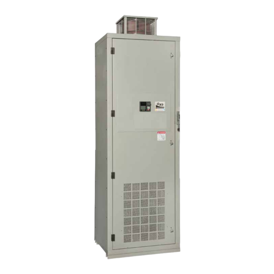
Page 250: Enclosure Dimensions/Weight
Lbs/kg Figure GX96 Junction Box No Junction Box 45/21 43/20 Figure 36 162/74 160/73 Figure 37 1450/658 1300/590 Figure 38 2350/1066 2250/1021 Figure 39 2560/1162 2330/1057 1700/772 1500/681 Figure 40 3500/1588 3200/1452 Figure 41 GX9 ASD Installation and Operation Manual... - Page 251 Figure 36. GX9 ASD 5.0 – 20 HP Enclosure. GX9 ASD Installation and Operation Manual...
- Page 252 Figure 37. GX9 ASD 25 – 75 HP Enclosure. GX9 ASD Installation and Operation Manual...
- Page 253 Figure 38. GX9 ASD 100 – 200 HP Enclosure. GX9 ASD Installation and Operation Manual...
- Page 254 Figure 39. GX9 ASD 250 – 400 HP Enclosure. GX9 ASD Installation and Operation Manual...
- Page 255 Figure 40. GX9 ASD 500 – 800 HP Enclosure. GX9 ASD Installation and Operation Manual...
- Page 256 Figure 41. GX9 ASD 900 – 1200 HP Enclosure. GX9 ASD Installation and Operation Manual...
-
Page 257: Gx9 Asd Optional Devices
GX9 ASD Optional Devices The GX9 ASD may be equipped with several options which are used to expand the functionality of the ASD. Table 18 lists the available options and their functions. Table 18. GX9 ASD Optional devices and functions. - Page 258 AM Terminal Adjustment, 194 Baud Rate (TTL), 199 Analog Filter, 48 Bezel Plate Mounting Hardware, 36 Analog Input Filter, 109 BIN Input Point 1 Frequency, 120 Analog Input Terminals, 47 BIN Input Point 1 Torque, 121 GX9 ASD Installation and Operation Manual...
- Page 259 160 Dynamic Braking Resistor Overload, 232 Control Margin Modulation for Current Vector Control, Dynamic Braking Selection, 132 Control Margin Modulation for Voltage Vector Control, Control Power Under-Voltage, 232 Cooling Fan Control, 188 E-10, 228 GX9 ASD Installation and Operation Manual...
- Page 260 ERR2, 229 Free Unit Multiplication Factor, 196 ERR3, 229 Free Unit Selection (Display Resolution), 197 ERR4, 229 ERR5, 229 Frequency at Trip, 41 ERR6, 229 Frequency Command Screen, 35 ERR7, 229 Frequency Command Source, 64 GX9 ASD Installation and Operation Manual...
- Page 261 Input Terminal 12 (LI4) Function, 91 Input Terminal 13 (LI5) Function, 92 LED/LCD Screen Information, 34 Input Terminal 14 (LI6) Function, 92 Light Load Conditions, 12 Input Terminal 15 (LI7) Function, 92 Light-Load High-Speed Operation Heavy-Load Detec- GX9 ASD Installation and Operation Manual...
- Page 262 Number of PG Pulses, 144 Mode Key, 33 MOFF, 225 MON1 Terminal Meter Adjustment, 195 MON1 Terminal Meter Selection, 195 MON2 Terminal Meter Adjustment, 195 OC, 225 MON2 Terminal Meter Selection, 195 OC1, 230 GX9 ASD Installation and Operation Manual...
- Page 263 Output Terminal 4 (OUT3) Function, 94 Output Terminal 5 (OUT4) Function, 94 PC/-, 17 Output Terminal 6 (R1) Function, 94 PG Disconnection Detection, 144 Output Terminal 7 (OUT5) Function, 95 PG Input Point 1 Frequency, 122 GX9 ASD Installation and Operation Manual...
- Page 264 Preset Speed 14, 129 RAM Fault, 229 Preset Speed 14 Direction, 149 Preset Speed 14 Start/Run Time, 180 Reach Settings, 47 Preset Speed 15, 129 Read Error, 229 Preset Speed 15 Direction, 149 real-time clock, 233 GX9 ASD Installation and Operation Manual...
- Page 265 RX Reference Point 1, 113 Speed Error, 228 RX Reference Point 2, 114 RX terminal, 22 Speed Limit (torque) Center Value Reference Selection, RX2, 42 RX2 Input Bias, 159 Speed Limit (torque=0) Band, 154 GX9 ASD Installation and Operation Manual...
- Page 266 Torque Limit Mode (Speed Dependent), 157 V/T2, 17 Torque Limit Settings, 53 Vector Motor Model, 55, 56 Torque Reference, 41 VI, 20 Torque Speed Limiting, 53 VI terminal, 22 Transducer Setup, 44 VI/II, 42 GX9 ASD Installation and Operation Manual...
- Page 267 Virtual Linear Pump Low Suction/No-Flow Cut Off De- lay Timer, 216 W/T3, 17 Virtual Linear Pump Low Suction/No-Flow Cut Off Warranty Card, 2 Fault Action, 216 Wizard Finish, 65 Virtual Linear Pump Low Suction/No-Flow Cut Off Mode, 215 W-Phase Over-Current, 231 GX9 ASD Installation and Operation Manual...
- Page 270 TOSHIBA TOSHIBA INTERNATIONAL CORPORATION INDUSTRIAL DIVISION 13131 West Little York Road, Houston, TX 77041-5807 US (800) 231-1412 CAN (800) 872-2192 MEX 01 (800) 527-1204 FAX: (713) 466-8773 http://www.toshiba.com/ind/ Printed in the U.S.A.
Need help?
Do you have a question about the GX9 and is the answer not in the manual?
Questions and answers