Table of Contents
Advertisement
Quick Links
Advertisement
Table of Contents

Subscribe to Our Youtube Channel
Related Manuals for Samcon ExCam Series T08


Summary of Contents for Samcon ExCam Series T08
- Page 1 Series ExCam ® - Installation Manual...
-
Page 2: Table Of Contents
Contents Introduction ......................4 Overview of the Device Documentation ..............5 Technical Data ......................6 Parameters of the Explosion Protection .............. 6 3.1.1 T08-VAx.x.x.x-X-X-X-X ......................6 3.1.2 T08-TNXCD-X-X-X-X ......................... 6 3.1.3 Conformity of Standards (Gas) ....................7 Maximum Electrical Parameters ................8 3.2.1 Power Supply .......................... - Page 3 List of illustrations Figure 10-1 T08-VAx.x.x.x mounting options ..............15 Figure 10-4 T08-TNXCD chain link mounting ..............16 Figure 10-7 Opening the ExCam T08-VAx.x.x.x .............. 18 Figure 10-8 Disassembly of the countersunk head screw type T08-TNXCD ....22 Figure 10-9 Opening of the cover flange type T08-TNXCD ..........23 Figure 10-10 Position of the O-Ring sealing type T08-TNXCD ........
-
Page 4: Introduction
Introduction The ExCam Series (Type 08) is an electrical device. It is certified according to ATEX, IECEx and EAC-Ex as a pressure-resistant camera system to be used in gas and dust explosive areas as well as in mines susceptible to firedamp. At the front side, the camera systems dispose of a flange with a sight glass (optical adapter);... -
Page 5: Overview Of The Device Documentation
Overview of the Device Documentation T08 ExCam Series (ATEX/ IECEx/ EAC-Ex) Ex Installation Manual This Dokument - EC - Declaration of Conformity - ATEX Type Examination - IECEx Certificate - EAC-Ex Certificate - Manufacturer Declaration (EN 60079-14) ExCam vario - User Manual - Datasheet ExCam niteZoom - User Manual... -
Page 6: Technical Data
Technical Data Parameters of the Explosion Protection 3.1.1 T08-VAx.x.x.x-X-X-X-X Identification marks according to directive 94/9/EC: II 2G (Zone 1 and 2) II 2D (Zone 21 and 22) I M2 Explosion protection (Gas): Ex d IIC T6 Gb or Ex d IIC T5 Gb or Ex d IIB T6 Gb or Ex d IIB T5 Gb or Explosion protection (Dust):... -
Page 7: Conformity Of Standards (Gas)
3.1.3 Conformity of Standards (Gas) Conformity of standards (Gas) IEC 60079-0:2011, EN 60079-0:2012 IEC 60079-1:2008, EN 60079-1:2008 IEC 60079-11:2011, EN 60079-11:2012 IEC 60079-18:2009, EN 60079-18:2009 IEC 60079-28:2006/ ISH1:2014, EN 60079-28:2007 (Beiblatt 1:2014-09) GOST R IEC 60079-0-2011 GOST IEC 60079-1-2011 Conformity of standards (Dust) IEC 60079-31:2008, EN 60079-31:2009 GOST R IEC 60079-31-2010 Notified body:... -
Page 8: Maximum Electrical Parameters
Maximum Electrical Parameters 3.2.1 Power Supply These are maximum values as part of the approval. Please refer to the device-specific values in the respective user manual! Type T08..: 12 … Power Supply: 60 V DC or 20 … 240 V AC 3.2.2 Power and Temperatures The below table 3-1 illustrates the maximum thermal supply input of all T08 ExCam hous-... -
Page 9: Other Technical Data
Other Technical Data Permitted temperature (storage) T08-VAx.x.x.x -60° C … +85° C (T T08-TNXCD -20° C … +80° C (T /with Viton O-ring -30° C … +80° C (T / with NBR 70 O-ring -50° C … +80° C (T / with VMQ- silicone O-ring Permitted ambient temperature: T08-VAx.x.x.x... - Page 10 Housing material: Stainless steel (non-corrosive / EN 10027-2) WNr.: 1.4301 (X5CrNi18-10), AISI 304 WNr.: 1.4305 (X8CrNiS18-9), AISI 303 WNr.: 1.4401 (X5CrNiMo17-12-2), AISI 316 WNr.: 1.4404 (X2CrNiMo17-12-2), AISI 316L WNr.: 1.4571 (X6CrNiMoTi17-12-2), AISI 316Ti Fitting for the flameproof gap (cylinder) according to DIN ISO 286-1 ����...
-
Page 11: General Safety Instructions
Attention! Only original parts of SAMCON Prozessleittechnik GmbH may be used for repairs. Repairs concerning the explosion protection may only be carried out in accordance with the nationally applied regulations and by SAMCON Prozessleittechnik GmbH. - Page 12 Attention! The instructions stated on the type and instruction plates have to be observed! Camera modules with autofocus: „WARNING – MAY NOT BE OPENED WHILE ENERGIZED.“ Adjustable camera modules or lenses: „WARNING – MAY NOT BE OPENED IN HAZARD AREAS.“ Note: Depending on the zone classification, it might be necessary to obtain a work permit/clearance! When adjusting the camera settings potentially explosive atmosphere must be avoided by any means!
-
Page 13: Application
The information in chapter 3 and 4 has to be considered during operation. Without a written statement of Samcon Prozessleittechnik GmbH, the equip- ment may not be used for applications differing from the described and intended ones. -
Page 14: Transportation And Storage
Transportation and Storage Avoid impacts Check the equipment regarding possible damages at the packaging or the camera Store the camera in its original packaging and in a dry and weatherproof place un- til installation Avoid exposing the equipment to extreme heat or cold Installation The national regulations and accepted rules of technology are decisive for the installation and operation of the camera. -
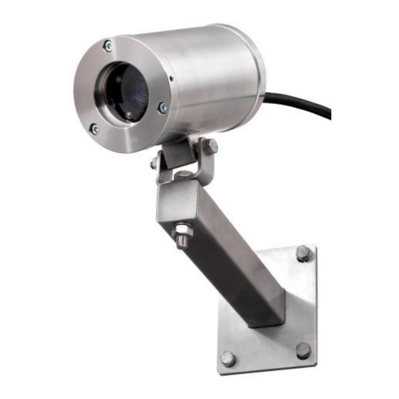
Page 15: Type T08-Vax.x.x.x
7.1.1 Type T08-VAx.x.x.x For the observation of plants and/or persons, the camera can be installed on a rotatable installation bracket (accessory). The pin which is laterally welded to the housing is in- tended for this purpose and disposes of a 6.5 mm or an 8.5 mm drilling. The wall mount bracket is available in different dimensions and may be installed in any position which is allowed by the four available drillings. -
Page 16: Type T08-Tnxcd
7.1.2 Type T08-TNXCD The PTZ camera type T08-TNXCD is mounted in a hanging manner (transparent dome copula facing downwards). For installing the dome camera at the wall, the six M8x1.25 threaded holes located at the cover flange and correspondingly at the wall mount bracket with L-profile (accessories) can be used. -
Page 17: Opening And Closing Of The Unit
The T08 ExCam Series may exclusively be opened due to functional aspects and when the applicable user manual explicitly allows it. For all other purposes, the explosion proof housing may only be opened and closed by authorized personnel of SAMCON Prozess- leittechnik GmbH. -
Page 18: Figure 10-7 Opening The Excam T08-Vax.x.x.x
The following has to be observed: Prior to opening the housing of the type T08-VAx.x.x.x it might be necessary to demount the hood or other accessory. The housing must only be opened on the rear flange of the cable and supply flange. - Page 19 Pull out very carefully the lead flange in a straight manner (q.v. figure 10-7) , ensuring that it does not tilt. Due to the created lower pressure, this might require some addi- tional effort The cylindrical clearance fit (H8f7 - DIN ISO 286) of the body as well as of the flange components must not be tilted as this runs the risk of damaging the flame proof gap pre-venting the transmission of ignition (DIN EN 60079-1:2008)! Avoid skin or clothing contact at the cylindrical fit as it disposes of oleaginous fit-...
- Page 20 Attention! In case the flameproof joint has been damaged mechanically, the housing must not be used anymore! Attention! Do not lock-in any foreign objects inside the housing Only the original screws as part of the delivery scope may be used. They have to be clean and intact.
-
Page 21: Type T08-Tnxcd
If, when looking through the transparent polycarbonate dome cupola a damage, irregular- ities, or alterations such as loose parts, discoloring, or liquid inclusion (not water conden- sation!) are visible inside the ExCam, SAMCON Prozessleittechnik GmbH has to check the camera. -
Page 22: Figure 10-8 Disassembly Of The Countersunk Head Screw Type T08-Tnxcd
The housing must only be opened at the rear flange of the cable and supply flange. It is not allowed to remove the optic-adapter In order to open the housing, the body has to be fixed. The cover flange with the cable (pig tail) has to remain flexible (e.g. -
Page 23: Figure 10-9 Opening Of The Cover Flange Type T08-Tnxcd
Figure 10-9 Opening of the cover flange type T08-TNXCD The metric fine thread (M188x1.5/ larger 5 supporting thread holes / quality 6g) lo- cated at the flange as well as body component may not be damaged! Danger through damaging t he flame proof gap preventing the transmission of ignition (DIN EN 60079-1:2008)! Avoid skin or clothing contact at the cylindrical fit as it disposes of oleaginous fit- ting compound (MOLYKOTE P-40) to protect the surface for frictional corrosion... - Page 24 After completion of the measures, the housing has to be closed again immediate- ly. Do not lock-in any foreign objects! For closing the housing, please follow, in reversed order, the steps described for the opening of the housing. Please observe the following warning instructions : Attention! Make sure to completely insert the flange in order to guarantee the ig- nition protection type and the housing IP protection level...
-
Page 25: Electrical Connection And Commissioning
Electrical Connection and Commissioning Attention! The electrical connection of the device may only be carried out by qualified personnel The electrical connection and commissioning must be executed in accordance with na- tional regulations by authorized personnel only. Please note the electrical connection specifications of the device user manual! Attention! ®... -
Page 26: Maintenance/ Modification
Reparation Reparations must only be carried out with original parts of SAMCON Prozessleittechnik GmbH. Damaged pressure-resistant casing should be replaced completely. In case of doubt, send the part in question back to SAMCON Prozessleittechnik GmbH. -
Page 27: Certificates
Certificates EC – declaration of conformity 11.1 Doc.-ID: 140721-PT08BAU-SS-Ex Installation Manual rev.03 (1st Supplement), page 27 of 52... -
Page 28: Manufacturer's Declaration Concerning The Cable And Cable Entry Points
Manufacturer’s declaration concerning the cable and cable entry points 11.2 Doc.-ID: 140721-PT08BAU-SS-Ex Installation Manual rev.03 (1st Supplement), page 28 of 52... -
Page 29: Ec-Type Examination Certificate
11.3 EC-Type Examination Certificate Doc.-ID: 140721-PT08BAU-SS-Ex Installation Manual rev.03 (1st Supplement), page 29 of 52... - Page 30 Doc.-ID: 140721-PT08BAU-SS-Ex Installation Manual rev.03 (1st Supplement), page 30 of 52...
- Page 31 Doc.-ID: 140721-PT08BAU-SS-Ex Installation Manual rev.03 (1st Supplement), page 31 of 52...
- Page 32 Doc.-ID: 140721-PT08BAU-SS-Ex Installation Manual rev.03 (1st Supplement), page 32 of 52...
- Page 33 Doc.-ID: 140721-PT08BAU-SS-Ex Installation Manual rev.03 (1st Supplement), page 33 of 52...
- Page 34 Doc.-ID: 140721-PT08BAU-SS-Ex Installation Manual rev.03 (1st Supplement), page 34 of 52...
- Page 35 Doc.-ID: 140721-PT08BAU-SS-Ex Installation Manual rev.03 (1st Supplement), page 35 of 52...
-
Page 36: Iecex Certificate Of Conformity
11.4 IECEx Certificate of Conformity Doc.-ID: 140721-PT08BAU-SS-Ex Installation Manual rev.03 (1st Supplement), page 36 of 52... - Page 37 Doc.-ID: 140721-PT08BAU-SS-Ex Installation Manual rev.03 (1st Supplement), page 37 of 52...
- Page 38 Doc.-ID: 140721-PT08BAU-SS-Ex Installation Manual rev.03 (1st Supplement), page 38 of 52...
- Page 39 Doc.-ID: 140721-PT08BAU-SS-Ex Installation Manual rev.03 (1st Supplement), page 39 of 52...
- Page 40 Doc.-ID: 140721-PT08BAU-SS-Ex Installation Manual rev.03 (1st Supplement), page 40 of 52...
- Page 41 Doc.-ID: 140721-PT08BAU-SS-Ex Installation Manual rev.03 (1st Supplement), page 41 of 52...
- Page 42 Doc.-ID: 140721-PT08BAU-SS-Ex Installation Manual rev.03 (1st Supplement), page 42 of 52...
- Page 43 Doc.-ID: 140721-PT08BAU-SS-Ex Installation Manual rev.03 (1st Supplement), page 43 of 52...
-
Page 44: Eac-Ex Certification
11.5 EAC-Ex Certification Doc.-ID: 140721-PT08BAU-SS-Ex Installation Manual rev.03 (1st Supplement), page 44 of 52... - Page 45 Doc.-ID: 140721-PT08BAU-SS-Ex Installation Manual rev.03 (1st Supplement), page 45 of 52...
- Page 46 Doc.-ID: 140721-PT08BAU-SS-Ex Installation Manual rev.03 (1st Supplement), page 46 of 52...
- Page 47 Doc.-ID: 140721-PT08BAU-SS-Ex Installation Manual rev.03 (1st Supplement), page 47 of 52...
-
Page 48: Drawings
Drawings Equipment drawings can be found in the individual datasheets. DXF files, 3D models, drawings of accessories can be found at www.samcon.eu For additional information, please contact us at support@samcon.eu Doc.-ID: 140721-PT08BAU-SS-Ex Installation Manual rev.03 (1st Supplement), page 48 of 52... -
Page 49: Notes
Notes Doc.-ID: 140721-PT08BAU-SS-Ex Installation Manual rev.03 (1st Supplement), page 49 of 52... - Page 50 Doc.-ID: 140721-PT08BAU-SS-Ex Installation Manual rev.03 (1st Supplement), page 50 of 52...
- Page 51 Doc.-ID: 140721-PT08BAU-SS-Ex Installation Manual rev.03 (1st Supplement), page 51 of 52...
- Page 52 Schillerstrasse 17, 35102 Lohra-Altenvers www.samcon.eu, info@samcon.eu fon: +49 6426 9231-0, fax: - 31 Doc.-ID: 140721-PT08BAU-SS-Ex Installation Manual rev.03 (1st Supplement), page 52 of 52...
Need help?
Do you have a question about the ExCam Series T08 and is the answer not in the manual?
Questions and answers