
Subscribe to Our Youtube Channel
Related Manuals for Samcon ExCam IP1354


Summary of Contents for Samcon ExCam IP1354
- Page 1 IP13xx ExCam User manual Digital unterschrieben von Steffen Seibert DN: cn=Steffen Seibert, o=SAMCON, ou, email=s.seibert@samcon.eu, c=DE Datum: 2017.03.15 09:48:55 +01'00'...
-
Page 2: Table Of Contents
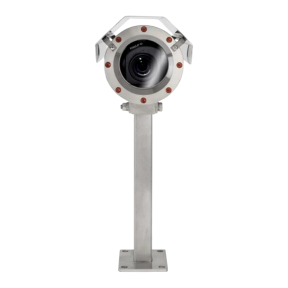
Content Introduction ......................5 Technical Data ......................6 Parameters of the explosion protection ............... 6 Electrical parameters of the camera ..............7 2.2.1 Axis P1354 ..........................7 2.2.2 Axis P1357 ..........................7 2.2.3 Axis P1364 ..........................7 2.2.4 Axis P1365 ..........................7 2.2.5 Axis P1365 MkII ......................... - Page 3 Table of Figures Figure 1.1 – ExCam IP13xx Series with wall mount bracket and roof ....... 5 Table 4.1 – Model key ..................... 16 Figure 5.1 – ExCam IP13xx potential equalization ............19 Table 5.1 – Potential equalization ..................19 Figure 5.2 –...
-
Page 4: Author: Thiemo Gruber
Compilation of the document based on „140808-PT08BA-TG-ExCam IP1354_en_rev.02.docx“, Revision of Reviewed and approved the title and content / re-naming of the October xx, 2014 – S. Seibert ExCam IP1354 user manual into ExCam IP135x Series December 05, 2014 S.Seibert Revision and approval Reviewed and approved December 05, 2014 –... -
Page 5: Introduction
Introduction The ExCam IP13xx Series is a camera system (type 08) manufactured by SAMCON Prozessleittechnik GmbH which can be used for various applications, preferably within hazardous areas of the chemical and/or petro-chemical industry, at offshore plants, in mines, and at biogas plants. -
Page 6: Technical Data
Technical Data Parameters of the explosion protection Identification marks according to Directive 94/9/EG (until Apr 20, 2016): Directive 2014/34/EU: II 2G (zone 1 and 2) II 2D (zone 21 and 22) I M2 Explosion protection (gas): Ex d IIC T6 Gb or Ex d IIC T5 Gb or Ex d IIB T6 Gb or Ex d IIB T5... -
Page 7: Electrical Parameters Of The Camera
Electrical parameters of the camera 2.2.1 Axis P1354 Power supply: PoE, IEEE 802.3af class 3 Reference power: ±48 V DC (44...54 V DC) Maximum power input: 7.2 W 2.2.2 Axis P1357 Power supply: PoE, IEEE 802.3af class 3 Reference power: ±48 V DC (44...54 V DC) Maximum power input: 7.9 W... -
Page 8: Electrical Parameters Of The Heating (Optional)
Electrical parameters of the heating (optional) Reference power U 24 V DC ≥ -30°) Nominal power P 20 W for type L (T ≥ -60°) 40 W for type L (T Attention! The power consumption of the housing heating is determined by the ambient tempera- found in the modules’... -
Page 9: System Cable Skd02-T
System cable SKD02-T Samcon System Cable Digital (type „SKD02-T“) Description: for low temperature ranges, data transfer and power supply of the camera modules M1145 and M1145-L (DIN EN 60079-14: 2014 con- form) Sheath color: Yellow-green (GN), similar RAL6018 Ex d marshalling:... -
Page 10: Supply Cable (Optional)
User interface: P(Plug) version: RJ-45 Stecker (EIA/TIA- 568B), e.g. Weidmüller IE-PS-RJ45-FH-BK, Phoenix Contact VS-08-RJ45-5-Q/IP20 etc., 10BASE-T/100BASE-TX PoE K(terminal block) version: about 12 cm stripped: 8 x single conductors twisted pair (solid conduc- tor A=0.33mm , ø=0.64 mm approx. 6 mm stripped), 1 x shield (Cu braid tinned 1.5 mm ferule color code according to DIN 46228) 10BASE-T/ 100BASE-TX PoE... -
Page 11: Technical Specification Of The Camera Module
UV re- sistant, additional testing requirements accord- ing to IEC 60811, EN 50396 and EN 50396 (q.v. www.samcon.eu, data sheet Ölflex 440P) Conductor identification code: Black conductors with white numbers with GN/YE- protective earth according to DIN EN... -
Page 12: Axis P1354
2.6.1 Axis P1354 User manual: http://www.axis.com/files/manuals/um_p1354_1463736_en_1505.pdf 2.6.2 Axis P1357 Data sheet: http://www.axis.com/files/datasheet/ds_p1357_1471705_en_1505.pdf User manual: http://www.axis.com/files/manuals/um_p1357_1465567_en-1506.pdf 2.6.3 Axis P1364 Data sheet http://www.axis.com/files/datasheet/ds_p1364_1511096_en_1512.pdf User manual: http://www.axis.com/files/manuals/um_p1364_1510439_en_1601.pdf 2.6.4 Axis P1365 Data sheet: http://www.axis.com/files/datasheet/ds_p1365_60562_en_1503_hi.pdf User manual: http://www.axis.com/files/sales/um_p1365_1489706_en_1507.pdf 2.6.5 Axis P1365 Mk Data sheet http://www.axis.com/files/datasheet/ds_p1365mkii_60562_en_1603.pdf User manual: http://www.axis.com/files/manuals/um_p1365mkii_1489706_en_1604.pdf Doc.-ID: 141021-PT08BA-TG-ExCam IP13xx Series_en_rev.03, page 12 of 44... -
Page 13: Other Technical Data
Other technical data Permitted ambient -10 °C … +50 °C (Type N / P1365) temperature (MTBF) -10 °C ….+40 °C (Type N / P13xx) -30 °C … +40 °C (Type L) -60 °C … +40 °C (Type LL) Protection level EN 60529/ IEC 529: IP68 Test conditions (>IP67): 24h/ 3m water column, pH-neutrality, temperature of the liquid medium:... - Page 14 Protective coating Standard color RAL7035 (all RAL colors and special colors possible!), DURALMIT® 2K-PUR structure, type DSPT (isocyanate netted, polyester modified acrylate resin, fine structure (1.6…2.0 [mm] nozzle), surface re- sistance ≤ 9^11[Ω], layer thickness ≤ 0.2 [mm], screw connections, flat gaskets and cable glands are excluded from the coating Additional metallic/non-metallic materials of the Ex d housing protection system:...
- Page 15 800 g (Twin adapter WMB-xTA) 750 g (Hood WPR-VA2.1) 100 g (Hinge attachment SCH-VA2.x) 450 g (clamp attachment CMB-S) 1200 g (Samcon cool.Jacket VA2.2) Further accessories upon request! Dimension (wxhxd) 113.0 mm x 138.5 mm x 260.2 mm (K1 flange) 113.0 mm x 138.5 mm x 276.0 mm (K2 flange)
-
Page 16: Safety Guidelines
The following model options are currently available for the ExCam IP13xx Series: Model options Type Housing Cable length/m Cable Temperature Ex product name Gas expl. combination SKD02-T/Ölflex termin. range group 440P ExCam IP1354, T08- VA2.2.K1.BOR- 005- ExCam IP1357, T08- VA2.2.K1.BOR- 005- ExCam IP1364, T08- VA2.2.K2.BOR- 005- ExCam IP1365 T08- VA2.2.K2.BOR- 005- ) …... - Page 17 005 = Length of the connection line in meter at delivery. The standard cable length is 5 m (minimum/maximum cable length: 001…100 [m]) Information: According to DIN EN 60079-14:2014 [chapter 10.6.2]) it is, at a cable length of ≥ 3 m, possible to use cable glands without an integrat- ed pressure barrier as well as an elastomer sealing on the outer sheath and an additional strain relief.
-
Page 18: Commissioning
Commissioning Attention! Please observe the national regulations regarding security, installa- tion, and accident prevention (e.g. DIN EN 60079-14 or DIN VDE 0118- 1:2010-02) for the erecting of electrical plants in mining etc.) as well as the safety guidelines described in this user manual and the EX instal- lation manual! Attention! Please observe the installation and commissioning advices described... -
Page 19: Potential Equalization
® The ExCam IP13xx Series is delivered with the electrical connection cable type SKD02- T suitable for the hazardous area. Optionally, the camera can dispose of a power cable (standard is a type „Ölflex® 440P“).The maximum cable length is 100 m (depending on electromagnetic tolerance) and can be determined individually to reflect the particular customer specifications. -
Page 20: Connection And Protection
5.2.2 Connection and protection Cable gland 2 (optional) Ölflex® 440P – Power supply for CB06 circuit board, PTC heating Cable gland 1 elements and further devices if SKD02-T - digital video applicable via a relays control stream, control and power (build-to-order) supply (PoE) of the camera module... -
Page 21: Figure 5.4 - Excam Ip13Xx T08-Va2.2.K1.Bor-C-Xxx-P-N
Figure 5.4 – ExCam IP13xx T08-VA2.2.K1.BOR-C-XXX-P-N Figure 5.5 – ExCam IP13xx T08-VA2.2.K1.BOR-CB-XXX-P(K)-L(L)(H) Via the 8 (+1) -wire green patch cable SKD02-T, the communication and the data transfer to connected network devices as well as the power supply (PoE) of the camera is carried out. - Page 22 5.2). Generally, the pins of the same color code (IEC60757) are connected. Attention: The general specification for PoE allows different operation modes for PDs (ExCam IP1354, ExCam IP1357, ExCam IPQ1775 etc.): Mode A (end span): This is usually used by switches; the supply voltage is executed as phantom power on the data lines.
-
Page 23: Figure 5.6 - Rj45 Contact Assignment
n.a. PoE GND WH / BN 0,33 0.64 Solid conductor Cu blank n.a. PoE GND 0,33 0.64 Solid conductor Cu blank shield/ GND Shield braid of (complete conductor bunch) tinned copper wires Ø=0.13 (AWG 36) shield n/a / 10 Aluminum syn- (single, twisted pair pins) thetic strapp, twisted... -
Page 24: Tests Prior To Switching On Voltage
In case the ExCam IP13xx is supplied via a PoE capable device, an additional safe- guarding of the power supply is not necessary. The power supply is executed by the PoE network device via an electronic with intelligent set-up. The camera as well as the con- nection is permanently monitored in order to avoid any failure or defects in case of a short-circuit fault. -
Page 25: Testing Of The Status Led
Testing of the status LED Through the sight glass, the status LED is visible. Prior to accessing the camera via the web interface, the proper functioning of the camera should be tested. The booting pro- cess of the ExCam IP13xx can take up to one minute. Additional LEDs for checking net- work activities or the bandwidth are only visible when the housing is open. -
Page 26: Step 3: Adjusting The Lens
Step 3: Adjusting the lens This step is only required in case the default settings of the picture or the user settings carried out via the web interface (focus assistant, sharpness, digital zoom etc.) do not deliver the desired results. If so, the focus (sharpness) as well as the angle of view (tele) has to be readjusted. -
Page 27: Work Preparation
5.4.1 Work preparation Attention! Please carry out any preoperational work carefully and in accordance with the applicable regulations. Attention: Note: Depending on the zone classification, it might be necessary to obtain a work permit/clearance! When adjusting the camera settings potentially explosive atmosphere must be avoided by any means! Please consider that in order to carry out the applicable settings, a feedback regarding the picture quality is required. -
Page 28: Figure 5.8 - Removing The Protection Roof (1/2)
Figure 5.8 – Removing the protection roof (1/2) Figure 5.9 – Removing the protection roof (2/2) To open the enclosure (T07 VA2.2) of the ExCam IP13xx Series, loosen the four hexa- gon socket screws (DIN 912/ ISO 4762) located at the cable gland flange of the stainless steel housing, including the washer springs (DIN 127 A) (q.v. -
Page 29: Figure 5.10 - Opening The Excam Ipxxx
Figure 5.10 – Opening the ExCam IPxxx Pull out very carefully the lead flange in a straight manner, ensuring that the board mod- ule does not tilt. Due to the created lower pressure, this might require some additional effort. The cylindrical clearance fit (H8f7 - DIN ISO 286) of the body as well as flange components must not be tilted as this runs the risk of damaging the flame proof gap pre- venting the transmission of ignition (DIN EN 60079-1:2012)! Attention: The mounting adapter with the PTC heating module, the camera module, and... -
Page 30: Adjusting The Focus And Angle
5.4.3 Adjusting the focus and angle The default focus of ExCam IP13xx network camera is set to an object distance of ap- proximately 10 m; the angle is set to the maximum wide range. Depending on the indi- vidual camera module, this angle can range between 92° - 109°. Usually it is not neces- sary to carry out any adaptions. -
Page 31: Extracting/Inserting An Sd Storage Card
Sharpness controller (focus) Zoom controller (tele) Figure 5.12 – Mechanical adjustments at the lens 5.4.4 Extracting/inserting an SD storage card The ExCam IP13xx disposes of a slot for a microSDHC storage card. Saved video files can be viewed or deleted via the web interface; they are also available in a download list or as an ftp file to the network. -
Page 32: Hardware Reset
Please pay attention when inserting / extracting the storage card. Do not damage the connection cable, terminals, or the CB06 circuit board! Do not bend the aluminum mounting adapter as otherwise the optical axis of the equipment and hence the picture quality is not guaranteed anymore! When touching electrical components, potential equalization (ground- ing of the body) has to be observed (ESD clothing, PE wristband etc.)! - Page 33 Attention! In case the flameproof joint has been damaged mechanically, the housing must not be used anymore! Attention! Do not lock-in any foreign objects inside the housing Please make sure that the disassembled screw locks (washer spring DIN 127A) are re- assembled.
-
Page 34: Network Access And Visualization
For a comprehensive user manual of the web surface, please refer to the to the Axis user manual which can be found on the provided storage medium or which can be accessed at: ExCam IP1354 http://www.axis.com/de/files/manuals/um_p1354_51348_en_1303.pdf ExCam IP1357 http://www.axis.com/de/files/manuals/um_p1357_49958_en_1303.pdf... -
Page 35: Assigning The Ip Address
With the “AXIS IP Utility“ tool it is possible to determine the IP address with Windows; the included storage medium contains this application. It is also available for download: http://www.samcon.eu/downloads-ex-videokameras-atex/download-treiber-software/ In case it is not possible to assign the IP address, it might be necessary to change the firewall settings! The “AXIS IP Utility“... -
Page 36: Password / Identification
Password / identification The default user name is: root The default password is: root When a system reset of the equipment has been carried out, please follow the instruc- tions below: In order to allow access to the camera, the password for the standard administrator user „root“... -
Page 37: Maintenance / Servicing / Alterations
Repairs and Maintenance Repairs must only be carried out with original parts of SAMCON Prozessleittechnik GmbH. Damaged pressure-resistant housings have to be replaced completely. If in doubt, return the applicable part to SAMCON Prozessleittechnik GmbH. -
Page 38: Drawings
Drawings Attention: The technical drawings show T08 ExCam IP13xx cameras and integrated pressure barrier within the cable gland (compound grouting of the single conductors). The design shows the maximum dimen- sions! For cable glands with elastomer sealing of the outer sheath the dimensions in the depth is reduced by 30 mm! T08-VA2.2.K1.BOR-C-XXX-X-L(L) Figure 10.1 –... -
Page 39: Figure 10.2 - Dimensions Of The T08 Excam Ip13Xx With K2 Flange
T08-VA2.2.K2.BOR-C-XXX-X-N Figure 10.2 – Dimensions of the T08 ExCam IP13xx with K2 flange Doc.-ID: 141021-PT08BA-TG-ExCam IP13xx Series_en_rev.03, page 39 of 44... -
Page 40: Figure 10.3 - Dimensions Of The T08 Excam Ip13Xx With Accessories
T08-VA2.2.K1.BOR-C-XXX-X-L(L) with accessories Figure 10.3 – Dimensions of the T08 ExCam IP13xx with accessories Doc.-ID: 141021-PT08BA-TG-ExCam IP13xx Series_en_rev.03, page 40 of 44... -
Page 41: Notes
Notes Doc.-ID: 141021-PT08BA-TG-ExCam IP13xx Series_en_rev.03, page 41 of 44... - Page 42 Doc.-ID: 141021-PT08BA-TG-ExCam IP13xx Series_en_rev.03, page 42 of 44...
- Page 43 Doc.-ID: 141021-PT08BA-TG-ExCam IP13xx Series_en_rev.03, page 43 of 44...
- Page 44 Schillerstrasse 17, 35102 Lohra-Altenvers www.samcon.eu, info@samcon.eu fon: +49 6426 9231-0, fax: - 31 Doc.-ID: 141021-PT08BA-TG-ExCam IP13xx Series_en_rev.03, page 44 of 44...
Need help?
Do you have a question about the ExCam IP1354 and is the answer not in the manual?
Questions and answers