
Subscribe to Our Youtube Channel
Related Manuals for Brainchild P41


Summary of Contents for Brainchild P41
- Page 1 User's Manual User's Manual DIN EN ISO 9001 Certificate: 01 100 98505 LISTED P41 / P91 P41 / P91 Auto-Tune Fuzzy / PID Auto-Tune Fuzzy / PID Profiling Controller Profiling Controller UM0P411D...
- Page 2 12 and later version. Copyright Copyright February 2007, The Brainchild Corporation, all rights February 2007, The Brainchild Corporation, all rights reserved. No part of this publication may be reproduced, transmitted, reserved. No part of this publication may be reproduced, transmitted,...
-
Page 3: Table Of Contents
Contents Page No Page No Chapter 1 Overview Chapter 1 Overview Chapter 4 Profiler Operation Chapter 4 Profiler Operation 1-1 General ------------------------- 5 4-1 What is set point profiler --- 1-2 Ordering Code ---------------- 9 4-2 Segment connection ------- 1-3 Programming Port ---- ----- 11 4-3 Profiler Modes --------------- 1-4 Keys and Displays ----------12 4-4 Running, holding and ----------... - Page 4 2.1 Mounting Dimensions --------------------------------------------------------------------------------- 33 igure 2.2 Lead Termination for P41------------------------------------------------------------------------------ 34 igure 2.3 Lead Termination for P91------------------------------------------------------------------------------ 34 igure 2.4 Rear Terminal Connection for P41 -------------------------------------------------------------------35 igure 2.5 Rear Terminal Connection for P91 ------------------------------------------------------------------ 35 igure 2.6 Power Supply Connections -------------------------------------------------------------------------- 36 igure 2.7 Sensor Input Wiring ------------------------------------------------------------------------------------ 36...
-
Page 5: Chapter 1 Overview
P91 is a 1/16 DIN size panel mount profiling controller. It can also be used for rail mount by adding a rail mount kit. P41 is a 1/4 DIN size panel mount profiling controller. - Page 6 PID control with properly tuned PID + Fuzzy control Temperature point Figure 1.1 Figure 1.1 Fuzzy Control Fuzzy Control Advantage Advantage Load Disturbance Warm Up Time The series can be configured as a single set point controller (static mode) or a ramp and dwell profiling controller (profile mode). The profile mode feature allows the user to program up to 9 profiles of up to 64 free-format (ramp, dwell, jump or end) segments each.
- Page 7 Analog Retransmission Analog Retransmission The output 5 and output 4 (P41 only) of the products can be equipped with analog output module. The output can be configured for transmitting the process value as well as set point value.
- Page 8 Programming Port Programming Port A programming port is used to connect the unit to a hand-held programmer or a PC for quick configuration, also can be connected to an ATE system for automatic testing & calibration. Auto-tune The auto-tune function allows the user to simplify initial setup for a new system.
-
Page 9: Ordering Code
1-2 Ordering Code 1-2 Ordering Code P41- P91- Standard leave blank Standard leave blank Power Input Power Input Special Order AA-ZZ Special Order AA-ZZ 4: 90 - 250 VAC, 47-63 Hz 4: 90 - 250 VAC, 47-63 Hz Options 5: 11 - 26 VAC or VDC,... - Page 10 RK91-1 = Rail Mount kit for BTC-9100 / P91 RK91-1 = Rail Mount kit for BTC-9100 / P91 DC21-1 = Isolated 20V/25mA DC Output Power Supply for P41 Output 5 DC21-1 = Isolated 20V/25mA DC Output Power Supply for P41 Output 5...
-
Page 11: Programming Port
1-3 Programming Port 1-3 Programming Port Front Rear Terminal Panel Figure 1.2 Figure 1.2 Programming Port Programming Port " Overview Overview Access Hole Access Hole A special connector can be used to touch the programming port which is connected to a PC for automatic configuration, also can be connected to an ATE system for automatic calibration and testing. -
Page 12: Keys And Displays
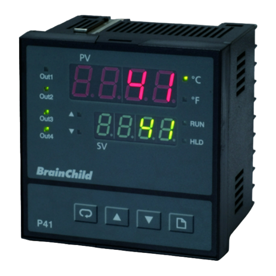
1- 4 Keys and Displays 1- 4 Keys and Displays KEYPAD OPERATION KEYPAD OPERATION SCROLL KEY : SCROLL KEY : This key is used to select a parameter to be viewed or adjusted. UP KEY : UP KEY : This key is used to increase the value of selected parameter. DOWN KEY : DOWN KEY : This key is used to decrease the value of selected parameter. - Page 13 Upper Display, to display process value, menu symbol and error code etc. Output Status indicators for Lower Display, to display set point value, output1~output 4 parameter value or control output value etc. On : profile running Out1 Flashing: profile in delayed state LF LF Out2 On : profile held...
- Page 14 2.5 seconds during power up. LF LF Out2 The display shows program number 37 with program version 12. Out3 The program no. for P41 is 37 and for Out4 P91 is 38. Figure 1.4 Figure 1.4 Program code display...
-
Page 15: Key Operation Flowchart
1-5 Key Operation Flowchart 1-5 Key Operation Flowchart Mode Page Mode Page Profile Page Profile Page Home Page Home Page Home Home Display Display ( 1-9 ) (MODE) (Profile run mode) (Profile hold mode) (Static mode) (Automatic tuning PID1 mode) TIME (Automatic tuning PID2 mode) (Manual mode) - Page 16 High High Calibration Calibration Calibration Calibration Configuration Configuration Page Page Page Page Page Page 5 sec. 5 sec. (CALO) (CAHI) INPT UNIT (OFSTL) (OFSTH) INLO INHI Using key to Using key to FILT adjust the offset low value adjust the offset high value EIFN (lower display) until the (lower display) until the...
-
Page 17: Parameter Descriptions
1-6 Parameter Descriptions 1-6 Parameter Descriptions Register Parameter Default Data Parameter Description Range Address Notation Value type Controller (Static mode) 25.0 C Low: SPLO High: SPHI Set point value (77.0 F) Low: 1.00 High: 9.63 Indicate the current PFSG Profile/Segment 1.00 Profile number number... - Page 18 Parameter Register Parameter Default Data Range Description Address Notation Value type : 4 - 20 mA linear current input : 0 - 20 mA linear current input : 0 - 60 mV linear millivolt input Input sensor INPT : 0 - 1V linear selection voltage input : 0 - 5V linear...
- Page 19 Parameter Register Parameter Default Data Range Description Address Notation Value type 0 second time constant 0.2 second time constant 0.5 second time constant 1 second time constant 2 seconds time constant FILT Filter damping 5 seconds time time constant constant of PV 10 seconds time constant...
- Page 20 Parameter Register Parameter Default Data Range Description Address Notation Value type Select BPLS ( bumpless transfer ) or 0.0 ~ 100.0 % to O1FT Output 1 failure continue output 1 control transfer status function as the unit fails, or select OFF (0) or ON (1) for ON-OFF control.
- Page 21 : No function : Alarm 3 output : Reverse alarm 3 output OUT4 : Event 3 output Output 4 function (for P41 only) : Retransmit process value : Retransmit set point value : DC power supply output UM0P411A...
- Page 22 Value type : Output 4 OFF Output 4 failure O4FT as unit fails transfer status : Output 4 ON (for P41 only) as unit fails Low limit value for Low: 0 High: 100.0 % OP4L output 4 (for P41 only)
- Page 23 Parameter Register Parameter Default Data Range Description Address Notation Value type 2.4 Kbits/s baud rate 4.8 Kbits/s baud rate 9.6 Kbits/s baud rate BAUD Baud rate of digital communication 14.4 Kbits/s baud rate 19.2 Kbits/s baud rate 28.8 Kbits/s baud rate 38.4 Kbits/s baud rate : Even parity PARI...
- Page 24 : Deviation high alarm : Deviation low alarm ALF3 ALF3 Alarm 3 function : Deviation band (for P41 only) high/low alarm : End of profile alarm : Hold mode alarm : Static mode alarm : Normal alarm action : Latching alarm action...
- Page 25 Hysteresis control A3HY 0.1 C High: 50.0 C for alarm 3 Low: 0.1 (90.0 F) (0.2 F) (for P41 only) Reserved : No parameter selected : INPT selected for home page : UNIT selected for home page : DP selected for...
- Page 26 Parameter Register Parameter Default Data Range Description Address Notation Value type Select 4'th SEL4 parameter Same as SEL1 for home page Select 5'th SEL5 parameter Same as SEL1 for home page Select 6'th SEL6 parameter Same as SEL1 for home page Select 7'th SEL7 parameter...
- Page 27 Parameter Register Parameter Default Data Range Description Address Notation Value type : Continue profile from the last set point value : Start to run from PV Power fail recovery : Static mode, SP1 : OFF mode Low : 0.00 High : 99.59 Holdback wait 1.00 (hour.minute)
- Page 28 Parameter Register Parameter Default Data Range Description Address Notation Value type Time duration or RTRR Ramp rate for Low: 0 High: 5999 ramp segment Four-bit binary number ( 0=inactive 1=active ) States assignment of PID selection P2EV and event outputs Event 1 for ramp, and Event 2...
- Page 29 Parameter Register Parameter Default Data Range Description Address Notation Value type RTD calibration Low: -1999 high: 1999 RTDL low coefficient RTD calibration Low: -1999 high: 1999 RTDH high coefficient Cold junction CJLO calibration low Low: -5.00 high: 40.00 coefficient Cold junction Low: -1999 high: 1999 CJHI...
- Page 30 Parameter Register Parameter Default Data Range Description Address Notation Value type Reserved Reserved Reserved Reserved Reserved Low: -32768 High: 32767 Process value Set point value for Low: SPLO High: SPHI control Output 1 percentage Low: 0.00 High: 100.00 value (Heating ) Output 2 percentage Low: 0.00...
- Page 31 Parameter Register Parameter Default Data Range Description Address Notation Value type Set point for Low:SPLO High: SPHI SPSG current segment Time remaining for the current Low:00.00 High: 99.59 TIME segment Cycle remaining Low:1 High: 9999 for the current CYCL 10000=infinite loop Program and version code...
-
Page 32: Chapter 2 Installation
Chapter 2 Installation Chapter 2 Installation Dangerous voltages capable of causing death are sometimes Dangerous voltages capable of causing death are sometimes present in this instrument. Before installation or beginning any present in this instrument. Before installation or beginning any cleaning or troubleshooting procedures the power to all equipment cleaning or troubleshooting procedures the power to all equipment must be switched off and isolated. - Page 33 Figure 2.1 Mounting Dimensions Figure 2.1 Mounting Dimensions Panel Cutout Panel 92 mm 53 mm Panel 45 mm Panel Cutout Panel Mount Panel Mount 11.5mm 104.8mm 7.5mm 62.0mm 48.0mm Rail Mount Rail Mount 104.8mm 11.5mm 6.5mm UM0P411A...
-
Page 34: Wiring Precautions
2 - 3 Wiring Precautions 2 - 3 Wiring Precautions Before wiring, verify the label for correct model number and Before wiring, verify the label for correct model number and options. Switch off the power while checking. options. Switch off the power while checking. Care must be taken to ensure that maximum voltage rating Care must be taken to ensure that maximum voltage rating specified on the label are not exceeded. - Page 35 TC+, V+ TC+, V+ Rear Terminal Rear Terminal PTB, mA+ PTB, mA+ Connection Connection TC-, V- TC-, V- for P41 for P41 CAT. I I PTB, mA- PTB, mA- V mA RTD OP5: RS-232: RXD COM CAT. I I RS-485:...
-
Page 36: Power Wiring
2 - 4 Power Wiring 2 - 4 Power Wiring Fuse 250 VAC or 2A/250VAC 26 VAC / VDC Figure 2.6 Power Supply Connections Figure 2.6 Power Supply Connections 2-5 Sensor Input Wiring 2-5 Sensor Input Wiring TC+, V+ TC+, V+ PTB, mA+ PTB, mA+ TC-, V-... - Page 37 120V /240V 120V /240V Mains Supply Mains Supply Three Three Phase Phase Heater Heater Power Power No Fuse No Fuse Three Phase Three Phase Breaker Breaker Contactor Delta Delta Heater Heater Load Load Figure 2.9 Figure 2.9 Output 1 Relay or Triac (SSR) to Drive Contactor Output 1 Relay or Triac (SSR) to Drive Contactor Load 120V /240V...
- Page 38 0 - 20mA, 0 - 20mA, Maximum Load Maximum Load Load 4 - 20mA 4 - 20mA 500 ohms 500 ohms Figure 2.11 Output 1 Linear Current Figure 2.11 Output 1 Linear Current Minimum Load Minimum Load 0 - 1V, 0 - 5V 0 - 1V, 0 - 5V Load 10 K ohms...
- Page 39 120V /240V 120V /240V Mains Supply Mains Supply Three Three Phase Phase Heater Heater Power Power No Fuse No Fuse Three Phase Three Phase Contactor Breaker Breaker Delta Delta Heater Heater Load Load Figure 2.14 Figure 2.14 Output 2 Relay or Triac (SSR) to Drive Contactor Output 2 Relay or Triac (SSR) to Drive Contactor Load 120V /240V...
-
Page 40: Alarm /Event Output Wiring
Minimum Load Minimum Load 0 - 1V, 0 - 5V 0 - 1V, 0 - 5V Load 10 K ohms 10 K ohms 1 - 5V, 0 - 10V 1 - 5V, 0 - 10V Figure 2.17 Output 2 Linear Voltage Figure 2.17 Output 2 Linear Voltage 2-7 Alarm / Event Output Wiring 2-7 Alarm / Event Output Wiring... -
Page 41: Event Input Wiring
2-8 Event Input Wiring 2-8 Event Input Wiring EI switch Figure 2.20 Event Input wiring Figure 2.20 Event Input wiring 2-9 Retransmission Output Wiring 2-9 Retransmission Output Wiring Minimum Load 10K ohms for voltage LOAD Maximum Load 500 ohm for current Figure 2.21 Retransmit 4-20 / 0-20 mA Wiring Figure 2.21 Retransmit 4-20 / 0-20 mA Wiring UM0P411A... -
Page 42: Data Communication
2-10 Data Communication 2-10 Data Communication RS-485 to RS-232 RS-485 to RS-232 network adaptor network adaptor SNA10A or SNA10A or SNA10B SNA10B RS-232 Twisted-Pair Wire Twisted-Pair Wire Max. 247 units can be linked Max. 247 units can be linked Terminator Terminator 220 ohms / 0.5W 220 ohms / 0.5W... - Page 43 RS-232 9-pin 9-pin RS-232 RS-232 port port CC94-1 Figure 2.23 Figure 2.23 RS-232 Wiring RS-232 Wiring If you use a conventional 9-pin RS-232 cable instead of CC94-1, the cable If you use a conventional 9-pin RS-232 cable instead of CC94-1, the cable must be modified according to the following circuit diagram.
-
Page 44: Chapter 3 Configuration
Chapter 3 Configuration Chapter 3 Configuration The parameters stored in Home page can be obtained by pressing scroll key . The parameters stored in Configuration page are obtained by pressing page key 3 times to show - the Configuration page, then press scroll key to get the configuration parameter. -
Page 45: Event Input
How to use INLO and INHI : How to use INLO and INHI : If 4 - 20 mA is selected for INPT,let SL specifies the input signal low ( ie. 4 mA ), SH specifies the input signal high ( ie. 20 mA ), S specifies the current input signal value, the conversion curve of the process value is shown as follows : process value... - Page 46 2 HOLD : Applicable when unit is running Event input close: Hold the profile Event input open: Run profile again. Resume from the segment where it hold earlier 3 ABOT: Applies when unit is in run mode Requires only momentary type input Event input close: Unit will abort the current running profile and enter static mode.
-
Page 47: Control Outputs
3-4 Control Outputs 3-4 Control Outputs There are five types of control modes can be configured as shown in Table 3.2. Control OUT1 OUT2 O1HY A1HY Modes Heat only Cool only Heat: ON-OFF Cool: ON-OFF Heat: PID Cool: ON-OFF Heat: PID Cool: PID :Required to adjust if ON-OFF control is configured. - Page 48 Dead band = O1HY SP1 O1HY Time Output 1 Action Time Figure 3.2 Heat Only ON-OFF Control Figure 3.2 Heat Only ON-OFF Control The ON-OFF control may introduce excessive process oscillation even The ON-OFF control may introduce excessive process oscillation even if hysteresis is minimized to the smallest.
- Page 49 Heat only PID control : Set Heat only PID control : Set for OUT1 and non-zero for OUT1 and non-zero value of proportional band and integral time. Perform auto-tuning to value of proportional band and integral time. Perform auto-tuning to the new process, or set correct values for PB1, TI1 and TD1.
-
Page 50: Igure 3.3 Heat - Cool Control
Output Power (%) PB1 or PB2 Case 2 Case 2 Output 1 Output 2 100% Output 1 Output 2 Process value positive Output Power (%) PB1 or PB2 Case 3 Case 3 Output 2 Output 1 100% Output 1 Output 2 Process value DB=0 Output... - Page 51 CPB Configuration : The cooling proportional band is measured by % CPB Configuration : of PB with range 50~300. Initially set 100% for CPB and examine the cooling effect. If cooling action should be enhanced then decrease CPB, if cooling action is too strong then increase CPB. The value of CPB is related to PB and its value remains unchanged throughout the auto-tuning procedures.
-
Page 52: Alarms
3-5 Alarms 3-5 Alarms The unit can be configured up to three alarm outputs at OUT2, OUT3 and OUT4. There are 9 types of alarm functions can be selected, and 4 kinds of alarm modes are available for each alarm function. : A process high alarm is independent of set point. -
Page 53: Igure 3.6 Deviation High Alarm 1 Operation
: A deviation high alarm alerts the operator when the process deviates too high from set point value. When the process is higher than SV+ASP1, a deviation high alarm occurs and the alarm is off as the process is lower than SV+ASP1-A1HY. Figure 3.6 shows the deviation high alarm operation. -
Page 54: Igure 3.8 Deviation Band Alarm 1 Operation
: A deviation band high/low alarm presets two trigger levels relative to set point value. The two trigger levels are SV+ASP1 and SV-ASP1 for alarm. When the process is higer than SV+ASP1 or lower than SV-ASP1, a deviation band alarm occurs. When the process is within the trigger levels SV+ASP1-A1HY and SV-ASP1+ A1HY (where ASP1 must be positive value ). -
Page 55: Table 3.3 Alarm Mode Description
The alarm modes (A1MD, A2MD and A3MD) are set by using a three bit of binary number. alarm mode Description value A direct acting normal alarm output is off as the non-alarm condition and on as an alarm condition. The output state is inverted as a reverse alarm output is selected for OUT2, OUT3 or OUT4. -
Page 56: Configure Home Page
3-6 Configure Home Page 3-6 Configure Home Page The conventional controllers are designed with a fixed parameter scrolling. This unit has the flexibility for you to select those parameters which are most useful to you and put these parameters in the home page. Hence, you can have a custom home page. -
Page 57: Igure 3.9 Two Point User Calibration
Displayed User value Calibration Offset Desired high introduced point value Factory High point Calibration calibration Offset Low point introduced calibration Desired low point value Input signal Figure 3.9 Two point user calibration Figure 3.9 Two point user calibration The two points construct a straight line. For the reason of accuracy it is best to calibrate with the two points as far as possible. -
Page 58: Digital Filter
3- 8 Digital Filter 3- 8 Digital Filter In certain application the process value is too unstable to be read. To improve this a programmable low pass filter incorporated in the controller can be used. This is a first order filter with time constant specified by FILT parameter . -
Page 59: Failure Transfer
3 -9 Failure Transfer 3 -9 Failure Transfer The controller will enter failure mode failure mode as one of the following conditions occurs: SBER SBER occurs due to the input sensor break or input current below 1mA if 4-20 mA is selected or input voltage below 0.25V if 1-5 V is selected . -
Page 60: Auto-Tuning
3 -10 Auto-tuning 3 -10 Auto-tuning The auto-tuning process is performed at set point. The auto-tuning process is performed at set point. The process will oscillate around the set point during tuning The process will oscillate around the set point during tuning process. -
Page 61: Manual Tuning
Auto-Tuning Error Auto-Tuning Error If auto-tuning fails an ATER message will appear on the upper display If auto-tuning fails an ATER message will appear on the upper display in cases of : in cases of : If PB exceeds 9000 ( 9000 PU, 900.0 F or 500.0 C ). If PB exceeds 9000 ( 9000 PU, 900.0 F or 500.0 C ). -
Page 62: Igure 3.11 Effects Of Pid Adjustment
PB too low PB too low Perfect Set point Set point P action P action PB too high PB too high Time TI too high TI too high Set point Set point I action I action Perfect TI too low TI too low Time TD too low... -
Page 63: Manual Mode
3 -12 Manual Mode 3 -12 Manual Mode Operation: To enable manual control the password PASS should be set with a To enable manual control the password PASS should be set with a value equal to CODE (except CODE=0 ) . value equal to CODE (except CODE=0 ) . -
Page 64: Retransmission
Setup Enters the configuration page. Enters the configuration page. Select COMM for OUT4 or OUT5 . Set unequal addresses for those units Select COMM for OUT4 or OUT5 . Set unequal addresses for those units which are connected to the same port. which are connected to the same port. -
Page 65: Output Scaling
3 - 15 Output Scaling 3 - 15 Output Scaling The output scaling can be applied to the cases of linear output (case 1 in Fig. 3.12 ) and retransmission (case 2 in Fig. 3.12 ). The Out.L in Fig. 3.12 may be 0 mA, 0V, 1V or 4mA, and out.H may be 20mA, 5V or 10V according the output module installed. -
Page 66: Chapter 4 Profiler Operation
Such applications need a controller which varies a set point as a function of time. The profiling controller P41 and P91 can do this. The set point is varied by using a set point profiler. The profile is stored as a series of "... -
Page 67: Segment Connection
4-2 Segment connection 4-2 Segment connection Four kinds of combination are allowable for connectiong segments, these are: Ramp-Ramp: Ramp-Dwell: Dwell-Ramp: Dwell-Dwell: 4-3 Profiler Modes 4-3 Profiler Modes The profile have eight operating modes: Mode Description Indication In run mode, the profiler varies the set point RUN light on according to the stored profile values. -
Page 68: Running, Holding And Aborting A Profile
Mode Descrition Indication Holdback indicates that the process value is lagging the set point by more than a preset HLD light amount (holdback band HBBD) and that the Holdback flashes profile is in HOLD, waiting for the process to catch up. In static mode, the profiler is inactive and the Both RUN controller act as a standard controller, with... -
Page 69: Viewing And Modifying Profile Progress
The operator may abort (i.e. terminate) the current profile by holding page key for more than 5 seconds during the lower display shows When the program is aborted, the profiler is inactive and enters static mode. At the same time both the RUN light and HLD light are off. If "RUN"... -
Page 70: Holdback
4-7 Holdback 4-7 Holdback As the set point ramps up or down (or dwells), the measured value may lag behind or deviate from the set point by an undesirable amont. "Holdback" is available to freeze the profile at its current state, should this occur. -
Page 71: Igure 4.2 Holdback Operation
Holdback on dwell Holdback on dwell HBBD HBBD Profile held if Profile held if HBTY set to HBTY set to Hi or BAND Lo or BAND HBBD Holdback on positive ramp Holdback on positive ramp HBBD Profile held if HBTY set to Hi or BAND Profile held if HBTY set to... -
Page 72: Power Failure
4-8 Power failure 4-8 Power failure If power is lost and then restored, while a profile is running, the behavior of the profile is determined by the setting of the parameter " PFR " power fail recovery in profile configuration. This can have one of 4 settings - . -
Page 73: Igure 4.5 Recovery From Pv At Dwell Segment
is selected, then when power is restored the set point starts at the current process value, and then runs to the target set point of the active segment. This choice provides a smoother recovery. The two diagrams below illustrate the respective responses, Fig. 4.5 if power fails during a dwell segment and Fig. -
Page 74: Configuring The Profiler
4-9 Configuring the profiler 4-9 Configuring the profiler when first installing a profiler you should check that the configuration conforms to your requirement. The following parameters are common to all profiles: Global Data Global Data STAR : set point value at start of profile END : set point value at end of profile DLAY : Delay time before profile start : Power fail recovery... -
Page 75: Table 4.3 Parameters That Follow Segment Type
The next parameter is segment type (SGTY). there are four different segment types, these are : Ramp to a new set point at a set rate or in a set time : Dwell for a set time : Jump to a specified segment in the same profile : Make this segment the end of the profile The parameters that follow SGTY (segment type) depend on the type of segment selected as shown in the table below. -
Page 76: Igure 4.7 Profiling Curve Example
Set point Event 1 Event 2 Alarm 3(End of profile) PID 2 Time(minute) Figure 4.7 Profiling curve example Figure 4.7 Profiling curve example In order to meet the response of profiling curve example. you can make a series of setting of parameters as follow: Global Data Global Data Segment Data... - Page 77 SGNO = 2 SGNO = 8 SGTY = RAMP SGTY = DLL TGSP = 250.0 Segment 2 Segment 8 P2EV = 1010 RTRR = 20 HBTY = 3 P2EV = 0000 DLLT = 30 HBTY = 1 SGNO = 9 SGNO = 3 SGTY = RAMP SGTY = DLL...
-
Page 78: Event Outputs And Pid Selection
4-11 Event Outputs and PID Selection 4-11 Event Outputs and PID Selection The event outputs and PID selection are defined by parameter P2EV in the segment data and parameters OUT2, OUT3 and OUT4. There are up to 3 event outputs can be configured. The register 95 shown in section 1-6 describes how to define event status and select PID values. -
Page 79: Chapter 5 Applications
Since the condition is changing when an additional heater is turned on, the PID control parameter should be different from the case of single heater. A P41 profiling controller is perfectly to meet the above requirements. The system diagram is shown below:... -
Page 80: Igure 5.2 Temperature Profile Of The Heat Treatment Oven
The output 1 is used to drive the main heater, The output 2 is used to drive the cooling fan, the output 3 is used for end of profile relay and the output 4 is used to drive the auxiliary heater. Temperature 1000 C 400 C... -
Page 81: Chapter 6 Specifications
Chapter 6 Specifications Chapter 6 Specifications Power 90 250 VAC, 47 63 Hz, 12VA, 5W maximum 90 250 VAC, 47 63 Hz, 12VA, 5W maximum 11 26 VAC / VDC, 12VA, 5W maximum 11 26 VAC / VDC, 12VA, 5W maximum Input Resolution : Resolution :... - Page 82 Characteristics: Accuracy Accuracy Input Input Type Range Impedance Impedance @ 25 C @ 25 C -120 C 1000 C -120 C 1000 C 2.2 M 2.2 M ( -184 F 1832 F ) ( -184 F 1832 F ) -200 C 1370 C -200 C 1370 C 2.2 M 2.2 M...
- Page 83 Output 1 / Output 2 Output 1 / Output 2 Relay Rating : Relay Rating : 2A/240 VAC, life cycles 200,000 for 2A/240 VAC, life cycles 200,000 for resistive load resistive load Pulsed Voltage : Pulsed Voltage : Source Voltage 5V, Source Voltage 5V, current limiting resistance 66 current limiting resistance 66...
- Page 84 DC Voltage Supply Characteristics ( Installed at Output 2 ) DC Voltage Supply Characteristics ( Installed at Output 2 ) Type Tolerance Max. Output Current Max. Output Current Ripple Voltage Ripple Voltage Isolation Barrier Isolation Barrier A1 V A1 V 0.2 Vp-p 0.2 Vp-p 20 V...
- Page 85 Output Settling Time : 0.1 sec. (stable to 99.9 % ) Output Settling Time : 0.1 sec. (stable to 99.9 % ) Isolation Breakdown Voltage : Isolation Breakdown Voltage : 1000 VAC min. 1000 VAC min. Integral Linearity Error : Integral Linearity Error : 0.005 % of span 0.005 % of span...
- Page 86 Moldings : Flame retardant polycarbonate Flame retardant polycarbonate Dimensions : Dimensions : P41 -----96mm(W) X 96mm(H) X 65mm(D), P41 -----96mm(W) X 96mm(H) X 65mm(D), 53 mm depth behind panel 53 mm depth behind panel P91 -----48mm(W) X 48mm(H) X 116mm(D),...
-
Page 87: Modbus Communications
Chapter 7 Modbus Communications Chapter 7 Modbus Communications This chapter specifies the Modbus Communications protocol as RS-232 or RS-485 interface module is installed. Only RTU mode is supported. Data is transmitted as eight-bit binary bytes with 1 start bit, 1 stop bit and optional parity checking (None, Even or Odd). Baud rate may be set to 2400, 4800, 9600, 14400, 19200, 28800 and 38400. - Page 88 Function 16: Preset Multiple Registers Function 16: Preset Multiple Registers Query ( from master ) Query Response ( from slave ) Response Slave address (1-247) Function code (16) Starting address of register Hi (0) Starting address of register Lo (0-117, 128-143) No.
-
Page 89: Exception Responses
Table A.1. The register 140 for PROG is the program code of the product. The program code is 37.xx for P41 and 38.xx for P91 where xx denotes the software version number. For example, PROG = 37.12 means that the profiler is P41 with software version 12. -
Page 90: Number System
7-4 Number System 7-4 Number System The values stored in registers are based on 2's complement format. The relation between the value of number in register and its actual value is shown as following table. Number in register Actual value 65535 65534 50000... - Page 91 Query 0x5B Register Addr. Register Addr. Data Hi / Lo Data Hi / Lo CRC16 Addr. Func. Query 0x5C Starting Addr. Starting Addr. CRC16 Addr. Func. No. of words No. of words Example 3 : Perform reset function Query 0x25 0x68 0x8E Register Addr.
- Page 92 Example 7 : Start from segment 4 to run profile 3 Query 0x0B Register Addr. Register Addr. Data Hi / Lo Data Hi / Lo Addr. Func. CRC16 Query 0x30 Register Addr. Register Addr. Addr. Func. Data Hi / Lo Data Hi / Lo CRC16 Example 8 : Hold the current profile...
- Page 93 Query 0x10 0x5B 0x0C Starting Addr. Starting Addr. No. of words No. of words Bytes SGNO = 0 SGNO = 0 Addr. Func. SGTY = 0 SGTY = 0 0x05 0xDC 0x0F TGSP = 150.0 TGSP = 150.0 RTRR = 15 RTRR = 15 P2EV = 0 P2EV = 0...
- Page 94 Query 0x10 0x5B 0x0C Starting Addr. Starting Addr. No. of words No. of words Addr. Func. Bytes SGNO = 4 SGNO = 4 SGTY = 0 SGTY = 0 0x05 0xDC 0x19 TGSP = 150.0 TGSP = 150.0 RTRR = 25 RTRR = 25 P2EV = 1 P2EV = 1...
- Page 95 Query 0x0A 0x1E Hi Lo 0x10 00 0x5F Starting Addr. Starting Addr. No. of words No. of words Bytes P2EV=10 Addr. Func. HBTY=3 DLLT=30 CRC16 Query 06 0x0C 00 0x09 0x11 0x94 0x10 00 0x5B Starting Addr. Starting Addr. No. of words No.
-
Page 96: Chapter 8 Manual Calibration
Chapter 8 Manual Calibration Chapter 8 Manual Calibration Do not proceed through this section unless there is a definite need to re-calibrate the controller. Otherwise, all previous calibration data will be lost. Do not attempt recalibration unless you have appropriate calibration equipment. If calibration data is lost, you will need to return the controller to your supplier who may charge you a service fee to re-calibrate the controller. - Page 97 Manual Calibration Procedures for P41 / P91 Manual Calibration Procedures for P41 / P91 Step 1. Press the page key then release for 2 times until the appears on the display, Press the page key for least 5 seconds then release the display will show .
-
Page 98: Appendix
Appendix A-1 Appendix A-1 Table A.1 Error Codes and Corrective Actions Table A.1 Error Codes and Corrective Actions Display Error Error Description Corrective Action Symbol Code Illegal setup values been used: Check and correct setup values of Check and correct setup values of Before COOL is used for OUT2, OUT2, PB, TI and OUT1. -
Page 99: Appendix A-2
Appendix A-2 Appendix A-2 WARRANTY Brainchild Electronic Co. is pleased to offer suggestions on the use of its Brainchild Electronic Co. is pleased to offer suggestions on the use of its various products. However, Brainchild makes no warranties or various products. However, Brainchild makes no warranties or... - Page 100 Electronic Co., Ltd. Electronic Co., Ltd. No.209, Chung Yang Rd., Nan Kang Dist., No.209, Chung Yang Rd., Nan Kang Dist., Taipei, Taiwan, R.O.C. 115 Taipei, Taiwan, R.O.C. 115 Tel: 886-2-27861299 Tel: 886-2-27861299 Fax: 886-2-27861395 Fax: 886-2-27861395 web site: http://www.brainchild.com.tw web site: http://www.brainchild.com.tw...
Need help?
Do you have a question about the P41 and is the answer not in the manual?
Questions and answers