Page 1
User's Manual User's Manual DIN EN ISO 9001 Certificate: 01 100 98505 C21 / C91 C21 / C91 Auto-Tune Fuzzy / PID Auto-Tune Fuzzy / PID Process / Temperature Controller Process / Temperature Controller UM0C911D BRAINCHILD...
Page 2
23 and later version. 23 and later version. Copyright April 2003, The Brainchild Corporation, all rights reserved. No part of this publication may be reproduced, transmitted, transcribed or stored in a retrieval system, or translated into any language in any form by any means without the written permission of the Brainchild Corporation.
Contents Page No Page No Chapter 1 Overview Chapter 1 Overview Chapter 4 Applications Chapter 4 Applications 1-1 General -------------------------5 4-1 Heat Only Control with 1-2 Ordering Code ---------------8 Dwell Timer ------------------51 1-3 Programming Port ------------9 4-2 Cool Only Control -----------52 1-4 Keys and Displays ---------10 4-3 Heat-Cool Control -----------53 1-5 Menu Overview -------------12...
Page 4
Figure 2.1 Mounting Dimensions -------------------------------------------------------------------21 Figure 2.2 Lead Termination for C91 -------------------------------------------------------------23 Figure 2.3 Lead Termination for C21---------------------------------------------------------------23 Figure 2.4 Rear Terminal Connection for C21--------------------------------------------------23 Figure 2.5 Rear Terminal Connection for C91----- --------------------------------------------24 Figure 2.7 Power Supply Connections ------------------------------------------------------------25 Figure 2.8 Sensor Input Wiring ----------------------------------------------------------------------26 Figure 2.9 Output 1 Relay or Triac (SSR) to Drive Load ---------------------------------------26...
C21 is a 1/32 DIN size panel mount controller. C91 is a 1/16 DIN size panel mount controller. These units are powered by 11-26 or 90-250 VDC/VAC supply, incorporating a 2 amp. control relay output as standard.
Page 6
PID control with properly tuned PID + Fuzzy control Temperature point Figure 1.1 Figure 1.1 Fuzzy Control Fuzzy Control Advantage Advantage Load Disturbance Warm Up Time High Accuracy High Accuracy The series are manufactured with custom designed ASIC(Application Specific Integrated Circuit ) technology which contains a 18-bit A to D converter for high resolution measurement ( true 0.1 F resolution for thermocouple and PT100 ) and a 15-bit D to A converter for linear current or voltage control output.
Page 7
Programming Port Programming Port A programming port is used to connect the unit to a hand-held programmer or a PC for quick configuration, also can be connected to an ATE system for automatic testing & calibration. Auto-tune The auto-tune function allows the user to simplify initial setup for a new system.
1-3 Programming Port 1-3 Programming Port ront Panel Access Hole Rear Terminal control board Programming Port pin 1 Power board Open the housing Top view of C91 Figure 1.2 Programming Port Overview Figure 1.2 Programming Port Overview A special connector can be used to touch the programming port which is connected to a PC for automatic configuration, also can be connected to an ATE system for automatic calibration and testing.
C21 This key is used to: 1. Revert the display to display the process value or set point value (if DISP is set with SP1 for C21). 2. Reset the latching alarm, once the alarm condition is removed. 3. Stop the manual control mode , auto-tuning mode and calibration mode.
Display program code of the product OP1 OP2 for 2.5 seconds. The left diagram shows program no. 34 for C91 with version 24. The program no. for C21 is 33. MAN AT Figure 1.4 
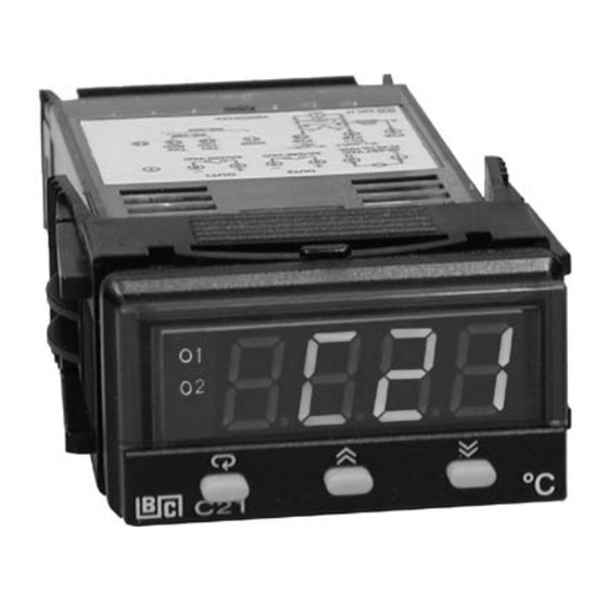
Figure 1.4 Display of Initial Stage...
1- 5 Menu Overview 1- 5 Menu Overview Setup menu*1 Setup menu*1 User menu *1 User menu *1 Calibration Mode Calibration Mode 5 sec. 6.2 sec. 7.4 sec. 2 sec. LOCK Value INPT ADLO Value UNIT ADHI Manual Manual 5 sec. RTDL Mode Mode...
1-6 Parameter Descriptions 1-6 Parameter Descriptions Parameter Default Parameter Description Range Notation Value 25.0 C Set point for output 1 Low: SP1L High :SP1H (77.0 F) Set point for output 2 when output 2 performs 10.0 C Low: -19999 High :45536 (18.0 F) alarm function or dwell timer...
Page 15
Parameter Default Range Parameter Description Notation Value Degree C unit Input unit selection Degree F unit UNIT Process unit No decimal point 1 decimal digit Decimal point selection 2 decimal digits 3 decimal digits -17.8 Input low sale value High: Low: -19999 45486...
Page 16
Parameter Default Range Parameter Description Notation Value : Display process value normally DISP Normal display selection : Display set point 1 value normally 500.0 C 10.0 C Proportional band value High: Low: 0 (900.0 F) (18.0 F) Integral time value High: Low: 3600 sec...
Page 17
Parameter Default Range Parameter Description Notation Value : No Ramp Function : Use unit/minute as Ramp function RAMP Ramp Rate selection : Use unit/hour as Ramp Rate 500.0 C Ramp rate High: Low: 0 (900.0 F) : Output 2 No Function : Dwell timer action : Deviation High Alarm : Deviation Low Alarm...
Page 18
Parameter Default Range Parameter Description Notation Value Output 2 hysteresis value when output 2 0.1 C High: 50.0 C O2HY Low: 0.1 performs alarm (90.0 F) (0.2 F) function Output 2 cycle time High: 90.0 sec. Low: 0.1 18.0 CYC2 Cooling proportional High: 300 % Low: 50...
Page 19
Parameter Default Range Parameter Description Notation Value : 7 data bits Data bit count of digital DATA communication : 8 data bits : Even parity Parity bit of digital : Odd parity PARI communication : No parity bit : One stop bit Stop bit count of digital STOP communication...
Page 20
Parameter Default Range Parameter Description Notation Value Select 2'nd parameter SEL2 Same as SEL1 for user menu Select 3'rd parameter SEL3 Same as SEL1 for user menu Select 4'th parameter SEL4 Same as SEL1 for user menu Select 5'th parameter SEL5 Same as SEL1 for user menu...
Chapter 2 Installation Chapter 2 Installation Dangerous voltages capable of causing death are sometimes Dangerous voltages capable of causing death are sometimes present in this instrument. Before installation or beginning any present in this instrument. Before installation or beginning any cleaning or troubleshooting procedures the power to all equipment cleaning or troubleshooting procedures the power to all equipment must be switched off and isolated.
2 - 3 Wiring Precautions 2 - 3 Wiring Precautions Before wiring, verify the label for correct model number and Before wiring, verify the label for correct model number and options. Switch off the power while checking. options. Switch off the power while checking. Care must be taken to ensure that maximum voltage rating Care must be taken to ensure that maximum voltage rating specified on the label are not exceeded.
Figure 2.2 Figure 2.2 Lead Termination for C91 Lead Termination for C91 2.0mm 0.08" max. Figure 2.3 Figure 2.3 Lead Termination for C21 Lead Termination for C21 4.5 ~7.0 mm 0.18" ~0.27" 90-250 VAC 2A/240 VAC 2A/240 VAC 47-63 Hz,10VA...
Page 25
E ,TX2 OP2, S-485 or etransmission E+,TX1 & " CAT. I I 50 C max. air ambient se copper conductors ( except on T/C input ) Figure 2.5 Figure 2.5 Rear Terminal Connection Rear Terminal Connection for C91 for C91 M0C911D...
2 - 4 Power Wiring 2 - 4 Power Wiring The controller is supplied to operate at 11-26 VAC / VDC or 90-250 The controller is supplied to operate at 11-26 VAC / VDC or 90-250 VAC. Check that the installation voltage corresponds with the power VAC.
This error is far greater than controller error and cannot be corrected on the sensor except by proper selection and replacement. on the sensor except by proper selection and replacement. 2-6 Sensor Input Wiring 2-6 Sensor Input Wiring C21 C91 TC+, V+ TC+, V+ PTB, mA+ PTB, mA+...
C21 C91 120V /240V 120V /240V Mains Supply Mains Supply Three Three Phase Phase Heater Heater Power Power No Fuse No Fuse Three Phase Three Phase Contactor Breaker Breaker Delta Delta Heater Heater Load Load Figure 2.10 Figure 2.10 Output 1 Relay or Triac (SSR) to Drive Contactor...
C21 C91 120V /240V 120V /240V Mains Supply Mains Supply Three Three Phase Phase Heater Heater Power Power No Fuse No Fuse Three Phase Three Phase Contactor Breaker Breaker Delta Delta Heater Heater Load Load Figure 2.15 Figure 2.15 Output 2 Relay or Triac (SSR) to Drive Contactor...
2-9 Data Communication 2-9 Data Communication RS-485 to RS-232 RS-485 to RS-232 C21 C91 network adaptor network adaptor SNA10A or SNA10A or SNA10B SNA10B RS-232 Twisted-Pair Wire Twisted-Pair Wire C21 C91 Max. 247 units can be linked Max. 247 units can be linked...
RS-232 9-pin 9-pin RS-232 RS-232 port port CC94-1 Figure 2.22 Figure 2.22 RS-232 Wiring RS-232 Wiring If you use a conventional 9-pin RS-232 cable instead of CC94-1, the cable If you use a conventional 9-pin RS-232 cable instead of CC94-1, the cable must be modified according to the following circuit diagram.
Chapter 3 Programming Chapter 3 Programming Press for 5 seconds and release to enter setup menu. Press to select the desired parameter. The display indicates the parameter symbol. Press to view or adjust the value of the selected parameter. 3-1 Lockout 3-1 Lockout There are four security levels can be selected by using LOCK parameter.
process value INHI Figure 3.1 Figure 3.1 Conversion Curve for Conversion Curve for Linear Type Process Value Linear Type Process Value INLO input signal S SL S SL Formula : PV = INLO + ( INHI INLO ) Formula : PV = INLO + ( INHI INLO ) Example : A 4-20 mA current loop pressure transducer with range Example : A 4-20 mA current loop pressure transducer with range 0 - 15 kg/cm is connected to input, then perform the...
Page 36
Heat Only ON-OFF Control : Select REVR for OUT1, Set PB to 0, Heat Only ON-OFF Control : Select REVR for OUT1, Set PB to 0, O1HY is used to adjust dead band for ON-OFF control, The output 1 O1HY is used to adjust dead band for ON-OFF control, The output 1 hysteresis ( O1HY ) is enabled in case of PB = 0 .
Page 37
then increase OFST 25 %, and vice versa. After adjusting OFST value, then increase OFST 25 %, and vice versa. After adjusting OFST value, the process value will be varied and eventually, coincide with set point. the process value will be varied and eventually, coincide with set point. Using the P control ( TI set to 0 ), the auto-tuning is disabled.
Page 38
You can use the auto-tuning auto-tuning program for the new process or directly set the appropriate values for PB, TI & TD according to the historical records for the repeated systems. If the control behavior is still inadequate, then use manual tuning manual tuning to improve the control.
Page 39
OUT2=DE.HI SV+SP2 SV+SP2-O2HY Time OUT2 Action Figure 3.3 Output 2 Deviation Figure 3.3 Output 2 Deviation Time High Alarm High Alarm SP2+O2HY Time OUT2 Action Time Figure 3.4 Output 2 Process Figure 3.4 Output 2 Process Low Alarm Low Alarm UM0C911A...
3-4 Alarm 3-4 Alarm The output 2 can be selected as alarm output. There are 6 types of alarm functions and one dwell timer can be selected, and four kinds of alarm modes ( ALMD ) are available for each alarm function. process alarm process alarm sets two absolute trigger levels.
A-D converter of the unit fails. 3-5 Configure Display 3-5 Configure Display C21 can be configured to display the process value by selecting PV for DISP or to display the set point value by selecting SP1 for DISP in the normal condition.
Example for C91: Example for C91: Set OUT2=PVLO, LOCK=NONE, SEL1=INPT, SEL2=UNIT, SEL3=DP , SEL4~SEL8=NONE, then the display scrolling for C91 becomes 3 - 6 Ramp 3 - 6 Ramp The ramping function is performed during power up as well as any The ramping function is performed during power up as well as any time the set point is changed.
3-7 Dwell Timer 3-7 Dwell Timer Output 2 can be configured as dwell timer by selecting TIMR for OUT2. As the dwell timer is configured, the parameter SP2 is used for dwell time adjustment. The dwell time is measured in minute ranging from 0.1 to 4553.6 minutes.
3 - 8 PV Shift 3 - 8 PV Shift In certain applications it is desirable to shift the controller display In certain applications it is desirable to shift the controller display value from its actual value. This can be easily accomplished by using value from its actual value.
3- 9 Digital Filter 3- 9 Digital Filter In certain application the process value is too unstable to be read. To improve this a programmable low pass filter incorporated in the controller can be used. This is a first order filter with time constant specified by FILT parameter .
3 -10 Failure Transfer 3 -10 Failure Transfer The controller will enter failure mode failure mode as one of the following conditions occurs: SBER SBER occurs due to the input sensor break or input current below 1mA if 4-20 mA is selected or input voltage below 0.25V if 1-5 V is selected .
C21) or AT indicator is lit (for C91). 5. Press for at least 5 seconds. The AT indicator ( for C91 ) or the display ( for C21 )will begin to flash and the auto-tuning procedure is beginning. NOTE :...
Procedures: The auto-tuning can be applied either as the process is warming up ( Cold Start ) or as the process has been in steady state ( Warm Start ). After the auto-tuning procedures are completed, the AT indicator will cease to flash and the unit revert to PID control by using its new PID values.
5 for 5 seconds then the MAN indicator (for C91) or the display (for C21) will seconds then the MAN indicator (for C91) or the display (for C21) will begin to flash. The controller now enters the manual control mode.
PB too low PB too low Perfect Set point Set point P action P action PB too high PB too high Time TI too high TI too high Set point Set point I action I action Perfect TI too low TI too low Time TD too low...
Section 2-9. 3 -15 PV Retransmission 3 -15 PV Retransmission C91 and C21 can output (retransmit) process value via its retransmission terminals RE+ and RE- provided that the retransmission option is ordered. A correct signal type should be selected for COMM parameter to meet the retransmission option installed.
Chapter 4 Applications Chapter 4 Applications 4 - 1 Heat Only Control with Dwell Timer 4 - 1 Heat Only Control with Dwell Timer An oven is designed to dry the products at 150 C for 30 minutes and then stay unpowered for another batch. A C91 equipped with dwell dwell timer...
4 - 2 Cool Only Control 4 - 2 Cool Only Control A C91 is used to control a refrigerator at temperature below 0 C. The temperature is lower than the ambient, a cooling action is required. Hence select DIRT for OUT1. Since output 1 is used to drive a magnetic contactor, O1TY selects RELY.
4 - 3 Heat-Cool Control 4 - 3 Heat-Cool Control An injection mold required to be controlled at 120 C to ensure a An injection mold required to be controlled at 120 C to ensure a consistent quality for the parts. An oil pipe is buried in the mold. Since consistent quality for the parts.
Page 55
The PID Heat-Cool is used for the above example. To achieve this set the following parameters in the Setup Menu: INPT=PT.DN INPT=PT.DN UNIT= C UNIT= C DP= 1-DP DP= 1-DP OUT1=REVR OUT1=REVR O1TY=RELY O1TY=RELY CYC1=18.0 (sec.) CYC1=18.0 (sec.) O1FT=BPLS O1FT=BPLS OUT2=COOL OUT2=COOL O2TY=4-20...
Chapter 5 Calibration Chapter 5 Calibration Do not proceed through this section unless there is a definite need to re-calibrate the controller. Otherwise, all previous calibration data will be lost. Do not attempt recalibration unless you have appropriate calibration equipment. If calibration data is lost, you will need to return the controller to your supplier who may charge you a service fee to re-calibrate the controller.
Page 57
Manual Calibration Procedures Manual Calibration Procedures Perform step 1 to enter calibration mode. Set the Lock parameter to the unlocked condition ( LOCK= Step 1. Step 1. NONE). Press and hold the scroll key until appears on the display, then release the scroll key. Press the scroll key for 2 seconds then release,the display will show and the unit enters calibration mode .
Step 4. Step 4. Press scroll key until the display shows . Send a 100 ohms signal to the RTD input terminals according to the connection shown below: 100 ohms Figure 5.1 RTD Calibration Figure 5.1 RTD Calibration Press scroll key for at least 5 seconds . The display will blink a moment, otherwise the calibration fails.
5520A 5520A Calibrator Calibrator K-TC Stay at least 20 minutes in still- Stay at least 20 minutes in still- air room air room room temperature 25 room temperature 25 Figure 5.2 Figure 5.2 Cold Junction Calibration Setup Cold Junction Calibration Setup The 5520A calibrator is configured as K type thermocouple output The 5520A calibrator is configured as K type thermocouple output with internal compensation.
Page 60
Perform step 1 stated above , then press scroll key until the display shows . Press scroll key for at least 5 seconds. The display will blink a moment and a new value is obtained. Otherwise , if the display didn't blink or if the obtained value is equal to -199.9 or 199.9, then the calibration fails.
Chapter 6 Specifications Chapter 6 Specifications Power 90 250 VAC, 47 63 Hz, 10VA, 5W maximum 90 250 VAC, 47 63 Hz, 10VA, 5W maximum 11 26 VAC / VDC, 11 26 VAC / VDC, SELV, Limited Energy, SELV, Limited Energy, 10VA, 5W maximum 10VA, 5W maximum Input...
Page 62
Characteristics: Input Input Accuracy Accuracy Type Range Impedance Impedance @ 25 C @ 25 C -120 C 1000 C -120 C 1000 C 2.2 M 2.2 M ( -184 F 1832 F ) ( -184 F 1832 F ) -200 C 1370 C -200 C 1370 C 2.2 M 2.2 M...
Page 63
Output 1 / Output 2 Output 1 / Output 2 Relay Rating : Relay Rating : 2A/240 VAC, life cycles 200,000 for 2A/240 VAC, life cycles 200,000 for resistive load resistive load Pulsed Voltage : Pulsed Voltage : Source Voltage 5V, Source Voltage 5V, current limiting resistance 66 current limiting resistance 66...
Page 64
DC Voltage Supply Characteristics ( Installed at Output 2 ) DC Voltage Supply Characteristics ( Installed at Output 2 ) Type Tolerance Max. Output Current Max. Output Current Ripple Voltage Ripple Voltage Isolation Barrier Isolation Barrier A1 V A1 V 0.2 Vp-p 0.2 Vp-p 20 V...
Page 65
Single 4-digit LED Display Single 4-digit LED Display Keypad : Keypad : 4 keys for C91, 3 keys for C21 4 keys for C91, 3 keys for C21 Programming Port : Programming Port : For automatic setup, calibration and testing...
Page 66
Moldings : Flame retardant polycarbonate Flame retardant polycarbonate Dimensions : Dimensions : C21-----50mm(W) X 26.5mm(H) X 110.5mm(D), C21-----50mm(W) X 26.5mm(H) X 110.5mm(D), 98 mm depth behind panel 98 mm depth behind panel C91-----48mm(W) X 48mm(H) X 94mm(D), C91-----48mm(W) X 48mm(H) X 94mm(D),...
Chapter 7 Modbus Communications Chapter 7 Modbus Communications This chapter specifies the Modbus Communications protocol as RS-232 or RS-485 interface module is installed. Only RTU mode is supported. Data is transmitted as eight-bit binary bytes with 1 start bit, 1 stop bit and optional parity checking (None, Even or Odd). Baud rate may be set to 2400, 4800, 9600, 14400, 19200, 28800 and 38400.
Page 68
Function 16: Preset Multiple Registers Function 16: Preset Multiple Registers Query ( from master ) Query Response ( from slave ) Response Slave address (0-255) Function code (16) Starting address of register Hi (0) Starting address of register Lo (0-79, 128-131) No.
7-2 Exception Responses 7-2 Exception Responses If the controller receives a message which contains a corrupted character (parity check error, framing error etc.), or if the CRC16 check fails, the controller ignores the message. However, if the controller receives a syntactically correct message which contains an illegal value, it will send an exception response, consisting of five bytes as follows: slave address +offset function code + exception code + CRC16 Hi +...
Low limit of SP1 SP1L High limit of SP1 SP1H PV shift value SHIF Filter time constant FILT 65535 Display form ( for C21 ) 65535 DISP P ( proportional ) band Integral time 65535 Derivative time 6553.5 Output 1 function...
Page 71
Register Scale Parameter Scale Parameter Notes High Address Notation Output 2 cycle time CYC2 6553.5 Cooling P band 65535 Heating-cooling dead band -1999.9 4553.6 Alarm function ALFN 65535 Retransmission high scale value REHI Alarm opertion mode 65535 ALMD Alarm hysteresis ALHY Alarm failure transfer 65535...
Page 72
H'0X00 = Alarm status is off H'010X = Calibration mode H'0x01 = Alarm status is on H'020X = Auto-tuning mode H'030X = Manual control mode The alarm status is shown in H'040X = Failure mode MV2 instead of MODE for models C21 and C91. UM0C911C...
Page 73
*3: The PROG Code is defined in the following table: Model No. BTC-9100 BTC-8100 BTC-4100 BTC-7100 PROG Code 6.XX 11.XX 12.XX 13.XX 33.XX 34.XX Where XX denotes the software version number. For example: PROG=34.18 means that the controller is C91 with software version *4: The scale high/low values are defined in the following table for SP1, INLO, INHI, SP1L, SP1H, SHIF, PV, SV, RELO and REHI: Non-linear...
For BTC-9100, BTC-8100, BTC-7100 and BTC-4100 Non-linear Linear input Linear input Linear input Linear input Conditions input DP = 0 DP = 1 DP = 2 DP = 3 -1999.9 -19999 -1999.9 -199.99 -19.999 Scale low Scale high 4553.6 45536 4553.6 455.36 45.536...
Page 75
4F 19 4E 83 4E 83 Addr. Func. Starting Addr. No. of words Bytes SP1=25.0 SP2=10.0 SP3=10.0 LOCK=0 INPT=1 UNIT=0 DP=1 INLO=-17.8 INHI=93.3 21 4E 00 02 00 SP1L=-17.8 SP1H=537.8 SHIF=0.0 FILT=2 DISP=0 PB=10.0 TI=100 TD=25.0 OUT1=0 O1TY=0 O1FT=0 O1HY=0.1 CYC1=18.0 OFST=25.0 RAMP=0 RR=0.0 OUT2=2 RELO=0.0 O2TY=0 O2FT=0...
Page 76
Example 2: Read PV, SV, MV1 and MV2. Example 2: Read PV, SV, MV1 and MV2. Send the following message to the controller via the COMM port or programming port: H'40 H'80 Addr. Func. Starting Addr. No. of words CRC16 Example 3: Perform Reset Function (same effect as pressing Example 3: Perform Reset Function (same effect as pressing key)
Table A.1 Error Codes and Corrective Actions Table A.1 Error Codes and Corrective Actions Display Error Error Description Corrective Action Symbol Code Illegal setup values been used: Check and correct setup values of Before COOL is used for OUT2, OUT2, PB, TI and OUT1. IF OUT2 DIRT ( cooling action ) has already is required for cooling control, the been used for OUT1, or PID mode...
WARRANTY Brainchild Electronic Co. is pleased to offer suggestions on the use of its various products. However, Brainchild makes no warranties or representations of any sort regarding the fitness for use, or the application of its products by the Purchaser. The selection, application or use of Brainchild products is the Purchaser's responsibility.
Page 79
BRAINCHILD Electronic Co., Ltd. BRAINCHILD Electronic Co., Ltd. No.209, Chung Yang Rd., Nan Kang Dist., No.209, Chung Yang Rd., Nan Kang Dist., Taipei, Taiwan, R.O.C. 115 Taipei, Taiwan, R.O.C. 115 Tel: 886-2-27861299 Tel: 886-2-27861299 Fax: 886-2-27861395 Fax: 886-2-27861395 web site: http://www.brainchild.com.tw...