
Subscribe to Our Youtube Channel
Related Manuals for Brainchild L91


Summary of Contents for Brainchild L91
- Page 1 User's Manual DIN EN ISO 9001 Certificate: 01 100 98505 APPROVED TEMPERATURE LIMIT CONTROLLER L91 UM0L911C BRAINCHILD...
- Page 2 Read Page 12 NOTE: It is strongly recommended that a process should incorporate a LIMIT CONTROL like L91 which will shut down the equipment at a preset process condition in order to preclude possible damage to products or system. Information in this user's manual is subject to change without notice.
-
Page 3: Table Of Contents
Contents Page No Page No Chapter 1 Overview 3-4 PV Shift 3-5 Digital Filter 1-1 General 1-2 Ordering Code 3-6 Process Alarms 1-3 Programming Port 3-7 RS-485 Communication 1-4 Keys and Display 3-8 Display Mode 3-9 Signal Conditioner DC 1-5 Menu Overview Power Supply 1-6 Limit Control Operation 3-10 Remote Reset... - Page 4 Figures & Tables Page No Figure 1-1 Programming Port Location Figure 1-2 Front Panel Display Figure 1-3 Power Up Sequence Figure 1-4 High Limit Operation Figure 1-5 Low Limit Operation Figure 1-6 High/Low Limit Operation Figure 2-1 Mounting Diagram Figure 2-2 Lead Termination Figure 2-3 Rear Terminal Connection Diagram Figure 2-4 Power Supply Connections Figure 2-5 Thermocouple Input Wiring...
-
Page 5: Chapter 1 Overview
The input signal is digitized by using a 18-bit A to D converter. Its fast sampling rate (5 times/second) allows the L91 to control fast process such as pressure and flow. Digital communication RS-485 is available as an additional option. -
Page 6: Ordering Code
CM96-3 = Isolated 4-20mA / 0-20mA Retransmission Module CM96-4 = Isolated 1-5V / 0-5V Retransmission Module CM96-5 = Isolated 0-10V Retransmission Module EI96-1 = Event Input Module CC91-2 = Programming port cable for L91 UM0L911C = L91 User's Manual UM0L911C... -
Page 7: Programming Port
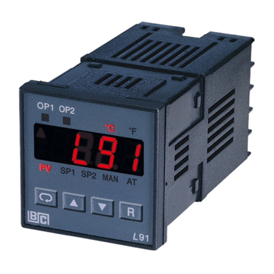
Power board Open the housing Figure 1-1 Programming Top view of L91 Port Location Note: The programming port is used for off-line setup and calibration procedures only. Don't attempt to make any connection to these jumpers when the unit is used for a normal control purpose. - Page 8 LF: Degree F indicator HSP1 LSP1 SP2 LOCK PV: Process value HSP1: High limit set point 1 RESET LSP1: Low limit set point 1 BRAINCHILD SP2: Set point 2 for output 2 LOCK: Lock status indicator Figure 1-2 Front Panel Display UM0L911C...
- Page 9 DISPLAY FORM Table 1-1 Display Form of Characters : These characters are displayed differently. How to display a 5-digit number : For a number with decimal point the display will be shifted one digit right: -199.99 will be displayed as -199.9, 4553.6 will be displayed as 4553 For a number without decimal point the display will be divided into two alternating phases: -19999 will be displayed as:...
- Page 10 If failure is detected in the A-D converter circuit, the display will show: POWER UP SEQUENCE LIMIT CONTROL All segments of display and indicators are left off for 0.5 second. RESET BRAINCHILD LIMIT CONTROL All segments of display and indicators are HSP1 LSP1 SP2 LOCK lit for 1 second.
- Page 11 LIMIT CONTROL Display the serial number ( 001~999 ) for 1 HSP1 LSP1 SP2 LOCK second. RESET BRAINCHILD LIMIT CONTROL HSP1 LSP1 SP2 LOCK RESET Display the hours used for 2 seconds. The BRAINCHILD left diagram shows that the unit has been used for 23456.7 hours since production.
-
Page 12: Menu Overview
1-5 Menu Overview Setup Mode Press for 4 sec. Input type INPT PV Value Process UNIT Process unit value or SAFE Display resolution RESO Low scale value for linear IN.LO input High limit High scale value for linear IN.HI input HSP1 Value setpoint 1 SHIF... -
Page 13: Limit Control Operation
Note 1. The flow charts show a complete listing of parameters. For actual application the number of available parameters is dependent on the setup conditions, and should be less than that shown in the flow charts. Note 2. Press key for 4 seconds to enable up/down key RESET function, and the LOCK indicator will be extinguished. - Page 14 LOW LIMIT OPERATION If Lo. is selected for OUT1, the unit will perform low limit control. When power is applied the OUT1 relay is de-energized. After 6.5 seconds self-test period, if the process is above the low limit set point (LSP1), the output 1 relay will be energized and OP1 indicator will go off.
- Page 15 HIGH/LOW LIMIT OPERATION If Hi.Lo is selected for OUT1, the unit will perform high/low limit control. When power is applied the OUT1 relay is de-energized. After 6.5 seconds self-test period, if the process is below the high limit set point (HSP1) and above the low limit set point (LSP1), the output 1 relay will be energized and OP1 indicator will go off.
-
Page 16: Parameter Descriptions
1-7 Parameter Descriptions Parameter Parameter Default Range Notation Description Value Low: HSP .L 100.0 BC High Limit Set point 1 HSP1 High: HSP .H (212.0 BF) Low: LSP .L 0 BC Low Limit Set point 1 LSP1 High: LSP .H (32.0 BF) Low: -19999 Set point 2 Value for... - Page 17 Parameter Parameter Default Range Notation Description Value : 4~20 mA linear current : 0~20 mA linear current : 0~60 mV linear voltage : 0~1 V Input Type Selection INPT ( 0 ) linear voltage : 0~5 V linear voltage : 1~5 V linear voltage : 0~10V linear voltage...
- Page 18 Parameter Parameter Default Range Notation Description Value High Scale Value for Low: IN.LO 100.0 IN.HI Linear Input High: 45536 Low: -200.0 BC PV Shift ( offset ) (-360.0 BF) SHIF High: 200.0 BC Value (360.0 BF) : 0 second time constant : 0.2 second time constant : 0.5 second...
- Page 19 Parameter Parameter Default Range Notation Description Value Low: 0.1 Output 1 Hysteresis O1.HY High: 10.0 BC (18.0 BF) Value Low: -19999 0 BC HSP .L Lower Limit of HSP1 High: HSP .H (32.0 BF) Low: HSP .L 1000.0 BC HSP .H Upper Limit of HSP1 High: 45536 (1832.0 BF)
- Page 20 Parameter Parameter Default Range Notation Description Value : 1.2 Kbits/s baud rate : 2.4 Kbits/s baud rate : 4.8 Kbits/s baud rate : 9.6 Kbits/s Baud Rate of Digital baud rate BAUD COMM : 14.4 Kbits/s baud rate : 19.2 Kbits/s baud rate : 28.8 Kbits/s baud rate...
- Page 21 Parameter Parameter Default Range Notation Description Value : Normal alarm action AL.MD Alarm mode : Latching alarm action Low: 0.1 Alarm hysteresis High: 10 BC AL.HY value (18.0 BF ) : Alarm output goes off as unit fails AL.FT Alarm failure transfer : Alarm output goes on as unit fails...
-
Page 22: Chapter 2 Installation
Chapter 2 Installation Dangerous voltages capable of causing death are sometimes present in this instrument. Before installation or beginning any troubleshooting procedures the power to all equipment must be switched off and isolated. Units suspected of being faulty must be disconnected and removed to a properly equipped workshop for testing and repair. -
Page 23: Wiring Precautions
Install both mounting clamps and insert the housing into panel cutout. +0.5 Panel cutout +0.5 Panel 86 mm 94 mm Figure 2-1 Mounting Diagram 2 - 3 Wiring Precautions Before wiring, verify the label for correct model number and options. Switch off the power when checking. Care must be taken to ensure that maximum voltage rating specified on the label are not exceeded. - Page 24 Unused control terminals should not be used as jumper points as they may be internally connected, causing damage to the unit. Verify that the ratings of the output devices and the inputs as specified in Chapter 6 are not exceeded. Electric power in industrial environments contains a certain amount of noise in the form of transient voltage and spikes.
-
Page 25: Power Wiring
2-4 Power Wiring The unit is supplied to operate at 11-26 VAC / VDC or 90- 264VAC.Check that the installation voltage corresponds with the power rating indicated on the product label before connecting power to the unit. Fuse 264 VAC or 26 VAC / VDC Figure 2-4 Power Supply Connections... -
Page 26: Thermocouple Input Wiring
In a liquid process, addition of a stirrer will help to eliminate thermal lag. Since the thermocouple is basically a point measuring device, placing more than one thermocouple in parallel will provide an average temperature readout and produce better results in most air heated processes. -
Page 27: Rtd Input Wiring
Figure 2.5 Thermocouple Input Wiring 2-7 RTD Input Wiring RTD connection are shown in Figure 2-6, with the compensating lead connected to terminal 4. For two-wire RTD inputs, terminals 4 and 5 should be linked. The three-wire RTD offers the capability of lead resistance compensation provided that the three leads are of same gauge and equal length. -
Page 28: Linear Dc Input Wiring
2-8 Linear DC Input Wiring DC linear voltage and linear current connections are shown in Figure 2-7 and Figure 2-8 . 0~60mV, 0~1V, 0~5V, 1~5V, 0~10V Figure 2.7 Linear Voltage Input Wiring 0~20mA or 4~20mA Figure 2.8 Linear Current Input Wiring UM0L911C... -
Page 29: Event Input Wiring
2-9 Event Input wiring Open Collector Switch Input Input Figure 2-9 Event Input Wiring The event input can accept a switch signal as well as an open collector signal. The event input function (EIFN) is activated as the switch is closed or an open collector (or a logic signal ) is pulled down. -
Page 30: Output 1 Wiring
2-10 Output 1 Wiring Figure 2-10 Output 1 Wiring Max. 2A Resistive Load 120V/240V Mains Supply To Controller Relay or Triac Output Direct Drive Output 120V /240V Mains Supply To Controller Output Three Phase Heater Power Three Contactor Phase Delta Heater Relay or Triac (SSR) Load... -
Page 31: Output 2 Wiring
2-11 Output 2 Wiring Max. 2A Resistive LOAD 120V/240V Supply Relay or Triac Output LOAD 120V/240V Supply Pulsed Voltage to Drive SSR Sensor Transmitter DC Power Supply Output Figure 2-11 Output 2 Wiring UM0L911C... -
Page 32: Rs-485
2-12 RS-485 RS-485 to RS-232 network adaptor SNA10A RS-485 RS-232 Twisted-Pair Wire Max. 247 units can be linked Terminating Resistor 220 ohms/0.5W Figure 2-12 RS-485 Wiring UM0L911C... -
Page 33: Chapter 3 Programming
Chapter 3 Programming 3-1 Process Input Press for 4 seconds to enter setup mode. Press to select parameter. The display will indicate the parameter symbol and the value ( or selection ) for that parameter. INPT: Selects the sensor type and signal type for the process input. UNIT: Selects the process unit. -
Page 34: Limit Control
Formula: PV = IN.LO + ( IN.HI IN.LO ) S-SL SH-SL Example: a 4-20 mA current loop pressure transducer with range 0 - 15 kg/cm , is connected to input, then perform the following setup: INPT = 4-20 mA IN.LO = 0.0 UNIT = PU IN.HI = 15.0 RESO = 1-DP... -
Page 35: Pv Shift
In certain applications the process value is too unstable to be read. To Improve this a programmable low pass filter incorporated in the L91 can be used. This is a first order filter with time constant specified by FILT parameter which is contained in setup menu. -
Page 36: Process Alarms
3-6 Process Alarms The output 2 will perform process alarm function by selecting ALM for OUT2 and PV.H.A or PV.L.A for AL.FN. If PV.H.A is selected the alarm will perform process high alarm. If PV.L.A is selected the alarm will perform process low alarm. The process alarm sets an absolute trigger level. -
Page 37: Communication
Examples: Figure 3.3 Process proceeds Normal Process Alarm Figure 3.4 SP2 = 200 AL.HY = 10.0 Latching Process Alarm AL.MD = LTCH AL.FN = PV.H.A Process proceeds 3-7 RS-485 Communication Using a PC for data communication is the most economic way. The signal is transmitted and received through the PC communication Port (generally RS-232). -
Page 38: Display Mode
Select COMM for OUT2 in setup menu, the output 2 will perform RS-485 interface with Modbus RTU Mode protocol. Setup 1. Select COMM for OUT2 2. Set an unequal address (ADDR) for those units which are connected to the same port. 3. - Page 39 Two wire Transmitter OUT2 = DC Power Supply Figure 3-5 4-20mA DC Power Supply Application Three wire Transmitter or sensor V or mA Bridge Type Sensor Caution: Don't use the DC power supply beyond its rating current to avoid damage. Purchase a correct voltage to suit your external devices.
-
Page 40: Remote Reset
3-10 Remote Reset If EIFN is selected for OUT2 and REST is selected for EIFN, terminals 1 & 2 will act as remote reset input. Pressing remote reset button will perform the same function as pressing the RESET key. Refer to section 1-4 for RESET key function. -
Page 41: Limit Annunciator
3-12 Limit Annunciator If L_AN (Limit annunciator) is selected for OUT2, the output 2 will act as a Limit Annunciator. If the limit is or has been reached and the RESET key (or remote reset contacts)has not been pressed since the limit was reached, then the limit annunciator output will be energized and the OP2 indicator will be lit and remain unchanged until the RESET key or remote reset input is applied. -
Page 42: Chapter 4 Applications
An oven uses a single phase heater to heat the process. A single loop temperature control C91 is used to regulate the temperature. A limit control L91 is used to protect the process from being over heated. The wiring diagram is shown below. -
Page 43: Chapter 5 Calibration
Chapter 5 Calibration Do not proceed through this section unless there is a definite need to re-calibrate the controller. Otherwise, all previous calibration data will be lost. Do not attempt re-calibration unless you have appropriate calibration equipment. If calibration data is lost, you will need to return the unit to your supplier who may change you a service fee to re-calibrate the unit. - Page 44 Figure 5-1 Flow Chart for Manual Normal Mode Calibraton 4 seconds RESET Setup Mode 4 seconds RESET Step 1 4 seconds RESET Step 2 4 seconds RESET Step 3 CJTL 4 seconds RESET Step 4 4 seconds RESET Step 5 4 seconds RESET Step 6...
- Page 45 Step 2: Calibrate Gain of A to D converter. Send a span signal to terminal 4 and 5 with correct polarity. The span signal is 60 mV for thermocouple input, 1V for 0-1V input, 10V for 0-10V input and 20mA for 0-20 mA input. Press for at least 4 seconds.
- Page 46 Step 4: Calibrate gain cold junction Setup the equipment same as step 3. The unit under calibration is power in a still-air room with temperature 50A3 BC. Stay at least 20 minutes for warming up. The calibrator source is set at 0.00 BC with internal compensation mode. Press for at least 4 seconds.
- Page 47 Input Function T/C, RTD, 0~60mV 1.8K 0 ~ 1 V 61.9K 3.92K 0 ~ 5V, 1 ~ 5V 324K 3.92K 0 ~ 10 V 649K 3.92K 0~20mA, 4~20mA 3.01W 2. Perform Step 1 to calibrate the linear input zero. 3. Perform Step 2 but send a span signal to the input terminals instead of 60mV.
-
Page 48: Chapter 6 Specifications
Chapter 6 Specifications Power 90-264 VAC, 49-63 Hz, 10 VA, 5W maximum 11-26 VAC/VDC, 10 VA, 5W maximum Input Resolution: 18 bits Sampling: 5 times/second Maximum Rating: -2 VDC minimum, 12 VDC maximum (1 minute for mA input) Temperature Effect: A1.5 uV / BC Sensor Lead Resistance Effect: T/C: 0.2 uV/ohm... - Page 49 Characteristics: Input Accuracy Type Range Impedance @ 25 C -120 C 1000 C A2 LC 2.2 M ( -184 F 1832 F ) -200 C 1370 C A2 LC 2.2 M ( -328 F 2498 F ) -250 C 400 C A2 LC 2.2 M ( -418 F 752 F )
- Page 50 Event Input Logic Low: -10V minimum, 0.8V maximum. Logic High: 2V minimum, 10V maximum. Functions: Remote reset, remote lockout. Output 1 / Output 2 Relay Rating: 2A/240 VAC, life cycles 200,000 for resistive load. Pulsed Voltage: Source Voltage 5V, current limiting resistance 66 ohms.
- Page 51 User Interface 4-digit LED Displays: 0.4" (10mm), keypad: 4 keys Programming Port: For automatic setup, calibration and testing. Communication Port: Connection to PC for supervisory control. Limit Control: High Limit, Low limit and High/Low Limit programmable Digital Filter Function: First order Time Constant: 0, 0.2, 0.5, 1, 2, 5, 10, 20, 30, 60 seconds programmable...
-
Page 52: Modbus Communications
Chapter 7 Modbus Communications This chapter specifies the Modbus Communications protocol as RS-232 or RS-485 interface module is installed. Only RTU mode is supported. Data is transmitted as eight-bit binary bytes with 1 start bit, 1 stop bit and optional parity checking (None, Even or Odd). Baud rate may be set to 300, 600, 1200, 2400, 4800, 9600, 14400, 19200, 28800 and 38400. - Page 53 Function 16: Preset Multiple Registers Query ( from master ) Response ( from slave ) Slave address (0-255) Function code (16) Starting address of register Hi (0) Starting address of register Lo (0-61, 128-143) No. of words Hi (0) No. of words Lo (1-18) CRC16 Hi Byte count (2-36)
- Page 54 7-3 Parameter Modbus Register Mapping Table Register Parameter Scale Scale Parameter Notes Address Notation High Reserved High limit set point 1 HSP1 Low limit set point 1 LSP1 Set point 2 value for output 2 Reserved Reserved Historical max. value of PV PV.HI Historical min.
- Page 55 Register Parameter Scale Scale Parameter Notes Address Notation High Lower limit of LSP1 LSP .L Upper limit of LSP1 LSP .H Reserved Reserved Analog output function AOFN 65535 Output 2 function 65535 OUT2 Reserved Reserved Reserved Reserved Address ADDR 65535 Baud rate BAUD 65535...
- Page 56 *3: The PROG code is defined by 2.XX, where XX denotes the software version number. For example : PROG=2.17 means the product is L91 with software version 17. *4: The least significant bit (LSB) of ALM shows the status of output 1.
- Page 57 7-4 Data Conversion The word data are regarded as unsigned ( positive ) data in the Modbus message. However, the actual value of the parameter may be negative value with decimal point. The high/low scale values for each parameter are used for the purpose of such conversion. Let M = Value of Modbus message A = Actual value of the parameter SL = Scale low value of the parameter...
- Page 58 (1) Unlock the controller Reg. Addr. Addr. Func. CMND=26668 CRC16 (2) Preset the first group of the parameters Addr. Func. Starting Addr. No. of words Bytes INPT=1 UNIT=0 RESO=1 IN.LO=0 IN.HI=100.0 SHIF=0.0 FILT=2 CRC16 (3) Preset the second group of the parameters Func.
- Page 59 Example 2: Read the process value (PV) Send the following message to the controller via the COMM port or the programming port : Query Starting Addr. Addr. Func. No. of words CRC16 Example 3: Perform reset function ( same effect as pressing key ): RESET Query...
-
Page 60: Error Codes
Table A.1 Error Codes and Corrective Actions Display Error Error Description Corrective Action Symbol Code Communication error: bad function Correct the communication code software to meet the protocol requirements. Don't issue an over-range Communication error: register address out of range register address to the slave. - Page 61 WARRANTY Brainchild Electronic Co., Ltd. is pleased to offer suggestions on the use of its various products. However, Brainchild makes no warranties or representations of any sort regarding the fitness for use, or the application of its products by the Purchaser.
- Page 62 Electronic Co., Ltd. No.209, Chung Yang Rd., Nan Kang Dist., Taipei, Taiwan, R.O.C. 115 Tel: 886-2-27861299 Fax: 886-2-27861395 website: www.brainchildtw.com...
Need help?
Do you have a question about the L91 and is the answer not in the manual?
Questions and answers