
Related Manuals for mundoclima MUCO-H6T


Summary of Contents for mundoclima MUCO-H6T
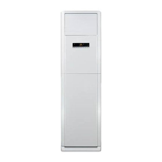
- Page 1 FLOOR STANDING Service manual MUCO-H6T CL20390 to CL20391 English www.mundoclima.com...
-
Page 2: Table Of Contents
Service Manual Table of Contents Part Ⅰ : Technical Information ................4 1. Summary ......................... 4 2. Specifications ......................5 2.1 Specification Sheet ......................5 2.2 Capacity Curve in Different Outdoor Temperature .............. 9 2.3 Cooling and Heating Data Sheet in Rated Frequency ............9 3. - Page 3 Service Manual 9. Maintenance ......................44 9.1 Error Code ........................44 9.2 Procedure of Troubleshooting ..................46 9.3 Maintenance Method for Normal Malfunction ..............50 10. Exploded View and Parts List ..............52 10.1 Indoor Unit ........................52 10.2 Outdoor Unit ........................55 11.
-
Page 4: Part Ⅰ : Technical Information
Service Manual Part Ⅰ : Technical Information 1. Summary Outdoor Unit: Indoor Unit: Remote Controller: MUCO-48-H6T YB1F2(XFAN) MUCO-60-H6T MUCO-48-H6T (CL96462) AUTO HEALTH X-FAN HUMIDITY FILTER TURBO HOUR ON/OFF ON/OFF MODE X-FAN TEMP TIMER TURBO SLEEP LIGHT MUCO-60-H6T... -
Page 5: Specifications
Service Manual 2. Specifications 2.1 Specification Sheet Model MUCO-48-H6T Product Code CL20390 Rated Voltage 380-415 Power Rated Frequency Supply Phases Power Supply Mode Outdoor Cooling Capacity 12310 Heating Capacity 12310 Cooling Power Input 4900 Heating Power Input 4400 Cooling Power Current Heating Power Current Rated Input 6400... - Page 6 Service Manual Model of Outdoor Unit MUCO-48-H6T Outdoor Unit Product Code UE20390 Compressor Manufacturer/Trademark Dalian SANYO Compressor Co.;Ltd. Compressor Model C-SBP160H38C Compressor Oil FV68S Compressor Type Scroll L.R.A. Compressor RLA 7.58 Compressor Power Input 4300 Overload Protector 37HM536-15 Throttling Method Capillary Operation Temp 16~30...
- Page 7 Service Manual Model MUCO-60-H6T Product Code CL20391 Rated Voltage 380-415 Power Rated Frequency Supply Phases Power Supply Mode Outdoor Cooling Capacity 15000 Heating Capacity 17500 Cooling Power Input 6000 Heating Power Input 5850 Cooling Power Current 9.61 Heating Power Current Rated Input 8000(10500) Rated Current...
- Page 8 Service Manual Model of Outdoor Unit MUCO-60-H6T Outdoor Unit Product Code UE20391 Compressor Manufacturer/Trademark Dalian SANYO Compressor Co.; Ltd. Compressor Model C-SBP185H38A Compressor Oil FV68S Compressor Type Scroll L.R.A. Compressor RLA 9.31 Compressor Power Input 5200 Overload Protector UP18RA052-550 Throttling Method Capillary Operation Temp 16~30...
-
Page 9: Capacity Curve In Different Outdoor Temperature
Service Manual 2.2 Capacity Curve in Different Outdoor Temperature Cooling: Heating: ConditionIndoor: DB20 ; °C Indoor air flow: Super High Pipe ConditionIndoor: DB27 ,WB19 ; °C °C length: 5m. Indoor air flow: Super High Pipe length: 5m. 32 33 34 35 36 37 38 39 40 41 42 43 44 45 46 Outdoor temp.( ) °C Outdoor Temp.(... -
Page 10: Outline Dimension Diagram
Service Manual 3. Outline Dimension Diagram 3.1 Indoor Unit MUCO-48-H6T MUCO-60-H6T Unit:mm... -
Page 11: Outdoor Unit
Service Manual 3.2 Outdoor Unit MUCO-48-H6T 1018 Unit:mm MUCO-60-H6T 1032 Unit:mm... -
Page 12: Refrigerant System Diagram
Service Manual 4. Refrigerant System Diagram Outdoor unit Indoor unit Gas pipe side Valve 4-Way valve Di s charge Heat Suction Accumlator exchanger Compressor (evaporator) Heat exchanger Liquid pipe (condenser) side Valve Capillary Strainer Strainer COOLING HEATING Connection pipe specification: Liquid pipe:1/2"... -
Page 13: Electrical Part
Service Manual 5. Electrical Part 5.1 Wiring Diagram ● Instruction Symbol Symbol Color Symbol Symbol Color Symbol Name White Green OVERLOAD Yellow Brown COMP Compressor Blue Grounding wire YEGN Yellow/Green Black CBB65 Violet Orange CBB61 Indoor Unit ● MUCO-48-H6T 600007000276... - Page 14 Service Manual MUCO-60-H6T 600007000276...
- Page 15 side Valve Capillary Strainer Service Manual ● Outdoor Unit MUCO-48-H6T 600007000274 These wiring diagrams are subject to change without notice; please refer to the one supplied with the unit.
- Page 16 Service Manual MUCO-60-H6T 600007000361 These wiring diagrams are subject to change without notice; please refer to the one supplied with the unit.
-
Page 17: Pcb Printed Diagram
Service Manual 5.2 PCB Printed Diagram MUCO-48-H6T ● Top view Name Output terminal 2 of transformer Output terminal 1 of transformer Terminal of high pressure switch Terminal of low pressure switch Input terminal of transformer Fuse Terminal of live wire Control terminal of compressor Control terminal of 4-way valve Control terminal of electric... - Page 18 Service Manual MUCO-60-H6T ● Top view Name Output terminal 2 of transformer Output terminal 1 of transformer Terminal of high pressure switch Terminal of low pressure switch Input terminal of transformer Fuse Terminal of live wire Control terminal of compressor Control terminal of 4-way valve Control terminal of electric heating belt (only for the model...
-
Page 19: Function And Control
Service Manual 6. Function and Control 6.1 Instructions of Control Buttons on Indoor Panel Model:GVA48AH-M3NNA5C E-HEATER Speed ON/OFF Function AMB. Mode ON/OFF Button ON/OFF Button Under the situation without setting Press this button, to turn on the unit. buttons, the function, press When unit is turned on, the original setting like Timer, Sleep function will the setting temperature goes up... - Page 20 Service Manual E-HEATER Function AMB. Speed Mode ON/OFF Speed Buttons (Continued) Speed Button After switch-on at first time, if without Press this button, the speed can any button input:1. consecutively press shift in the circulation among of twice of buttons in 20 seconds and →...
- Page 21 Service Manual E-HEATER ON/OFF AMB. Speed Mode Function AMB. AMB. AMB.Buttons (Continued) AMB. Buttons (Continued) The modes of living room, restaurant, Under the modes of living room, conference/office can only be called restaurant, conference/office,The out by pressing buttons of air con- setting temperature, speed, blowing ditioner panel.
- Page 22 Service Manual E-HEATER AMB. Mode Speed Function ON/OFF Swing Status of swing Display status of swing. Setting Swing Display setting temperature. Status of swing Display status of swing. Room temperature Indicate temperature of indoor BLOW circumstances. BLOW Function Supper strong When the typeface light is on, it When the typeface light is on, it indicates setting the BLOW function.
-
Page 23: Remote Controller Introduction
Service Manual 6.2 Remote Controller Introduction Buttons on Remote Controller ON/OFF Button AUTO HEALTH X-FAN MODE Button HUMIDITY FILTER +/- Button TURBO HOUR FAN Button ON/OFF Button Button ON/OFF MODE HEALTH SAVE Button X-FAN Button TEMP Button TIMER Button X-FAN TEMP TIMER TURBO Button... - Page 24 Service Manual AUTO COOL DRY HEAT high speed. Auto no display (horizontal louvers stops at current position) Under unit off status, press “+” button and button simultaneously to switch between simple swing setting and fixed-angle swing setting. During switching the two swing settings, icon will blink for 2s.
- Page 25 Service Manual no display (horizontal louvers (swing angle is stops at current position) displayed dynamically) (swing angle is displayed dynamically) Under unit off status, press “+” button and button simultaneously to switch between simple swing setting and fixed-angle swing setting. During switching the two swing settings, icon will blink for 2s.
-
Page 26: Function Introduction For Combination Buttons
Service Manual At OFF status, press this button once can set TIMER ON. Please refer to TIMER off for detailed operation. ● Cancel TIMER ON: Press “TIMER” button again under TIMER ON status. Note: Time setting range: 0.5-24 hours. ● Time interval between two operations can’t exceed 5s. -
Page 27: Introduction Of Each Mode Function
Service Manual 6.3 Introduction of Each Mode Function 1. Running Mode 1. cooling; 2. dry; 3. fan; 4: heating; 5. AUTO; 6. others (Freon recovery mode). Temperature Para meter 1. Indoor ambient temperature Tamb. (adopt 15K temperature sensor, external connect 15K partial resistance); 2. - Page 28 Service Manual ( 3 ) Heating Mode ( this mode is not available for c ooling only un it) 1. Working condition and process for heating When Tamb. Tpreset-1 , the unit will run in heating mode. Meanwhile, compressor and outdoor fan will start running. Indoor fan may be start running after delayed for a period of time to prevent blowing out cold air.
- Page 29 Service Manual Freon Recovery Mode That’s the recovery operation method for refrigerant: After the A/C is energized for the first time, set the A/C at FAN mode, low fan speed by remote controller and the indoo r temperature is set as 20 ; Meanwhile, indoor fan will start running. Press the light button on remote controller for twice successively within 5s;...
- Page 30 Service Manual When turning on the unit each time, the swing blade must be open to angle 5 (mini position), and then compressor, fan etc. can run. When switching on controller or turning off the unit each time, the swing blade must be at OFF status. 4.
- Page 31 Service Manual 2. When compressor is stopped, if it’s detected that the low pressure switch is broken for 30s successively, the complete unit will stop running. Meanwhile, E3 will be displayed and the unit can’t resume running automatically. Only after restarting up the unit and the low pressure switch is resumed, the unit can resume sunning.
- Page 32 Service Manual 1. ON/OFF button Controller is turned on/off by pressing this button. After each pressing of this button, the on/off status will be switched for once. 2. Mode button After pressing this button, it will be selected and displayed as below: Auto cooling heating...
- Page 33 Service Manual Setting: default to display the setting temperature at ON status, default to display the setting temperature at off status Room temperature: default to display room temperature at on status, default to display to room temperature at off status. (3) After pressing ▲...
- Page 34 Service Manual Blow: when setting blow function, the icon and character will blink; when this function is selected, the icon and character will be displayed. If the blow function hasn’t been selected, the icon and character won’t be displayed. During the time of blow, only the icon and character are displayed, others won’t be displayed.
-
Page 35: Part Ⅱ : Installation And Maintenance
Service Manual Part Ⅱ : Installation and Maintenance 7. Notes for Installation and Maintenance 10. If the power cord or connection wire is not long enough, Safety Precautions: please get the specialized power cord or connection wire from the manufacture or distributor. Prohibit prolong the wire by Important! yourself. - Page 36 Service Manual Main Tools for Installation and Maintenance 1. Measuring tape 2. Screw driver 3. Impact drill, drill head, electric drill 4. Electroprobe 5. Universal meter 6. Torque wrench, open-end wrench, inner hexagon spanner 7. Electronic leakage detector 8. Vacuum pump 9.
-
Page 37: Installation
Service Manual 8. Installation 8.1 Installation Dimension Diagram Away from wall (30cm at least for piping side) Away from obstacles Away from wall (30cm at least for piping side) Away from back side... -
Page 38: Installation Procedures
Service Manual 8.2 Installation Procedures Start installation Preparation before installation Read the requirements select installation Prepare tools for electric connection location Select indoor unit Select outdoor unit installation location installation location Install the support of outdoor unit Drill wall holes (select it according to the actual situation) Connect pipes of indoor Fix outdoor unit... -
Page 39: Installation Parts-Checking
Service Manual 8.5 Electric Connection Requirement 8.3 Installation Parts-Checking Safety precaution: Name Name 1. Must follow the electric safety regulations when installing the Indoor unit Sealing gum unit. Outdoor unit Wrapping tape 2. If the supply cord is damaged, it must be replaced by the Support of outdoor Connection pipe manufacturer or its... - Page 40 Service Manual Note: Refer to the following table for wrench moment of force: 1.Pay attention to dust prevention and take relevant safety measures when opening the hole. Hex nut diameter(mm) Tightening torque(N m) 2.The plastic expansion particles are not provided and Φ6(1/4") 15~20 should be bought locally.
-
Page 41: Installation Of Outdoor Unit
yellow- brown black vioet blue green Service Manual Outdoor unit connection drain hose connection pipe band Note: the wiring connection is for reference only, please refer to the actual one. indoor power cord Fig.15 Note: 1.The power cord and control wire can't be crossed or winding. 2.The drain hose should be bound at the bottom. - Page 42 Service Manual Step five: connect outdoor electric wire 1.Remove the wire clip; connect the power connection wire and signal control wire (only for cooling and heating unit) to the wiring terminal according to the color; fix the power connection wire with screws.(As show in Fig.22) Fig.17 yellow- blue...
-
Page 43: Vacuum Pumping And Leak Detection
Service Manual Note: Leakage Detection 1.The through-wall height of drain hose shouldn't be higher 1. With leakage detector than the outlet pipe hole of indoor unit.(As show in Fig.25) Check if there is leakage with leakage detector. 2. Slant the drain hose slightly downwards. The drain hose 2.With soap water: can't be curved, raised and fluctuant, etc. -
Page 44: Maintenance
Service Manual 9. Maintenance 9.1 Error Code Display Method of Indoor Malfunction A/C Status Possible Causes Maintenance measures Unit Name Nixie tube display 1. The mainboard and the display board are not connected well; 2. The OVC terminal on mainboard is not connected well with the high pressure switch on the complete unit;... - Page 45 Service Manual 1. Unstable supply voltage. Normal fluctuation shall be within 10% of the rated voltage on the nameplate; 2. Supply voltage is too low and load is too high; 3. Measure the current of live wire on mainboard. If the current isn’t higher than the overcurrent protection value, please During cooling and drying check the mainboard;...
-
Page 46: Procedure Of Troubleshooting
Service Manual 9.2 Procedure of Troubleshooting 1. High pressure protection (E1) Start Are the display board and mainboard Connect the display board with the mainboard well Malfunction is eliminated. connected tightly? Are the OVC terminal on the mainboard Connect the OVC terminal on the main board with the high Malfunction is eliminated. - Page 47 Service Manual 2. Compressor low pressure protection (E3) Start Is the terminal of low Reconnect it firmly to make pressure switch is properly connected? sure it is properly contacted Malfunction is eliminated Is the system pressure higher Charge refrigerant according than the operation pressure value of to the system requirement low pressure switch?
- Page 48 Service Manual 3. High discharge temperature protection of compressor (E4) Check the wiring and fan capacitor; replace motor mainboard...
- Page 49 Service Manual 4. Malfunction of Overcurrent Protection (E5) Troubleshooting for E5 malfunction Is the supply voltage unstable Normal fluctuation is within 10 % of the rated Malfunction is with big fluctuation? voltage on the nameplate eliminated Is the supply voltage too low Malfunction is Malfunction is Adjust the supply voltage to maintain it within...
-
Page 50: Maintenance Method For Normal Malfunction
Service Manual 9.3 Maintenance Method for Normal Malfunction 1. Air Conditioner Can't be Started Up Possible Causes Discriminating Method (Air conditioner Status) Troubleshooting Confirm whether it's due to power failure. If yes, No power supply, or poor After energization, operation indicator isn’t bright wait for power recovery. - Page 51 Service Manual 4. ODU Fan Motor Can't Operate Possible causes Discriminating method (air conditioner status) Troubleshooting Connect wires according to wiring diagram to Wrong wire connection, or poor Check the wiring status according to circuit make sure all wiring terminals are connected connection diagram firmly...
-
Page 52: Exploded View And Parts List
Service Manual 10. Exploded View and Parts List 10.1 Indoor Unit MUCO-48-H6T MUCO-60-H6T 12 13 The component picture is only for reference; please refer to the actual product. - Page 53 Service Manual Part Code Description MUCO-48-H6T Product Code UI20390 Rear Plate Assy 01304500 Left Side Plate Sub-Assy 0130451901 Right Side Plate Sub-Assy 0130451801 Top Cover Sub-Assy 22244152 Breakwater Sub-Assy 01364154P Evaporator Assy 0100427201 Capillary Sub-assy (Heating) 03004012 Ambient Temperature Sensor 3900019003 Crank 73014023...
- Page 54 Service Manual Part Code Description MUCO-60-H6T Product Code UI20391 Rear Plate Assy 01304500 Left Side Plate Sub-Assy 0130451901 Right Side Plate Sub-Assy 0130451801 Top Cover Sub-Assy 22244152 Breakwater Sub-Assy 01364503P Evaporator Assy 011001000168 Capillary Sub-assy (Heating) 030006000230 Ambient Temperature Sensor 3900019003 Crank 73014023...
-
Page 55: Outdoor Unit
Service Manual 10.2 Outdoor Unit MUCO-48-H6T The component picture is only for reference; please refer to the actual product. - Page 56 Service Manual Part Code Description MUCO-48-H6T Product Code UE20390 Front Grill 01475401 Left Handle 26235401 Cabinet 01435103P Axial Flow Fan 10335401 Fan Motor 15010100000101 Motor Support 01705401 Ambient Temperature Sensor 39000199 Sensor Support 24215101 Condenser Assy 011002000212 Coping 01255012P Clapboard Sub-Assy 01235403 Rear Grill 01473003...
- Page 57 Service Manual MUCO-60-H6T The component picture is only for reference; please refer to the actual product.
- Page 58 Service Manual Part Code Description MUCO-60-H6T Product Code UE20391 Front grill 01473001 Cabinet 0143543601 Axial Flow Fan 10434100004 Fan Motor 1501506715 Motor Support Sub-Assy 01705070 Ambient Temperature Sensor 39000199 Condenser Assy 01105734 Top Cover 01255013P Rear Grill 01475006 AC Contactor 44010226 Capacitor CBB61 3301074705...
-
Page 59: Removal Procedure
Service Manual 11. Removal Procedure Caution: discharge the refrigerant completely before removal. 11.1 Removal Procedure of Indoor Unit Steps Procedure 1. Remove air-inlet panel Remove the screw stopper; remove the screws fixing air-inlet panel and pull the upper part of air-inlet panel outwards. screw air-inlet panel 2. - Page 60 Service Manual Steps Procedure 3. Remove display board, horizontal swing motor and vertical swing motor Remove the screws fixing controller box; display board remove the controller box cover to remove the display board; remove the screw fixing motor in the air-outlet panel sub-assy;...
- Page 61 Service Manual Steps Procedure air guard 5. Remove electric box assy Remove the screw fixing electric box cover to remove the electric box cover; disconnect each wiring terminal; remove the relevant electrical elements according to the requirement; remove the screw fixing electric box to remove the electric box assy.
- Page 62 Service Manual Steps Procedure 6. Remove top cover top cover Remove the screw fixing top cover to remove the top cover. 7. Remove evaporator assy Remove the screws fixing the top connection plate and lower connection plate of evaporator; pull the left side plate and right side plate outwards slightly to remove the evaporator evaporator, water guard and water tray;...
- Page 63 Service Manual Steps Procedure 8. Remove propeller housing clamp Remove the screws fixing propeller housing clamp and then pull the propeller housing clamp outwards to remove the propeller housing clamp. propeller housing clamp 9. Remove propeller housing sub-assy Remove the screws fixing propeller housing to remove the propeller housing sub-assy.
- Page 64 Service Manual Steps Procedure 10. Remove centrifugal blade Remove the nut fixing centrifugal blade to remove the centrifugal blade. centrifugal blade 11. Remove motor Remove the remove the wire clamp on the rear plate; disconnect the motor wire and remove the screws fixing motor to remove the motor.
- Page 65 Service Manual Steps Procedure 12. Remove chassis Remove the screws fixing chassis to remove the chassis. chassis 13. Remove left side plate and right side plate left side plate right side plate Remove the screws fixing left side plate and right side plate to remove the left side plate and right side plate sub-assy.
-
Page 66: Removal Procedure Of Outdoor Unit
Service Manual 11.2 Removal Procedure of Outdoor Unit MUCO-48-H6T Step Procedure 1.Before disassembly of unit 2.Remove top panel top panel Twist off the screws used for fixing the top cover with screwdriver, lift up the top cover and then remove the top cover. 3.Remove front side plate Twist off the screws used for fixing the front side plate, pull the front side plate forward and... - Page 67 Service Manual Step Procedure 4.Remove guard grille Twist off the screws used for fixing the guard guard grille grille, pull the guard grille outward and then remove the guard grille. 5.Remove grille Twist off the screw used for fixing the grille, loosen the clasp, pull out the grille outward and then remove the grille....
- Page 68 Service Manual 7.Remove right side plate Twist off the screw used for fixing the right side plate and then pull the right side plate outward. right side plate 8.Remove electric box electric box Cut off the tieline, pull out the wiring terminal, remove all the connecting wires, twist off the screws used for fixing the electric box, pull it upward and then remove the electric box.
- Page 69 Service Manual 10.Remove motor Twist off the screws used for fixing the motor, pull out the motor wire and pull it outward,then remove the motor. motor 11.Remove motor support motor support Twist off the screws used for fixing the motor support, pull it upward and then remove the motor support.
- Page 70 Service Manual Step Procedure 13.Remove gas and liquid separator gas and liquid seperator Loosen the two screws used for fixing the gas and liquid separator, pull it upward and then remove the gas and liquid separator. 14.Remove compressor compressor Twist off the nuts used for fixing the compressor withwrench, pull the compressor upward to remove it.
- Page 71 Service Manual Step Procedure 16.Remove condenser and capillary condenser Twist off thescrews used for fixing the condenser, unsolder the spot weld between capillary and condenser (notice: before soldering, the refrigerant should be released completely), pull it outward and then remove the condenser and capillary. capillary 17.Remove gas valve and valve support valve support...
- Page 72 Service Manual MUCO-60-H6T Steps Procedure 1. Remove the rear grille Remove the tapping screws connecting the rear grille back grille with the back-side plate, the front case and the chassis. Remove the back grille. screws screws 2. Remove the top cover top cover Remove the screws fixing the top cover.
- Page 73 Service Manual Steps Procedure 4. Remove the cabinet Remove the connecting screws fixing the cabinet. Remove the cabinet. cabinet 5. Remove right side plate subassembly right side plate Remove the screws fixing the right side plate. Remove the right side plate. 6.
- Page 74 Service Manual Steps Procedure 7. Remove axial flow blades axial flow blades Remove the nut on the axial flow blades. Remove the blades. 8. Remove the motors Remove the 4 screws fixing the motors. Disconnect the leading wire inserts of the motors.
- Page 75 Service Manual Steps Procedure 10. Remove the 4-way valve (Only available for heat pump unit) Remove the nut on the 4-way valve coil and then remove the coil. Wrap the 4-way valve with a wet cloth. Unsolder the 4-way valve quickly and remove it.
- Page 76 Service Manual Steps Procedure 12. Remove the valve Remove the 2 bolts fixing the gas valve. Unsolder the welding joint between the gas valve and the return air pipe. Remove the gas valve. Remove the 2 bolts fixing the liquid valve. Unsolder the welding joint between the liquid valve and the Y-type connecting pipe.
- Page 77 Service Manual Steps Procedure 14. Remove condenser subassembly Remove the screws connecting the condenser and the chassis. Raise the condenser subassembly to remove it. condenser subassembly 15. Remove valve support subassembly Remove the screw connecting the valve support and the chassis. Remove the valve support subassembly.
-
Page 78: Appendix
Service Manual Appendix: Appendix 1: Reference Sheet of Celsius and Fahrenheit Conversion formula for Fahrenheit degree and Celsius degree: Tf=Tcx1.8+32 Set temperature Fahrenheit Fahrenheit Fahrenheit display Fahrenheit display Fahrenheit display Fahrenheit Celsius (℃) Celsius (℃) Celsius (℃) temperature temperature temperature (℉)... -
Page 79: Appendix 3: Pipe Expanding Method
Service Manual Appendix 3: Pipe Expanding Method Pipe Note: Pipe cutter Improper pipe expanding is the main cause of refrigerant leakage.Please expand the pipe according to the following steps: Leaning Uneven Burr A:Cut the pip ● Confirm the pipe length according to the distance of indoor unit and outdoor unit. ●... -
Page 80: Appendix 4: List Of Resistance For Temperature Sensor
Service Manual Appendix 4: List of Resistance for Temperature Sensor Resistance Table of Ambient Temperature Sensor for Indoor and Outdoor Units(15K) Temp( C) Resistance(kΩ) Temp( C) Resistance(kΩ) Temp( Resistance(kΩ) Temp( Resistance(kΩ) 138.1 18.75 3.848 1.071 128.6 17.93 3.711 1.039 121.6 17.14 3.579 1.009... - Page 81 Service Manual Resistance Table of Tube Temperature Sensors for Indoor and Outdoor (20K) Temp( C) Resistance(kΩ) Temp( C) Resistance(kΩ) Temp( Resistance(kΩ) Temp( Resistance(kΩ) 181.4 25.01 5.13 1.427 171.4 23.9 4.948 1.386 162.1 22.85 4.773 1.346 153.3 21.85 4.605 1.307 20.9 4.443 1.269 137.2...
- Page 82 Service Manual Resistance Table of Discharge Temperature Sensor for Outdoor(50K) Temp( C) Resistance(kΩ) Temp( Resistance(kΩ) Temp( C) Resistance(kΩ) Temp( Resistance(kΩ) 853.5 18.34 4.75 799.8 93.42 17.65 4.61 89.07 16.99 4.47 703.8 84.95 16.36 4.33 660.8 81.05 15.75 4.20 620.8 77.35 15.17 4.08 580.6...
- Page 83 ASK FOR MORE INFORMATION Phone: (+34) 93 446 27 81 eMail: info@mundoclima.com TECHNICAL ASSISTANCE Phone: (+34) 93 652 53 57 www.mundoclima.com...
Need help?
Do you have a question about the MUCO-H6T and is the answer not in the manual?
Questions and answers