
Related Manuals for mundoclima MUCS-18 C


Summary of Contents for mundoclima MUCS-18 C
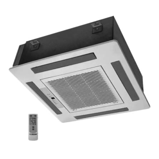
- Page 1 MUND CLIMA ® SPLIT CASSETTE COOL ONLY: MUCS-18 C HEAT PUMP: MUCS-18 H User's manual...
-
Page 2: Table Of Contents
CONTENT Operation mechanism and working range Names and functions of parts Safety cautions Remote control operation procedure Optimum operation Trouble shooting Installation notes Care and maintenance Technical specifications Installation accessories and drawings Indoor unit installation Outdoor unit installation Test and check items after installation Thank you purchasing this MUNDOCLIMA air conditioner. -
Page 3: Operation Mechanism And Working Range
Operation mechanism and working range. Working temperature range. Indoor side DB/WB ( ) Outdoor side DB/WB ( ) maximum cooling 43/26 32/23 minimum cooling 21/15 21/15 maximum heating 24/18 27/- minimum heating 20/- -5/-6 Schematic diagram of refrigeration 1. Schematic diagram of cooling type 2. -
Page 4: Names And Functions Of Parts
Names and functions of parts. Indoor unit Outdoor unit... -
Page 5: Safety Cautions
Safety cautions Read the following instructions carefully before use. Warning Avoid direct air flow to your body and avoid Check whether the installed stand is still firm excessive heating or cooling,which may make enough after the unit has operated for a long you feel uncomfortable and do harm to your time. - Page 6 Safety cautions Warning Do not check or repair during the unit is Do not use other operating. It is very dangerous. heating equip- ment near the air conditioner. It will affect the cooling perfor- mance. Never place objects near the air intake and the air outlet of the unit. It may affect performance or stop operation of the unit.
-
Page 7: Remote Control Operation Procedure
Remote control operation procedure Name and Function-Remote control Note: Be sure that there are no obstructions. Don’t drop or throw the remote controller. Don’t place the remote controller directly in the sunlight. SWING button When it is pressed, the louvers button start to rotate automatically and P r e s s t h i s b u t t o n t o... - Page 8 Remote control operation procedure Name and Function-Remote control. (Remove the cover) Note: This type of remote controller is a kind of new current controller. some buttons of the controller which are not available to this Air conditioner will not be described below.
- Page 9 Remote control operation procedure COOL mode operation procedure According to difference between room temp. and set temp., microcomputer can control cooling on or not. If room temp. is higher than set temp., compressor runs at COOL mode. If room temp. is lower than set temp., compressor stops and only indoor fan motor runs. Set TEMP.
- Page 10 Remote control operation procedure HEAT mode operation procedure If room temp. is lower than set temp., compressor runs at HEAT mode; If room temp. is higher than set temp., compressor and outdoor fan mortor stop, only indoor fan mortor runs. Set TEMP.
- Page 11 Remote control operation procedure DRY mode operation procedure If room temp. is lower than set temp., compressor ,outdoor and indoor fan mortor stop. If room temp. is between of set temp., Air conditioner is drying.If room temp. is higher than set temp., it’s at COOL mode. Set TEMP.
- Page 12 Remote control operation procedure AUTO mode operation procedure At AUTO mode operation, standard TEMP. is 25 for COOL mode and 20 for HEAT mode. 1.Plug in,Press 1/0 button, then air conditioner is turned on. 2.According to room temp.,micro- computer can automatically set operation mode,so as for best effect.
- Page 13 Remote control operation procedure TIMER mode operation procedure At stopping,press TIMER ON button, set ON TIME in range of 0 to 24 hour to start the unit automatically. At operating,press TIMER OFF button.set OFF TIME in range of 0 to 24 hour to stop the unit automatically.
- Page 14 Remote control operation procedure SLEEP mode operation procedure When the unit is cooling or drying, if SLEEP operation is set, TEMP. would increase 1 in 1 hour and 2 in 2 hour. Indoor fan motor runs at low speed. When the unit is heating , if SLEEP operation is set, TEMP. would decrease 1 in 1 hour and in 2 hours.
- Page 15 Remote control operation procedure How to insert batteries 1. Remove the cover from the back of the remote controller. 2. Insert the two batteries ( Two AAA dry - cell batteries ) and press but- ton “ACL”. 3. Re - attach the cover. Note: Don’t confuse the new and worn or different types of...
-
Page 16: Optimum Operation
Optimum operation Adjust the room temperature properly Adjust the room temperature properly for a comfortable environment. Never place anything under the indoor unit that is to be kept dry. Water may drop from the indoor unit when the humidity is over 80% or when the drainage outlet is clogged. Turn off the main power supply swittch when it is not to be used for long periods of time When the main power switch is truned on, some watts of electricity is being used even if the system is not operating. -
Page 17: Trouble Shooting
Trouble shooting Warning * In case of something abnormal (such as bad smell), shut off the power switch immediately and contact service center. * Do not repare the air conditioner by yourself. Because wrong repair may cause fire, please contact service center. Check these items shown below before contacting service center. - Page 18 Trouble shooting The following are not troubles “Trouble” Cause Restart right after stopping Once the unit is stopped, it will not operate The unit does not Press SET TEMP. and then release immediately. for about 3 minutes to protect it operate when Power is switched on Wati for 1 minute...
-
Page 19: Installation Notes
Installation notes Location Noise The air conditioner must be firmly installed and 3 4 Select a place with good ventilation or it may affect liability checks must be done every year. performance or increase noise. Avoid place whthin easy reach of young children. Install the air conditioner on a foundation that can Avoid other heat sources or dircect sun light. -
Page 20: Care And Maintenance
Care and maintenance Please pull out the power plug after you used the air conditioner. Warning Pull out the power plug before cleaning Do not splash water directly to the unit How to clean the air filter 1.Open the suction grille Use screwdriver screws the two screws. - Page 21 Care and maintenance 4.Fix the air filters Replace the air filter into its holder. Make sure that the air filter makes contact with the filter stopper when it is replaced into its holder. Shut the suction grille. Refer to step 1. How to clean the suction grille 1.Open the suection grille.
- Page 22 Care and maintenance Before starting the air conditioner for the first time in the season 1.Check to make sure no objects obstructing the intake and outlets parts on both the indoor and outdoor units. 2.Check to make sure ground wire is connected and that it is not damaged.
- Page 23 Care and maintenance Power supply and wiring requirement 1. Power frequency of air-conditioner should be 60Hz, voltage: AC 230V±10% If voltage are over may cause the parts of electric equipment damaged. If the voltage are too low may cause shake on compressor, it may let the cooling system damaged, and also, the compressor and parts will not work.
- Page 24 Care and maintenance Caution 1. Please check the earth connection before running test. 2. Voltage should be following the requirement. The voltage should not be too big after the running test (normally, 9000BTU unit not over 15V, 18000BTU unit not over 10V, 28000BTU unit not over 5V. 3.
-
Page 25: Technical Specifications
Technical specifications Technical specifications Model MUCS-18 C MUCS-18 H Functions Cooling Cooling/heating Cooling capacity 5000 5000 Heating capacity — 5500 Rated voltage and frequency 220/230V 50Hz Cooling/Heating Input current 10 / — 10 / 9.5 Maximum Current input Cooling/Heating Rated power 2.8 / —... -
Page 26: Installation Accessories And Drawings
Installation accessories Accessories Name Shape Quantity Notes Drainage hose For indoor side pipe joint Clamp For hole Nylon fastener L=200 Washer Paper pad for installaition Use for Paper pad for Screws ST4.8 13-F installation Heat preservation Sponge for pipe Encase the tie-in Big sealing pad Sealing pad Small sealing pad... -
Page 27: Installation Accessories And Drawings
Installation accessories and drawings Installation drawings Indoor unit Outdoor unit Note: Air conditioner must be installed by skilled personnel according to this manual. -
Page 28: Indoor Unit Installation
Indoor unit installation Location 1.Do not place object near the air oulet so that conditioned air can reach the whole room. 2.Be sure to install the indoor unit firmly and horizontly. 3.Select the place that can support 4 times of the indoor unit’s weight and will not increase noise and vibration. 4.Select a place easy to drain water and connect with the outdoor unit. - Page 29 Indoor unit installation Fig.5 Hanging preparations (1) Install special nut A, then special nut B onto the hanging bolt. (Fig.6) (2) Raise the body and mount its hooks onto the hanging bolt between the special nuts. (Fig.6) (3) Turn special nut B to adjust the height of the body. (Fig.6) (4) Leveling a level, or vinyl hose filled with water, fine adjust so that the body is level.
- Page 30 Indoor unit installation Fig.7 Installing drain pipe NOTE: Install the drain pipe. Install be drain pipe with downward gradient (1/50 to 1/100) and so there are no rises or traps in the pipe. Use general hard polyvinyl chloride pipe (VP25) [outside diameter 1-1/4” (32mm)] and connect it with adhesive (polyvinyl chloride) so that there is no leakage.
- Page 31 Indoor unit installation Connecting the pipes Besure to use both a spanner and wrench together as shown in the drawing during connecting or disconnecting pipes to/from the unit. The pipe of water-in/out is pipe thread G3/4.The surface of thread should be enlaced by the two or three-circles trap. After the water-in pipe and water-out pipe is connecting tightly,starting the water pump,then checking it’s airproof performance.
-
Page 32: Electrical Wiring
Indoor unit installation Electrical wiring How to connect wiring to the terminals A. For solid core wiring (or F-cable) (1) Cut the wire end with a wire cutter or wire-cutting pkiers, then stuip the insulation to about 15/16” (25mm) of expose thn solid wire. - Page 33 Indoor unit installation Indoor unit side Remove the control box cover and install the connection cord. (Fig. 12 and 13) Fig.12 Control box cover Fig.13 brown blue 3-core rubber cable (to outdoor unit)
- Page 34 Indoor unit installation Bolting the grille assembly to the body Install the grille assembly to the body with the four bolts,spring washers,and washers. Fig.16 Washer Spring washer Bolt No gap between ceiling and grille around entire periphery. Wireless unit connection wire wiring (1).
- Page 35 Indoor unit installation Fig.18 Part A detail view Installing/Removing the intake grille 1. Installing the intake grille (1) Full insert the intake grille hooks into the rectangular holes in the panel. Fig.19 (2) Close the intake grille,then slide the tow grille stoppers outward. Fig.20...
- Page 36 Indoor unit installation 2.Removing the intake grille (1) Slide the two grille stoppers inward,and then open the iotake grill. Fig.21 Grille stopper (2) Remove the geille hook screws, and then open the intake grille. Fig.22 Grille hook (3) Open the intake grille so that it is at an angle of 20° to 40° ,and then remove the grille. Fig.23 Caution: (1)the louver angle cannot be changed if the power is not no, (It moved by hand,ir may be damaged.)
- Page 37 Indoor unit installation Connection of refrigerant pipe Besure to use both a spanner and torque wrench together as shown in the drawing,connecting or disconnecting pipes to/from the unit. Refer to table 1 to determine the proper tightening torque (over tightening may damage the flare and cause leaks.) When conecting the flare nut,coat the flare both inside and outside with refrigerating machine oil and initially tighten by hand 3 or 4 turns.
-
Page 38: Outdoor Unit Installation
Outdoor unit installation Selecting installation site Select an installation site where the folliwing conditions are satisfied and that meets with your customer’s approval. Places which are well-ventilated. Safe places which can withstand the unit’s weight and vibration and where the unit can be installed level. Places where the unit does not bother next-door neighbors. - Page 39 Outdoor unit installation Electric wiring (1) Read the name plate carefully,then arrange wiring according to the “WIRING DIAGRAM”. (2) A circuit breaker capable of shutting down power supply to the entire system must be installed. (3) Earth properly. (4) All wiring must be perfomed by a skilled electrican according to the “WIRING DIAGRAM”. Wrong wiring may cause fire of electric shock.
-
Page 40: Test And Check Items After Installation
Test and check item after installation Test operation 1. Prepare for test (1) Do not turn on the power switch before all installation is finsihed. (2) Connect wires corectly and firmly. (3) Open the check valve. (4) Remove all dust. 2.
Need help?
Do you have a question about the MUCS-18 C and is the answer not in the manual?
Questions and answers