
Related Manuals for mundoclima H14 Series


Summary of Contents for mundoclima H14 Series
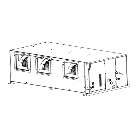
- Page 1 High Pressure Duct H14 Series Installation and owner's manual MUCHR-H14-I UI21580 ~ UI21586 www.mundoclima.com...
-
Page 3: Table Of Contents
Contents About The Documentation About This Document / 1 Safety Instructions / Safety Warning Safety Precautions / 4 Electric Safety Requirements / About The Refrigerant / Operation Operation Precautions / Optimum Operation / 10 Symptoms That Are Not Faults / 12 Display Box (Optional) / Disposal / 14 Installation... -
Page 4: About The Documentation
About The Documentation About This Document NOTE Make sure that the user has the printed documentation and ask him/her to keep it for future reference. Target audience Authorised installers + end users NOTE This appliance is intended to be used by expert or trained users in shops, in light industry, and on farms, or for commercial and household use by lay persons. -
Page 5: Safety Instructions
Safety Instructions Please thoroughly read and ensure that you fully understand the safety precautions (including the signs and symbols) in this manual, and follow relevant instructions during use to prevent damage to health or property. Safety Signs Indicates a hazard with a high level of risk which, if not avoided, will result in death or DANGER serious injury. - Page 6 DANGER These instructions are exclusively intended for qualified contractors and authorised installers • Work on the refrigerant circuit with flammable refrigerant in safety group A2L may only be carried out by authorised heating contractors. These heating contractors must be trained in accordance with EN 378 Part 4 or IEC 60335-2-40, Section HH.
-
Page 7: Safety Warning
Safety Warning WARNING CONTENTS Ensure Proper Professional Only Earthing PROHIBITION SIGNS No Laying No Strong Currents No Open Flame; No Acid or Inflammable Thing Fire, Open Ignition Alkali Materials Source and Smoking Prohibited Safety Precautions DANGER In the event of refrigerant leakage, smoking and open flames are prohibited. Disconnect the main power switch immediately, open windows to allow ventilation, keep away from the leakage point, and contact your local dealer or technical support to request a professional repair. -
Page 8: Electric Safety Requirements
CAUTION This appliance can be used by children aged from 8 years and above and persons with reduced physical, sensory or mental capabilities or lack of experience and knowledge if they have been given supervision or instruction concerning use of the appliance in a safe way and understand the hazards involved. Children shall not play with the appliance. -
Page 9: About The Refrigerant
About The Refrigerant WARNING The following applies to R32 refrigerant systems. Prior to beginning work on systems containing flammable refrigerants, safety checks are necessary to ensure that the risk of ignition is minimized. For repair to the refrigerating system, the following precautions shall be complied with prior to conducting work on the system. - Page 10 During repairs to sealed components, all electrical supplies shall be disconnected from the equipment being worked upon prior to any removal of sealed covers, etc. If it is absolutely necessary to have an electrical supply to equipment during servicing, then a permanently operating form of leak detection shall be located at the most critical point to warn of a potentially hazardous situation.
- Page 11 i) Do not exceed the maximum working pressure of the cylinder, even temporarily. j) When the cylinders have been filled correctly and the process completed, make sure that the cylinders and the equipment are removed from site promptly and all isolation valves on the equipment are closed off. k) Recovered refrigerant shall not be charged into another refrigeration system unless it has been cleaned and checked.
-
Page 12: Operation
Operation Operation Precautions WARNING If the unit will be not used for a long time, disconnect the main power switch. Otherwise, an accident may occur. The installation height of the air conditioner shall be at least 2.5m above the ground to avoid the following risks: 1. -
Page 13: Optimum Operation
Disposal: Do not dispose of this product as unsorted municipal waste. Collection of such waste separately for special treatment is necessary. Do not dispose of electrical appliances as unsorted municipal waste, use separate collection facilities. Contact your local government for information regarding the collection systems available. If electrical appliances are disposed of in landfills or dumps, hazardous substances can leak into the groundwater and get into the food chain, damaging your health and well-being. - Page 14 CAUTION The downward direction of the louvers of the outlet grille during cooling operation may cause condensation on the air outlet and guide louvers surface. In Heating Mode To improve the heating effect in the lower parts of a room, adjust the louvers of air outlet grille downwards. Operating Range Use the unit in the following temperature and humidity ranges for safe and effective operation.
-
Page 15: Symptoms That Are Not Faults
Symptoms That Are Not Faults Normal Protection Of The Air Conditioner During operation, the following phenomena are normal and do not require maintenance. When the power switch is on, the air conditioner starts 3-5 minutes after it is turned ON again Protection in case it was turned off just before. - Page 16 "Self-cleaning" sound of icing During self-cleaning, there may be a slight clicking sound from the melting thin ice about 10 minutes. Noise of Indoor unit ① A continuous low "hissing" sound is heard when the system is in "Auto", "Cool", "Dry", and "Heat"...
-
Page 17: Disposal
Display Box (Optional) Display functions: ① In Standby mode, the main interface displays “---”. ② When starting up in Cooling or Heating mode, the main interface displays the set temperature. In Fan mode, the main interface displays the indoor temperature. In Dry mode, the main interface displays the set temperature, and when the humidity* is set, the set humidity value is displayed on the wired controller. -
Page 18: Installation
Installation Carefully read this manual before installing the indoor unit. Installation Precautions WARNING Make sure to carry out the installation according to local legislation. Ask your local dealer or professionals to install the product. This unit must be installed by pqualified persons. Users MAY NOT install the unit themselves; otherwise, faulty operations may cause the risks of fire, electrical shock, injury, or leakage, which could harm you or others or damage the air conditioner. - Page 19 Before and after installation, exposing the unit to water or moisture will cause electrical short circuit. Do not store the unit in a humid basement or expose it to rain or water. Make sure the installation base and lifting are robust and reliable; Insecure installation of the base may cause the air conditioner to fall, leading to an accident.
- Page 20 Precautions For Transporting And Lifting The Air Conditioner Before transporting the air conditioner, determine the path that will be used to move it to the installation site. Do not unpack the air conditioner until it is transported to the installation site. When unpacking and moving the air conditioner, must hold the Lifting Lugs and do not apply force to other parts, especially the refrigerant piping, drain pipe and plastic accessories, so as to avoid damaging the air conditioner and causing personal injury.
- Page 21 Recommended Installation Sites It is recommended to install the air conditioner according to the design drawing of the HVAC engineer. The selection principle for the installation site is as follows: Ensure that the airflow in and out of the indoor unit is reasonably organized to form an air circulation in the room. Prevent the air conditioner from blowing directly at the human body.
- Page 22 Layout Installation layout 14 15 *Air outlet grille *Air outlet duct *Soft flexible duct Liquid pipe Drain pipes for models Gas pipe without a water pump Drain pipes for models Display box (optional) *Connection wires with a water pump Wired controller (optional) Remote controller (optional) Access hole *Power supply cable and earth wires...
- Page 23 Product Dimensions (Unit: mm) Capacity (kW) 5/8-18 UNF Φ19.1 20.0≤kW≤22.4 3/4-16 UNF Φ22.2 22.4<kW≤28 3/4-16 UNF Φ25.4 28<kW≤33.5 Appearance and dimensions of the air inlets, piping, drain pipes, power cable hole and communication wire hole: Φ30 (inner diameter) Matching PVC pipe (outer B (gas side, inner diameter Φ32) diameter)
- Page 24 Capacity (kW) 3/4-16 UNF Φ25.4 33.5≤kW≤40.0 7/8-14 UNF Φ28.6 40.0<kW≤56.0 Appearance and dimensions of the air inlets, piping, drain pipes, power cable hole and communication wire hole: Φ30 (inner diameter) Matching PVC pipe (outer diameter Φ32) 2×Φ22 B (gas side, inner diameter) Connection process pipe...
-
Page 25: Installation Materials
Installation Materials Accessories List of accessories Installation And Flare Nut X 1 Drain Pipe X 1 Cable Tie X 4 Thermal Insulation Pipe X 2 Operation Manual X 1 (Make sure to hand it over For use in the installation of Unavailable for units with a To tighten the drain hose tightly Used for insulation and... - Page 26 Locally Purchased Accessories Connecting pipe (Unit: mm) Piping Liquid side Gas side Capacity(kW) 20.0≤kW≤22.4 Φ9.52×0.7 Φ19.1×0.75 22.4<kW≤28.0 Φ12.7×0.75 Φ22.2×1.0 28.0<kW≤40.0 Φ12.7×0.75 Φ25.4×1.2 40.0<kW≤56.0 Φ15.9×0.75 Φ28.6×1.2 For connection of the indoor unit refrigerant system, it is recommended Remarks to use a soft connecting pipe (T2M), with the length selected according to the actual situation.
-
Page 27: Preparations Before Installation
Preparations Before Installation Unpacking Check After unpacking, check whether the packing materials are in good ① The red condition, whether the accessories that come with the product are dot bulges Sealing complete, whether the air conditioner is intact, whether the surfaces of the heat exchanger and other parts are not worn, and whether there are oil stains on the stop valves of the unit. - Page 28 Bottom view (Unit: mm) Wall ≥500mm Maintenance space Access hole Electric control assembly ≥600mm Maintenance space Side view Air outlet Access hole ≥600 ≥600 Space for removing Space for filter and inlet Air inlet the front panel duct maintenance Caution The distance between the indoor unit and the ceiling slab (B) shall be greater than 50mm to install the air duct.
-
Page 29: Indoor Unit Installation
Indoor Unit Installation WARNING Install the air conditioner in a location with sufficient strength to support the weight of the unit. Take reinforcement measures when necessary. The unit may fall and cause personal injury if the location is not strong enough. Unstable installation may cause the unit to fall and cause an accident. - Page 30 Refer to the following figure on installation using the suspension bolts. With steel frame Sites with concrete slabs Use embedded bolts and anchor bolts Directly set and use an angle iron for support. Suspension bolts Angle iron for support Suspension bolts Indoor Unit Installation CAUTION The indoor unit must not be too close to the ceiling.
-
Page 31: Refrigerant Connecting Piping Installation
Use a transparent hose to observe water level (principle of communicating vessels) and verify the tilt angle of the unit in the length direction. It shall be installed level or at an angle within 1° towards the drainage side. (For units without a drain pump, ensure a slope of 1/100 towards the drainage side. Do not tilt towards the non-drainage side.) Otherwise, water cannot drain smoothly and leaks can easily occur. - Page 32 Pipe Layout ① The deformed pipe area must not exceed 15% . ② A protective sleeve should be installed at the wall or floor hole. ③ The weld joint must not be inside the insulation. ④ The drill hole on the external wall must be sealed. ≥...
- Page 33 CAUTION The bending angle should not exceed 90°; otherwise, wrinkles will be formed in the pipe, which can easily break. The bending radius should not be smaller than 3.5D (pipe diameter) and should be as large as possible to prevent the pipe from becoming flattened or crushed. When mechanically bending the pipe, the pipe bender inserted into the connecting pipe must be cleaned.
- Page 34 90°±4 A (mm) Outer diameter (mm) Max. Min. Φ6.35 Φ9.52 12.4 12.0 R0.4–0.8 Φ12.7 15.8 15.4 Φ15.9 19.1 18.6 Φ19.1 23.3 22.9 Handle Yoke Cone Connecting pipe Clamp handle Red arrow mark Nut fastening Connect the indoor unit first, then connect the outdoor unit.Before tightening the flare nut, apply refrigeration oil on the inner and outer surface of the pipe flare (must use refrigeration oil compatible with the refrigerant for this model), and turn it 3 or 4 turns by hand to tighten it.When connecting or removing a pipe, use two wrenches at the same time.
- Page 35 CAUTION When flared joints are reused indoors,the flare part should be re-fabricated. Pipe size (mm) Tightening torque [ N.m (kgf.cm)] Φ6.35 14.2–17.2 (144–176) Φ9.52 32.7–39.9 (333–407) Φ12.7 49.5–60.3 (504–616) Φ15.9 61.8–75.4 (630–770) Φ19.1 97.2–118.6 (990–1210) CAUTION Excessive torque will damage the flared mouth and nut, and too small torque cannot tighten the nut, which will cause refrigerant leakage.
- Page 36 Leak Detection The leak test must satisfy the specifications of EN378-2. To check for leaks: Vacuum leak test ① Evacuate the system from the liquid and gas piping to –100.7 kPa (–1.007 bar)(5 Torr absolute) for more than 2 hours. ②...
-
Page 37: Drain Pipe Installation
Drain Pipe Installation CAUTION Before installation of the drain pipe, determine its direction and elevation to avoid intersection with other pipelines to ensure that the slope is straight. The highest point of the drain pipe should be equipped with a vent port to ensure the smooth drainage of condensate water, and the vent port must face downwards to prevent dirt from entering the pipe. - Page 38 Thermal insulation pipe PVC water drain pipe (outer diameter: 32mm) The thermal insulation pipe is closely attached to the unit. Drainage outlet for water pump Drain hose Thermal insulation pipe There is a large gap PVC water drain pipe between the thermal insulation pipe and the (outer diameter: 32mm) Teflon...
- Page 39 The end of the drain pipe must be more than 50mm above the ground or from the base of the water drainage slot. In addition, do not submerge it in water. To drain the condensed water directly into a ditch, the water drain pipe must bend upwards to form a U-shaped water plug to stop odors from entering the room via the water drain pipe.
- Page 40 How to drain water without the drain pump: (Unit: mm) 800~1000 Slope > 1/100 Method to connect the drain pipe for a single unit Air outlet ≥50 ≥50 Slope > 1/100 Plug Drain pipes from multiple units are connected to the main drain pipe to be drained through the sewage pipe.
-
Page 41: Air Duct Installation
Water injection amount: (Unit: ml) Indoor unit capacity (kW) Water injection amount 20.0≤kW≤33.5 4000 33.5<kW≤56.0 5000 Water injection Air Duct Installation Please use locally purchased air ducts and soft air ducts (Use environmentally friendly, odorless materials, otherwise the air conditioner may generate odor when it runs). Install the flange at the air return side, and use aluminum foil tape to seal the connection part between the flange and the air duct to avoid air leakage. - Page 42 The air outlet duct can be installed in two ways: Method 1: Connect an air duct to each air outlet. Air outlet Air inlet Air outlet Method 2: Remove the flange at the air outlet and connect the air duct as a whole (refer to the product dimensions in this Manual for the dimensions of the air duct installation hole).
- Page 43 Connection between air vent and air duct wrong Air vent size and position wrong Connection between air Air vent vent and air size wrong duct wrong Air outlet Air outlet Return air inlet not opened Return air inlet Air vent position wrong Air vent size and position correct Air vent size correct...
-
Page 44: Electrical Connection
Electrical Connection DANGER The power supply must be cut off before any electrical work is carried out. Do not conduct electrical work when the power is on; otherwise, it may cause serious personal injury. The air conditioning unit must be earthed reliably and must meet the requirements of the local country/region. - Page 45 Electrical Characteristics Electric specifications of the indoor unit Indoor Fan Motor Capacity Frequency Voltage Rated Motor (kW) (Hz) (A) (A) Output (W) 8.19 20.0 6.55 8.19 22.4 6.55 8.19 25.2 6.55 8.19 28.0 6.55 220~240 8.31 33.5 6.65 12.98 2300 40.0 10.38 12.98...
- Page 46 CAUTION All weak point connection points meet SELV, such as X1, X2, P, Q, E, CN18, CN55 etc. Wiring ② Open the indoor unit's electric control box cover. ① ① ① Remove the four screws at the positions shown in the figure; ①...
- Page 47 Power supply cable connection ① Connection between the power supply cable and power supply terminal Electric control box sheet The power supply terminal of the indoor unit is fixed on the metal part terminal block, The live and neutral wires are connected according to the terminal block logos "L"...
- Page 48 ② Power supply cable system connection Indoor unit: Power supply for indoor unit Communication wires × × Circuit breaker Power supply cable Distribution box Master outdoor unit Indoor unit 1# CN22 Use shielded cables and earth the shield layer. NOTE H14 indoor units *: with H14 printed on the packaging carton...
- Page 49 Communication wiring connection ① Selection of communication method for indoor units Optional communication method Indoor unit type Remarks between indoor units and outdoor unit 1. The indoor units need to be powered uniformly. RS-485 (PQE) 2. The communication cables must be connected MUCHR-H14-I communication in serial.
- Page 50 CAUTION Please select the communication wiring according to the requirements in the above reference table. Use shielded cables for communication when strong magnetism or interference is present. On-site wiring must comply with the relevant regulations of the local country/region and must be completed by professionals.
- Page 51 ③ Indoor unit and outdoor unit communication P/Q/E communication Single unit: Use a shielded cable for the P/Q/E communication and properly earth the shield layer. P, Q, and E ports are located at terminal block "CN6" of the main control board. There is no distinction between negative and positive electrodes.
- Page 52 CAUTION When P/Q/E communication is used, the indoor units need to be powered uniformly. Use only shielded cables for P/Q/E communication. Otherwise, the indoor unit and outdoor unit communication may be affected. A matching resistor needs to be added to the last indoor unit on the PQ (in the accessory bag of the outdoor unit).
- Page 53 ④ X1/X2 communication cable connection The X1X2 communication wiring is mainly connected to the wired controller to achieve one controller per indoor unit and two controllers per indoor unit. The total length of the X1X2 communication wiring can reach 200 meters. Please use shielded wires, but the shield layer cannot be earthed. X1 and X2 ports are located at terminal block "CN6"...
- Page 54 ⑤ D1D2 communication wiring connection (limited to outdoor unit and system configuration) Achieving one-to-multiple and two-to-multiple functions of the indoor unit wired controller through D1D2 communication (a maximum of 2 sets) D1D2 communication is 485 communication. The one-to-more and two-to-more functions of the indoor unit wired controller can be achieved through D1D2 communication, as shown in the figure below: Indoor unit 2# Indoor unit 1#...
- Page 55 External boards connection (limited to outdoor unit and system configuration) The external boards are connection module outside the main control board, including a display box, Switch module, 1# Expansion board and 2# Expansion board. ① Connection of Display Box The display box is connected to the main control board through a 4-core cable, and is connected to the "CN30"...
- Page 56 Alarm signal and Sterilization module Refer to the following figure for the wiring of alarm signal and Sterilization module. Main CAUTION CN22 control board Output voltage: 220 VAC; The output voltage is 220-240V~. Maximum output power: 220 W Strong current sterilization module Alarm signal output Output voltage: 220 VAC;...
-
Page 57: Error Codes
Error Codes Error Codes And Definitions The error code is displayed on the display box and the wired controller display. Definition Error code Digital display Emergency stop DANGER R32 refrigerant leaks, requiring shutdown immediately Outdoor unit fault Interlocking control Heat Recovery Ventilation Unit fault( in-series application) The Humidity Unit fault Interlocking control Heat Recovery Ventilation Unit fault(non-serial application) The AHU Kit slave unit fault... - Page 58 Definition Error code Digital display Abnormal communication between the indoor unit and outdoor unit Abnormal communication between the indoor unit main control board and fan drive board Abnormal communication between the indoor unit and wired controller Abnormal communication between the indoor unit and Wi-Fi Kit Abnormal communication between the indoor unit main control board and display board Abnormal communication between the AHU Kit slave unit and master unit Number of AHU Kits is not the same as the set number...
- Page 59 Definition Error code Digital display The built-in room temperature sensor of the wired controller short-circuits or cuts off The wireless temperature sensor short-circuits or cuts off The external room temperature sensor short-circuits or cuts off Tcp (pre-cooled fresh air temperature sensor) short-circuits or cuts off Tph (pre-heated fresh air temperature sensor) short-circuits or cuts off TA (outlet air temperature sensor) short-circuits or cuts off Outlet air humidity sensor fault...
- Page 60 Definition Error code Digital display Low bus voltage fault High bus voltage fault Phase current sample bias error Motor and indoor unit are unmatched IPM and indoor unit are unmatched Motor startup failure Motor blocking protection Speed control mode setting error Phase lack protection of motor Operating Status Codes And Definitions (Non-error) Definition...
- Page 61 Spot Check Description Use the bi-directional communication wired controller (for example, WDC3-86S) to activate the spot check function in the following steps: Check No. ① On the main page, hold " " and "▲" for 2s to Spot check enter the query page. The wired controller parameters displays "CC".
-
Page 62: Settings
Settings ESP Setting Use the bi-directional communication wired controller (for example, WDC3-86S) to set the unit external static pressure, which can be divided into the following two situations: Constant air flow mode Indoor units that are equipped with a constant air flow function are set to the constant air flow mode when they leave the factory. - Page 63 Air Pressure Curve Constant air flow - self-adaptive 20.0 kW / 22.4kW / 25.2kW / 28.0 kW 33.5 kW 2000 2500 3000 3500 4000 4500 5000 2000 2500 3000 3500 4000 4500 5000 Air flow rate (m Air flow rate (m 40.0 kW / 45.0 kW 56.0 kW 3500...
- Page 64 Constant speed mode The bi-directional communication wired controller must be used to set the unit's external static pressure parameters to overcome the air outlet resistance. The steps are as follows: ① On the main page, hold " " and " "...
- Page 65 Air Pressure Curve Constant speed 20.0kW / 22.4kW / 25.2kW / 28.0kW 33.5kW Setting *1: 400Pa MAX Setting *1: 400Pa MAX Setting *2: 300Pa Setting *2: 300Pa Setting *3: 200Pa DEFAULT Setting *3: 200Pa DEFAULT Setting *4: 100Pa Setting *4: 100Pa Setting *5: 50Pa Setting *5: 50Pa Fan speed 1-*4...
-
Page 66: Test Run
NOTE Parameters can be set while the unit is powered on or powered off. On the parameter setting page, the wired controller does not respond to a remote signal, and does not respond to the app remote control signal. When it is in the parameter settings page, the mode, fan speed, and switch buttons are invalid. Please refer to the remote controller manual for the setting parameters of the remote controller. - Page 67 Pass/Fail Check list Fuses, circuit breakers, or protection devices Check that the fuses, circuit breakers, or the locally installed protection devices are of the specified size and type. Do not bypass a fuse and a protection device. Internal wiring Visually check the electrical component box and the inside of the unit for loose connections or damaged electrical components.
-
Page 68: Safety Warning
Maintenance And Service Safety Warning WARNING For safety reasons, always turn off the air conditioner and turn off the power before cleaning the air conditioner. Do not disassemble or repair the air conditioner by yourself; otherwise, it may cause fire or other hazards. Only professional service personnel can carry out the maintenance. - Page 69 Procedure Remove the air inlet grille. For duct type air conditioners, open the air inlet grille as shown in the figure. Remove the filter. Remove the filter (if any) at the air inlet of the air conditioner (the filter is optional). NOTE Only authorised installer or service agent can change and disassemble the filter.
- Page 70 Cleaning Air Outlets And Exterior Panels Wipe the air outlet and panel with a dry cloth. If a stain is hard to remove, clean it with clean water or neutral detergent. CAUTION Do not use gasoline, benzene, volatile agents, decontamination powder or liquid insecticides. Otherwise, the air outlet or panel may become discolored or deformed.
-
Page 71: Service
Service Step To Dismantle The Fan The fan propeller casing inside the unit can be maintained by removing the cover or the front panel. Method 1: Remove the cover Remove the flange. Remove the cover assembly. Cover assembly Flange Loosen the propeller casing screw. Remove the fan propeller casing. - Page 72 Method 2: Remove the front panel Remove the flange. Remove the front panel. Front panel Flange Loosen the propeller casing screw. Remove the fan propeller casing.
- Page 73 Step To Dismantle The Motor For motor maintenance, remove the fan propeller casing first with one of the methods above. Follow the steps below to remove the motor. Loosen the motor screw. Remove the motor. Step To Dismantle The Drain Pump (For Units With Uumps), Temperature Sensor And Electronic Expansion Valve Remove the electric control box cover and Remove the pipe clamp board.
- Page 74 Step To Dismantle The Main Control Board Remove the electric control box cover. Check the circuit, components and other problems or replace the main board. After replacing the main board, use the after-sale tool to scan the QR code on the electric control box, and reset theparameter.
- Page 75 Attached Page ErP Information Fan Types Centrifugal fan ErP Directive 2009/125/EC Directive (or Standard) for Regulation COMMISSION REGULATION (EU) No 327/2011 Model Name ZKSN-2300-8-2+LX-305*203*20-56J Rev. Rev. Prepare by Specified Information of Fan: Information Item Comment ηtarget = 39.9% Overall efficiency (ηe) = 44.7% Pass or not (Criteria: ηe ≧ηtarget ) Pass...
- Page 76 ErP Information Fan Types Centrifugal fan ErP Directive 2009/125/EC Directive (or Standard) for Regulation COMMISSION REGULATION (EU) No 327/2011 Model Name ZKSN-920-8-12-2L+LX-305*203*20-56J Rev. Rev. Prepare by Specified Information of Fan: Information Item Comment ηtarget = 37.3% Overall efficiency (ηe) = 44.2% Pass or not (Criteria: ηe ≧ηtarget ) Pass...
- Page 77 ErP Information Fan Types Centrifugal fan ErP Directive 2009/125/EC Directive (or Standard) for Regulation COMMISSION REGULATION (EU) No 327/2011 Model Name ZKSN-920-8-12-2L+LX-305*203*20-56J Rev. Rev. Prepare by Specified Information of Fan: Information Item Comment ηtarget = 37.2% Overall efficiency (ηe) = 44.3% Pass or not (Criteria: ηe ≧ηtarget ) Pass...
- Page 78 C/ ROSSELLÓ, 430-432 08025 BARCELONA ESPAÑA / SPAIN (+34) 93 446 27 80 SAT: (+34) 93 652 53 57 www.mundoclima.com...
Need help?
Do you have a question about the H14 Series and is the answer not in the manual?
Questions and answers