Chapters
Table of Contents

Related Manuals for mundoclima UE-MUCR-12-H8


Summary of Contents for mundoclima UE-MUCR-12-H8
-
Page 1: Service Manual
SUPER INVERTER H8 Service manual MUCSR-H8 MUSTR-H8 MUCR-H8 MUCOR-H8 CL20260 to CL20288 Thank you very much for purchasing our products. CL20395 Please read this manual carefully before installing English and using the unit. www.mundoclima.com... - Page 2 Contents Part 1 General Information ....................1 Part 2 Indoor Units ......................... 5 Part 3 Outdoor Units ......................94 Part 4 Installation ....................... 108 Part 5 Electrical Control System ..................140 ※The specifications, designs, and information in this book are subject to change without notice for product improvement.
-
Page 3: Part 1 General Information
General Information Part 1 General Information 1. Model Lists ................... 2 2. External Appearance ................3 2.1 Indoor Units ....................... 3 2.2 Outdoor Units ......................4 General Information... -
Page 4: Model Lists
Model Lists 1. Model Lists 1.1 Indoor Units R410A (capacity multiplied by 1000Btu/h) Type Function ● ● ● ● ● Super slim cassette Cooling and heating ● ● ● ● ● ● ● Duct Cooling and heating ● ● ● ●... -
Page 5: External Appearance
External Appearance 2. External Appearance 2.1 Indoor Units Super slim cassette Duct Compact Four-way cassette Ceiling-Floor Floor standing General Information... -
Page 6: Outdoor Units
External Appearance 2.2 Outdoor Units Single fan outdoor unit (Models 12 to 36) Double fan outdoor unit (Models 48 to 60) General Information... -
Page 7: Part 2 Indoor Units
Indoor Units Part 2 Indoor Units MUCSR-H8 (24 to 60) Cassette Type ……………………6 MUCR-H8 Duct Type ………………………..…………… ..46 MUSTR-H8 Ceiling & Floor Type ........49 MUCSR-H8 (12 to 12) Cassette Type (Compact) ..... 68 MUCOR-H8 Floor standing Type ........82 Indoor Units... -
Page 8: Table Of Contents
MUCSR-H8 (24 to 60) Cassette Type MUCSR-H8 (24 to 60) Cassette Type 1. Features ................7 2. Dimensions ..............10 3. Service Space ..............11 4. Wiring Diagrams ............12 5. Air Velocity Distributions (Reference Data) ....18 6. Electric Characteristics ..........21 7. -
Page 9: Features
Features 1. Features 1.1 Overview Compact design, super slim body size, less space requiring in installation Each louver can be separately controlled, more comfort air blowing is possible. Auto-lifting panel design, more convenient to clean and maintain the filter. (optional) Fresh air intake function ... - Page 10 Features Built-in draining pump Due to the improvement of structure, more convenient to repair or replace the draining pump. Draining Pump Built-in draining pump to make sure condensed water drain out reliably. 1.5 Terminals for alarm lamp and long-distance on-off controller connection are standard ...
- Page 11 Features 1.6 Twins Combination (18k-30k) The units can be installed as Twin systems: one outdoor unit can connect with two indoor units. The indoor units can be combined in any of the different available ratings. Indoor Units...
-
Page 12: Dimensions
Dimensions 2. Dimensions 92 92 Fresh air intake 4-install hanger Body Gas side Liquid side Wiring connection port E-parts box Service hole for Test mouth & Test cover draining pump Drain hole 92 92 92 92 Panel Unit: mm Model(kBtu/h) 24~36 48~60 Indoor Units... -
Page 13: Service Space
Service Space 3. Service Space >1000m m >1000mm Chart 3 Indoor Units... -
Page 14: Wiring Diagrams
Wiring Diagrams 4. Wiring Diagrams KJR-120C / WF-60A1 This symbol indicates the - - - - CODE:16022500000803 TO WIRE the actual element is optional MAGNETIC RING CONTROLLER shape shall prevail Inner Driver FUNCTION OF SWITCH DC Motor SWITCHFOR CCM UNIT ADDRESS ENC1 SWITCH (FOR POWER) - Page 15 Wiring Diagrams 4.1 Some connectors introduce: A For remote control (ON-OFF) terminal port CN23 and short connector of JR6 1. Remove the short connector of JR6 when you use ON-OFF function; 2. When remote switch off (OPEN), the unit would be off; 3.
- Page 16 Wiring Diagrams C. For new fresh motor terminal port CN8 1. Connect the fan motor to the port, no need care L/N of the motor; 2. The output voltage is the power supply; 3. The fresh motor cannot excess 200W or 1A, follow the smaller one; 4.
- Page 17 Wiring Diagrams Micro-Switch Introduce: A. Micro-switch SW1 is for selection of indoor fan stop temperature (TEL0) when it is in anti-cold wind action in heating mode. Range: 24 C, 15 C, 8 C, according to EEROM setting (reserved for special customizing). TEL0+16 Setting fan speed TEL0+14...
- Page 18 Wiring Diagrams C.Micro-switch SW3 is for selection of auto-restart function. Range: Active, inactive D. Micro-switch SW5 is for setting the master or slave unit when the unit is in twin connection. Range: Master no slave (Normal 1 drive 1 connection), Master (2 positions without difference), Slave E.Micro-switch SW6 is for selection of temperature compensation in heating mode.
- Page 19 Wiring Diagrams G. Dial-switch ENC1: The indoor PCB is universal designed for whole series units from 18K to 55K. This ENC1 setting will tell the main program what size the unit is. NOTE: Usually there is glue on it because the switch position cannot be changed at random unless you want to use this PCB as a spare part to use in another unit.
-
Page 20: Air Velocity Distributions (Reference Data)
Air Velocity Distributions (Reference Data) Air Velocity Distributions (Reference Data) 24K: Cooling: Heating: Indoor Units... - Page 21 Air Velocity Distributions (Reference Data) 30-36K: Cooling: Heating: Indoor Units...
- Page 22 Air Velocity Distributions (Reference Data) 48-60K: Cooling: Heating: Indoor Units...
-
Page 23: Electric Characteristics
Electric Characteristics Electric Characteristics Indoor Unit Power Supply Model Voltage MUCSR-24-H8 220-240V 198V 254V 220-240V 198V 254V MUCSR-30-H8 MUCSR-36-H8 220-240V 198V 254V MUCSR-48-H8 / MUCSR-48-H8T 220-240V 198V 254V MUCSR-60-H8 / MUCSR-60-H8T 220-240V 198V 254V Notes: MFA: Max. Fuse Amps. (A) Indoor Units... -
Page 24: Sound Levels
Sound Levels Sound Levels 1.4m Microphone Noise level dB(A) Model Noise Power dB(A) MUCSR-24-H8 MUCSR-30-H8 MUCSR-36-H8 MUCSR-48-H8 / MUCSR-48-H8T MUCSR-60-H8 / MUCSR-60-H8T Indoor Units... -
Page 25: Accessories
Accessories Accessories Name Shape Quantity Installation Fittings Installation paper board Tubing & Fittings Soundproof / insulation sheath Out-let pipe sheath Out-let pipe clasp Drainpipe Fittings Drain joint Seal ring Remote controller & Its Frame Remote controller & Its Frame(The product you Remote controller holder have might not be provided the following... -
Page 26: The Specification Of Power
The Specification of Power 9. The Specification of Power Model(Btu/h) 24000 30000 36000 Phase 1-phase 1-phase 1-phase Frequency 220-240V, 50Hz 220-240V, 50Hz 220-240V, 50Hz POWER Voltage POWER WIRING 3×2.5 3×2.5 3×4.0 (mm2) CIRCUIT BREAKER/Fuse (A) 30/20 40/30 40/30 Indoor/Outdoor Connecting Wiring 2×0.2 2×0.2 2×0.2... -
Page 27: Field Wiring
Field Wiring 10. Field Wiring Indoor Units... -
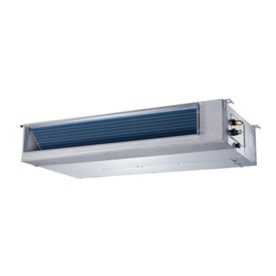
Page 28: Mucr-H8 Duct Type
MUCR-H8 Duct Type MUCR-H8 Duct Type 1. Features ................27 2. Dimensions ..............30 3. Service Space ..............31 4. Wiring Diagrams ............32 5. Static Pressure ............... 38 6. Electric Characteristics ..........44 7. Sound Levels ..............45 8. Accessories ..............46 9. -
Page 29: Features
Features Features 1.1 Higher Static Pressure As a ducted air conditioner with medium static pressure, it has the widest static pressure range. The maximum static pressure reaches 160 Pa 1.2 Slim Design The industry lowest height is designed to be fitted into tight roof spaces. *18K unit - 210mm,24K/36K unit - 249mm,48K unit -300mm Constant air volume control ... - Page 30 Features Air intake from bottom (Optional) Air intake from rear (Standard) 1.5 Communication wire connection MUCR-H8 uses two wires without polarity connection way, which almost has no mistake during the installation. 1.6 Easy Clean With a larger window design, once the motor and the blower wheels have been detached, heat exchanger and water receiver tray in behind can be seen very clearly.
- Page 31 Features Fresh air intake function Install one duct from the reserved fresh-air intake to outdoor. Continually inhale the fresh air to improve the quality of the indoor air, fulfills air quality more healthy and comfortable. A ventilation motor (provided by the installer) can be installed inside the fresh air duct to improve the fresh air volume.
-
Page 32: Dimensions
Dimensions Dimensions Model unit (KBtu/h) inch 27.6 19.9 17.7 21.1 23.6 29.2 14.2 inch 34.65 8.27 26.54 23.62 5.51 27.80 1.97 5.35 30.79 7.48 1.57 36.22 20.00 3.07 5.83 3.46 4.41 1100 1001 1140 inch 43.31 9.80 30.47 27.56 5.51 36.46 1.97 6.89... -
Page 33: Service Space
Service Space Service Space Ensure enough space required for installation and maintenance. Indoor Units... -
Page 34: Wiring Diagrams
Wiring Diagrams Wiring Diagrams 16023000007861 WIRING DIAGRAM FAN FOR THE FOR ANTI-COLD WIND FRESH AIR NOTE: Alarm Remote OR ANION Output FAN1 Control 1.The parts with dotted line indicates GENERATOR optional features. DC MOTOR CON2 2.Remove the short connector of J7 DRIVER MODLE EEPROM DC FAN... - Page 35 Wiring Diagrams 4.1 Some connectors introduce: A. For new fresh motor terminal port (also for Anion generator) CN43: 1. Connect the fan motor to the port, no need care L/N of the motor; 2. The output voltage is the power supply; 3.
- Page 36 Wiring Diagrams B For ALARM terminal port CN33 1. Provide the terminal port to connect ALARM, but no voltage of the terminal port, the power from the ALARM system (not from the unit) 2. Although design voltage can support higher voltage, but we strongly ask you connect the power less than 24V, current less than 0.5A.
- Page 37 Wiring Diagrams 4.2 Micro-Switch Introduce: A. Micro-switch SW1 is for selection of indoor fan stop temperature (TEL0) when it is in anti-cold wind action in heating mode. Range: 24 C, 15 C, 8 C, according to EEROM setting (reserved for special customizing). For 12K: TEL0+23- TE1 Setting fan speed...
- Page 38 Wiring Diagrams C. Micro-switch SW3 is for selection of auto-restart function. Range: Active, inactive D. Micro-switch SW5 is for setting the master or slave unit when the unit is in twin connection. (Only for 18K~60K) Range: Master no slave (Normal 1 drive 1 connection), Master (2 positions without difference), Slave E.Micro-switch SW6 is for selection of temperature compensation in heating mode.
- Page 39 Wiring Diagrams 18K~55K G. Dial-switch ENC1: The indoor PCB is universal designed for whole series units from 7K to 18k and from 18K to 60K. This ENC1 setting will tell the main program what size the unit is. NOTE: Usually there is glue on it because the switch position cannot be changed at random unless you want to use this PCB as a spare part to use in another unit.
-
Page 40: Static Pressure
Static Pressure Static Pressure MUCR-12-H8 Air flow rate(m3/h ) ( no filter ) 1200 1100 PS : SP4 M==SP3 H 1000 External Static Pressure ( pa ) External Static Pressure (Pa) Indoor Units... - Page 41 Static Pressure MUCR-18-H8 Air flow rate ( m3/h ) ( no filter ) 2000 1800 1600 1500 1400 1200 1000 External Static Pressure ( pa ) 20 25 30 40 50 60 70 80 90 100 110 120 130 140 150 160 1200 1000 External Static Pressure(pa)...
- Page 42 Static Pressure MUCR-24-H8 Air flow rate(m3/h ) ( no filter ) 2400 2200 2000 1800 1600 1400 1200 1000 External Static Pressure ( pa ) 20 25 30 40 50 60 70 80 90 100 110 120 130 140 150 160 1800 1600 1400...
- Page 43 Static Pressure MUCR-30-H8 / MUCR-36-H8 Air flow rate(m3/h ) ( no filter ) 3200 3000 2800 2600 2500 2400 2200 2000 1800 1600 1400 1200 1000 External Static Pressure ( pa ) 10 20 25 30 40 50 60 70 80 90 100 110 120 130 140 150 160 2500 2000 1500...
- Page 44 Static Pressure MUCR-48-H8 / MUCR-48-H8T Air flow rate(m3/h ) ( no filter ) 4800 4400 4000 3600 3200 3100 2800 2400 2000 1600 1500 1200 External Static Pressure ( pa ) 20 25 30 40 50 60 70 80 90 100 110 120 130 140 150 160 2500 2000 1500...
- Page 45 Static Pressure MUCR-60-H8 / MUCR-60-H8T Air flow rate(m3/h ) ( no filter ) 4800 4400 4000 3600 3200 3100 2800 2400 2000 1600 1500 1200 External Static Pressure ( pa ) 20 25 30 40 50 60 70 80 90 100 110 120 130 140 150 160 3500 3000 2500...
-
Page 46: Electric Characteristics
Electric Characteristics 6. Electric Characteristics Indoor Unit Power Supply Model Voltage Min. Max. MUCR-12-H8 220-240V 198V 254V MUCR-18-H8 220-240V 198V 254V MUCR-24-H8 220-240V 198V 254V 220-240V 198V 254V MUCR-30-H8 MUCR-36-H8 220-240V 198V 254V MUCR-48-H8 / 220-240V 198V 254V MUCR-48-H8T MUCR-60-H8 / 220-240V 198V 254V... -
Page 47: Sound Levels
Sound Levels Sound Levels Concealed Duct Type Discharge Suction Duct Duct 1.4m Microphone Noise level dB(A) Sound Power Model dB(A) MUCR-12-H8 MUCR-18-H8 MUCR-24-H8 MUCR-30-H8 MUCR-36-H8 MUCR-48-H8 / MUCR-48-H8T MUCR-60-H8 / MUCR-60-H8T Indoor Units... -
Page 48: Accessories
Accessories 8. Accessories Name Shape Quantity Tubing & Fittings Soundproof / insulation sheath Drain joint Drainpipe Fittings (for cooling & heating) Seal ring Magnetic ring EMC & It’s Fitting (twist the electric wires L and N around (for some models) the magnetic ring to five circles) Wired controller Wired controller &... -
Page 49: The Specification Of Power
The Specification of Power The Specification of Power Model(Btu/h) 12000 18000-24000 30000 36000 36000 Frequency and 220-240V, 220-240V, 220-240V, 220-240V, 380-415V, Voltage 50Hz 50Hz 50Hz 50Hz 50Hz POWER 3×2.5 3×2.5 3×2.5 3×4.0 5×2.5 WIRING (mm CIRCUIT BREAKER/Fuse (A) 20/16 30/20 40/30 40/30 30/20... -
Page 50: Field Wiring
Field Wiring Field Wiring 18K~60K Indoor Units... -
Page 51: Mustr-H8 Ceiling & Floor Type
MUSTR-H8 Ceiling and Floor Type MUSTR-H8 Ceiling and Floor Type 1. Features ....................50 2. Dimensions ..................51 3. Service Space ..................52 4. Wiring Diagrams ................53 5. Electric Characteristics ..............58 6. Sound Levels ..................59 7. Air Velocity and Temperature Distributions (Reference Data) ..60 8. -
Page 52: Features
MUSTR-H8 Ceiling and Floor Type 1. Features 1.1. New design, more modern and elegant appearance. 1.2. Convenient installation --The ceiling type can be easily installed into a corner of the ceiling even if the ceiling is very narrow --It is especially useful when installation of an air conditioner in the center of the ceiling is impossible due to a structure such as one lighting. -
Page 53: Dimensions
MUSTR-H8 Ceiling and Floor Type 2. Dimensions Wiring connection port Drain discharge port Fresh air intake Refrigerant pipe hole Hanging arm Capacity (KBtu/h) 18/24 1068 1285 1200 36/48/60 1650 1565 Indoor Units... -
Page 54: Service Space
MUSTR-H8 Ceiling and Floor Type 3. Service Space Indoor Units... -
Page 55: Wiring Diagrams
MUSTR-H8 Ceiling and Floor Type 4. Wiring Diagrams MUSTR-18-H8 / MUSTR-24-H8 / MUSTR-30-H8 KJR-120G KJR-120C / WF-60A1 KJR-12B / KJR-29B MUSTR-36-H8 / MUSTR-48-H8 / MUSTR-48-H8T / MUSTR-60-H8 / MUSTR-60-H8T KJR-120G KJR-120C / WF-60A1 KJR-12B / KJR-29B Indoor Units... - Page 56 MUSTR-H8 Ceiling and Floor Type 4.1 Some connectors introduce: A For remote control (ON-OFF) terminal port CN23 1. Remove the short connector in CN23 when you use ON-OFF function; 2. When remote switch off (OPEN), the unit would be off; 3.
- Page 57 MUSTR-H8 Ceiling and Floor Type 2. Although design voltage can support higher voltage, but we strongly ask you connect the power less than 24V, current less than 0.5A 3. When the unit occurs the problem, the relay would be closed, then ALARM works C.
- Page 58 MUSTR-H8 Ceiling and Floor Type 4.2 Micro-Switch Introduce: A. Micro-switch SW1 is for setting the master or slave unit when the unit is in twin connection. Range: Master no slave (Normal 1 drive 1 connection), Master (2 positions without difference), Slave B.
- Page 59 MUSTR-H8 Ceiling and Floor Type E.Micro-switch SW6 is for selection of temperature compensation in heating mode. This helps to reduce the real temperature difference between ceiling and floor so that the unit could run properly. If the unit is on-floor installed, 0 should be chosen. Range: 0 C, E function (reserved for special customizing) C, 2...
-
Page 60: Electric Characteristics
MUSTR-H8 Ceiling and Floor Type 5. Electric Characteristics Indoor Units Power Supply Model Voltage Min. Max. 220-240V 198V 254V MUSTR-18-H8 220-240V 198V 254V MUSTR-24-H8 MUSTR-30-H8 220-240V 198V 254V 220-240V 198V 254V MUSTR-36-H8 MUSTR-48-H8 / 220-240V 198V 254V MUSTR-48-H8T MUSTR-60-H8 / 220-240V 198V 254V... -
Page 61: Sound Levels
MUSTR-H8 Ceiling and Floor Type 6. Sound Levels Microphone 1 . 5 m Air outlet side Microphone Ceiling Floor Noise level dB(A) Sound Power Model dB (A) MUSTR-18-H8 MUSTR-24-H8 MUSTR-30-H8 MUSTR-36-H8 MUSTR-48-H8 / MUSTR-48-H8T MUSTR-60-H8 / MUSTR-60-H8T Indoor Units... -
Page 62: Air Velocity And Temperature Distributions (Reference Data)
MUSTR-H8 Ceiling and Floor Type 7. Air Velocity and Temperature Distributions (Reference Data) Model: 18k, 24k Ceiling installation: Discharge angle 17° Discharge angle 50° Indoor Units... - Page 63 MUSTR-H8 Ceiling and Floor Type Floor installation: Discharge angle 17° Discharge angle 50° Indoor Units...
- Page 64 MUSTR-H8 Ceiling and Floor Type Model: 30k, 36k Ceiling installation: Discharge angle 17° Discharge angle 50° Indoor Units...
- Page 65 MUSTR-H8 Ceiling and Floor Type Floor installation: Discharge angle 17° Discharge angle 50° Indoor Units...
- Page 66 MUSTR-H8 Ceiling and Floor Type Model: 48k, 60k Ceiling installation: Discharge angle 17° Discharge angle 50° Indoor Units...
- Page 67 MUSTR-H8 Ceiling and Floor Type Floor installation: Discharge angle 17° Discharge angle 50° Indoor Units...
-
Page 68: Accessories
MUSTR-H8 Ceiling and Floor Type 8. Accessories Name Shape Quantity 1. Remote controller Remote controller & Its holder(The product you 2. Remote controller holder have might not be provided the following accessories) 3. Mounting screw (ST2.9×10-C-H) 4. Alkaline dry batteries (AM4) 5. -
Page 69: Field Wiring
Field Wiring 10. Field Wiring Indoor Units... - Page 70 MUCSR-H8 (12 to 18) Cassette Type (Compact) MUCSR-H8 (12 to 18) Cassette Type (Compact) 1. Features ....................69 2. Dimensions ..................70 3. Service Space ..................71 4. Wiring Diagrams .................. 72 5. Air Velocity and Temperature Distributions (Reference Data) ..78 6.
-
Page 71: Features
Features 1. Features 1.1 New panel 360°surrounding air outlet design, affords comfortable feeling 1.2 Compact design The body size is 570×260×570mm, it’s just smaller than the ceiling board, so it’s very easy for installation and will not damage the decoration. The panel size is 647×50×647mm. ... -
Page 72: Dimensions
Dimensions 2. Dimensions MUCSR-12-H8 / MUCSR-18-H8 Liquid side Gas side Body Drain hole Wiring connection port ( for Service ) E-parts box 150 Distribution duct 4-Screw hole (for install panel) 4-install hanger Drain pipe Fresh air intake Wiring connection port Panel Indoor Units... -
Page 73: Service Space
Service Space 3. Service Space Indoor Units... -
Page 74: Wiring Diagrams
Wiring Diagrams 4. Wiring Diagrams MUCSR-12-H8 NOTE: KJR-12B / KJR-29B The wiring diagram Inner Driver FUNCTION OF SWITCH Anti-cold air Alarm NEWFAN is for explanation TO WIRE Remote DC Motor Output purpose only. The FAN MOTOR STOP-TEM SWITCHFOR CCM UNIT ADDRESS CONTROLLER Control actual shape of the... - Page 75 Wiring Diagrams 4.1 Some connectors introduce: A For remote control (ON-OFF) terminal port CN23 and short connector of JR6 1. Remove the short connector of JR6 when you use ON-OFF function; 2. When remote switch off (OPEN), the unit would be off; 3.
- Page 76 Wiring Diagrams C. For new fresh motor terminal port CN8 1. Connect the fan motor to the port, no need care L/N of the motor; 2. The output voltage is the power supply; 3. The fresh motor cannot excess 200W or 1A, follow the smaller one; 4.
- Page 77 Wiring Diagrams Micro-Switch Introduce: A. Micro-switch SW1 is for selection of indoor fan stop temperature (TEL0) when it is in anti-cold wind action in heating mode. Range: 24 C, 15 C, 8 C, according to EEROM setting (reserved for special customizing). TEL0+16 Setting fan speed TEL0+14...
- Page 78 Wiring Diagrams C.Micro-switch SW3 is for selection of auto-restart function. Range: Active, inactive D. Micro-switch SW5 is for setting the master or slave unit when the unit is in twin connection. Range: Master no slave (Normal 1 drive 1 connection), Master (2 positions without difference), Slave E.Micro-switch SW6 is for selection of temperature compensation in heating mode.
- Page 79 Wiring Diagrams G. Dial-switch ENC1: The indoor PCB is universal designed for whole series units from 18K to 55K. This ENC1 setting will tell the main program what size the unit is. NOTE: Usually there is glue on it because the switch position cannot be changed at random unless you want to use this PCB as a spare part to use in another unit.
-
Page 80: Air Velocity And Temperature Distributions (Reference Data)
Air Velocity and Temperature Distributions (Reference Data) 5. Air Velocity and Temperature Distribution s (Reference Data) Airflow velocity Temperature Indoor Units... -
Page 81: Electric Characteristics
Electric Characteristics 6. Electric Characteristics Indoor Units Power Supply Model Voltage Min. Max. MUCSR-12-H8 220-240V 198V 254V MUCSR-18-H8 220-240V 198V 254V Note: MFA: Max. Fuse Amps. (A) 7. Sound Levels 1.4m Microphone Noise level dB(A) Model Noise Power dB(A) MUCSR-12-H8 MUCSR-18-H8 Indoor Units... -
Page 82: Accessories
Accessories 8. Accessories Name Shape Quantity Installation Fittings Installation paper board Tubing & Fittings Soundproof / insulation sheath Out-let pipe sheath Out-let pipe clasp Drainpipe Fittings Drain joint Seal ring Remote controller & Its Frame Remote controller & Its Frame(The product you Remote controller holder have might not be provided the following... -
Page 83: Field Wiring
Field Wiring 10. Field Wiring MUCSR-12-H8 MUCSR-18-H8 Indoor Units... -
Page 84: Mucor-H8 Floor Standing Type
MUCOR-H8 Floor Standing Type MUCOR-H8 Floor Standing Type 1. Features ....................83 2. Dimensions ..................84 3. Service Space..................85 4. Wiring Diagrams .................. 86 5. Air Velocity and Temperature Distributions (Reference Data) ..88 6. Electric Characteristics ............... 89 7. -
Page 85: Features
Features Features 1.1. Fashionable design, more modern and elegant appearance. 1.2. Air Outlet Dustproof When turned off, the air outlet louver of the unit can be closed manually to prevent the dust falling in. 1.3. Simple and bright panel Adopts simple and bright style panel, MUCOR-H8 series are suitable for most different space, and show in good taste. -
Page 86: Dimensions
Dimensions Dimensions Dimension W(mm) D(mm) H(mm) Mode MUCOR-60-H8T 1925 Indoor Units... -
Page 87: Service Space
Service Space Service Space Indoor Units... -
Page 88: Wiring Diagrams
Wiring Diagrams Wiring Diagrams MUCOR-60-H8T 4.1 Micro-Switch Introduce: A. Micro-switch SW1 is for selection of indoor FAN ACTION if room temperature reaches the setponit and the compressor stops. Range: OFF (in 127s), Keep running. B. Micro-switch SW2 is for selection of auto-restart function. Range: Active, inactive Indoor Units... -
Page 89: Part
Wiring Diagrams C. Micro-switch S1 and dial-switch S2 are for address setting when you want to control this unit by a central controller. Range: 00-63 D. Dial-switch ENC1: The indoor PCB is universal designed for whole series units from 24K to 55K. -
Page 90: Air Velocity And Temperature Distributions (Reference Data)
Air Velocity and Temperature Distributions (Reference Data) 5. Air Velocity and Temperature Distributions (Reference Data) Model 60K: Airflow velocity Temperature Indoor Units... -
Page 91: Electric Characteristics
Electric Characteristics 6. Electric Characteristics Indoor Units Power Supply Model Voltage Min. Max. MUCOR-60-H8T 380-415V 342V 440V Note: MFA: Max. Fuse Amps. (A) Indoor Units... -
Page 92: Sound Levels
Sound Levels Sound Levels Microphone Noise level dB(A) Sound Power Model Level dB(A) MUCOR-60-H8T Indoor Units... -
Page 93: Accessories
Accessories Accessories Part Name Shape Quantity Safety Lock Self-tapping Screw 3.9×25 Flat Washers Bushing-Sleeve Cover Sound/Heat Insulation Sleeves Seal Drain joint Pipe - hole - protection Ring Remote Battery Remote Controller Connection Cables Remote controller manual User's manual Installation manual Indoor Units... -
Page 94: The Specification Of Power
The Specification of Power 9. The Specification of Power Model Phase 3-phase Indoor Power Frequency and Voltage 380-415V, 50Hz Circuit Breaker/ Fuse (A) 32/25 Phase 3-phase Outdoor Power Frequency and Voltage 380-415V, 50Hz Circuit Breaker/ Fuse (A) 32/25 Indoor Unit Power Wiring (mm 5×1.5(5x2.5 with auxiliary electric heater) Ground Wiring Outdoor Unit Power Wiring... -
Page 95: Field Wiring
Field Wiring Field Wiring Indoor Units... -
Page 96: Part 3 Outdoor Units
Outdoor Units Part 3 Outdoor Units 1. Dimensions ..............95 2. Service Space ..............97 3. Wiring Diagrams ............98 4. Piping Diagrams ............104 5. Electric Characteristics ..........105 6. Operation Limits ............106 7. Sound Levels ..............107 Outdoor Units... -
Page 97: Dimensions
Dimensions 1. Dimensions Unit:mm Model 12/18 30/36 1030 Outdoor Units... - Page 98 Dimensions Unit:mm Model 48/60 1333 1045 Outdoor Units...
-
Page 99: Service Space
Service Space 2. Service Space (Wall or obstacle) More than 30cm Air inlet More than 60cm More than 30cm Maintain channel Air inlet More than 60cm Air outlet More than 200cm Outdoor Units... -
Page 100: Wiring Diagrams
Wiring Diagrams 3. Wiring Diagrams UE - MUCR-12-H8 / MUCSR-12-H8 Notes: This symbol indicates the YELLOW OR BLACK element is optional,the BLUE BLUE OR BLACK actual shape shall be prevail. BROWN 1(L) 2(N) CN 3 CN 1 CN 2 CN 16 CN 1A INDOOR UNIT POWER SUPPLY... - Page 101 Wiring Diagrams UE - MUCR-18-H8 / MUCSR-18-H8 / MUSTR-18-H8 Notes: This symbol indicates the element BLACK CN 1-3 is optional,the actual shape shall BLUE be prevail. CN 1-2 CN 2 BROWN CN 1-1 S(2) S(A) N(A) L(A) NOTE: CN 3 CN 1 CN 2 CN 16 S(A),S(B),L(A),N(A) S(1) S(B)
- Page 102 Wiring Diagrams UE - MUCR-24-H8 / MUCSR-24-H8 / MUSTR-24-H8, UE - MUCR-30-H8 / MUCSR-30-H8 / MUSTR-30-H8 Notes: This symbol indicates the element is optional,the actual shape shall 16022500003003 be prevail. RED(BROWN) BLUE OUTDOOR AMBIENT TEMPERATURE SENSOR CN14 CN12 CN29 CONDENSER CompTop LOW/HIGH TEMPERATURE SENSOR...
- Page 103 Wiring Diagrams UE MUCR 36 H8 / MUCSR 36 H8 / MUSTR 36 H8 BLACK COMP BLUE CN12 CN11 CN34 CN20 4-WAY1 BLUE BLACK BLUE ORANGE or BLACK DRIVER BOARD CN33 BLUE OPTIONAL CN10 HEAT1 BLACK CN54 CN22 The electric heating BLUE belt of compressor ORANGE or RED...
- Page 104 Wiring Diagrams UE - MUCR-48-H8 / MUCSR-48-H8 / MUSTR-48-H8 WIRING DIAGRAM (OUTDOOR UNIT) 16022500003306 Ferrite bead YELLOW YELLOW CODE PART NAME COMP COMPRESSOR Ferrite bead CAP1,CAP2 FAN MOTOR CAPACITOR AC CURRENT DETECTOR Ferrite bead DIODE MODULE ELECTRIC EXPANSIVE VALVE BLUE/BLACK FM1,FM2 OUTDOOR DC FAN FAN1,FAN2...
- Page 105 Wiring Diagrams UE - MUCR-48-H8T / MUCSR-48-H8T / MUSTR-48-H8T, UE - MUCR-60-H8T / MUCSR-60-H8T / MUSTR-60-H8T WIRING DIAGRAM (OUTDOOR UNIT) OPTIONAL OPTIONAL HEAT_Y HEAT_D BLUE WHITE/BLACK 4-WAY1 BLACK WHITE/BLACK BLUE BLUE WHITE/BLACK BLACK CN31 CN30 CN29 BLACK WHITE WHITE/BLACK /BLACK CN23 CN24 CN25...
-
Page 106: Piping Diagrams
Piping Diagrams 4. Piping Diagrams UE - MUCR-12-H8 / MUCSR-12-H8 UE - MUCR-18-H8 / MUCSR-18-H8 / MUSTR-18-H8 UE - MUCR-24-H8 / MUCSR-24-H8 / MUSTR-24-H8 INDOOR OUTDOOR Electronic CAPILIARY TUBE expansion valve LIQUID SIDE 2-WAY VALVE T3 Condenser temp. sensor HEAT EXCHANGE (EVAPORATOR) HEAT... -
Page 107: Electric Characteristics
Electric Characteristics 5. Electric Characteristics Power Supply Outdoor Unit Model Voltage Min. Max. UE - MUCR-12-H8 / 220-240V 198V 254V MUCSR-12-H8 UE - MUCR-18-H8 / MUCSR-18-H8 / 220-240V 198V 254V MUSTR-18-H8 UE - MUCR-24-H8 / 220-240V 198V 254V MUCSR-24-H8 / MUSTR-24-H8 UE - MUCR-30-H8 / MUCSR-30-H8 /... -
Page 108: Operation Limits
Operation Limits 6. Operation Limits Temperature Cooling operation Heating operation Drying operation Mode Room temperature 17℃~32℃ 0℃~30℃ 17℃~32℃ Outdoor temperature -15℃~50℃ -15℃~24℃ 0℃~50℃ CAUTION: 1. If the air conditioner is used beyond the above conditions, certain safety protection features may come into operation and cause the unit to operate abnormally. -
Page 109: Sound Levels
Sound Levels 7. Sound Levels Outdoor Unit Microphone 1.0m Note: H= 0.5 × height of outdoor unit Model Noise Power dB(A) Noise level dB(A) UE - MUCR-12-H8 / MUCSR-12-H8 UE - MUCR-18-H8 / MUCSR-18-H8 / MUSTR-18-H8 UE - MUCR-24-H8 / MUCSR-24-H8 / MUSTR-24-H8 UE - MUCR-30-H8 / MUCSR-30-H8 / MUSTR-30-H8 UE - MUCR-36-H8 / MUCSR-36-H8 / MUSTR-36-H8 UE - MUCR-48-H8 / MUCSR-48-H8 / MUSTR-48-H8... -
Page 110: Part 4 Installation
Installation Part 4 Installation 1. Installation Procedure ..........109 2. Location selection ............110 3. Indoor unit installation ..........111 4. Outdoor unit installation (Side Discharge Unit) ..126 5. Refrigerant pipe installation ........127 6. Drainage pipe installation ..........131 7. -
Page 111: Installation Procedure
Installation Procedure 1. Installation Procedure Indoor unit installation Outdoor unit installation location selection location selection Indoor unit installation Outdoor unit installation Refrigerant pipe Refrigerant pipe installation and insulation installation and insulation Drainage pipe installation Drainage pipe installation and insulation and insulation Vacuum drying and leakage checking Additional refrigerant charge Insulation the joint part of refrigerant pipe... -
Page 112: Location Selection
Location selection 2. Location selection 2.1 Indoor unit location selection The place shall easily support the indoor unit’s weight. The place can ensure the indoor unit installation and inspection. The place can ensure the indoor unit horizontally installed. ... -
Page 113: Indoor Unit Installation
Indoor unit installation 3. Indoor unit installation 3.1 Super slim cassette (MUCSR-24 to 60-H8) indoor unit installation 3.1.1 Service space for indoor unit Model >235 24~36 >275 48/60 >317 3.1.2 Bolt pitch 3.1.3 Install the pendant bolt Select the position of installation hooks according to the hook holes positions showed in upper picture. Drill four holes of Ø12mm, 45~50mm deep at the selected positions on the ceiling. - Page 114 Indoor unit installation 3.1.4 Install the main body Make the 4 suspender through the 4 hanger of the main body to suspend it. Adjust the hexangular nuts on the four installation hooks evenly, to ensure the balance of the body. Use a leveling instrument to make sure the levelness of the main body is within ±1°.
- Page 115 Indoor unit installation 3.1.5 Install the panel Remove the grille Remove the 4 corner covers. Hang the panel to the hooks on the mainbody. If the panel is with auto-lift grille, please watch the ropes lifing the grille, DO NOT make the ropes enwinded or blocked. Installation...
- Page 116 Indoor unit installation Tighten the screws under the panel hooks till the panel closely stick on the ceiling to avoid condensate water. Hang the air-in grill to the panel, then connect the lead terminator of the swing motor and that of the control box with corresponding terminators on the body respectively.
- Page 117 Indoor unit installation 3.2 Ceiling & floor (MUSTR-18 to 60-H8) indoor unit installation 3.2.1 Service space for indoor unit 3.2.2 Bolt pitch ① Ceiling installation Capacity (KBtu/h) 18/24 1200 36~60 1565 ② Wall-mounted installation Installation...
- Page 118 Indoor unit installation 3.2.3 Install the pendant bolt ① Ceiling installation Select the position of installation hooks according to the hook holes positions showed in upper picture. Drill four holes of Ø12mm, 45~50mm deep at the selected positions on the ceiling. Then embed the expansible hooks (fittings).
- Page 119 Indoor unit installation Put the side panels and grilles back. ② Wall-mounted installation Hang the indoor unit by insert the tapping screws into the hanging arms on the main unit. (The bottom of body can touch with floor or suspended, but the body must install vertically.) Installation...
- Page 120 Indoor unit installation 3.3 Compact cassette (MUCSR-12 to 18-H8) indoor unit installation 3.3.1 Service space for indoor unit 3.3.2 Bolt pitch 3.3.3 Install the pendant bolt Select the position of installation hooks according to the hook holes positions showed in upper picture. Drill four holes of Ø12mm, 45~50mm deep at the selected positions on the ceiling.
- Page 121 Indoor unit installation If the ceiling is extremely high, please determine the length of the installation hook depending on the real situation. 3.3.4 Install the main body Make the 4 suspender through the 4 hanger of the main body to suspend it. Adjust the hexangular nuts on the four installation hooks evenly, to ensure the balance of the body.
- Page 122 Indoor unit installation 3.3.5 Install the panel Remove the grille Hang the panel to the hooks on the mainbody. Tighten the screws under the panel hooks till the panel closely stick on the ceiling to avoid condensate water. Hang the air-in grill to the panel, then connect the lead terminator of the swing motor and that of the control box with corresponding terminators on the body respectively.
- Page 123 Indoor unit installation 3.4 Floor standing (MUCOR-H8) indoor unit installation 3.4.1 Service space for indoor unit a. A place which provides the spaces around the indoor unit as required above in the diagram. b. A place where is no obstacle near the inlet and outlet area. c.
- Page 124 Indoor unit installation 3.4.2.3. Take the Pipe Clip off before connecting the pipes and wiring; fit it when these finished. Use accessories to connect the pipes/wires on both sides and back side. Installation...
- Page 125 Indoor unit installation 3.5 Duct (MUCR-H8) indoor unit installation 3.5.1 Service space for indoor unit 3.5.2 Bolt pitch Size of outline dimension mounted lug Capacity(KBtu) 1140 1400 3.5.3 Hang indoor unit 1. Please refer to the upper data to locate the four positioning screw bolt hole on the ceiling. Be sure to mark the areas where ceiling hook holes will be drilled.
- Page 126 Indoor unit installation 5. Drill 4 holes 10cm (4”) deep at the ceiling hook positions in the internal ceiling. Be sure to hold the drill at a 90° angle to the ceiling. 6. Secure the bolt using the washers and nuts provided. 7.
- Page 127 Indoor unit installation NOTE: 1.Do not put the connecting duct weight on the indoor unit. 2.When connecting duct, use inflammable canvas tie-in to prevent vibrating. 3. Insulation foam must be wrapped outside the duct to avoid condensate. An internal duct underlayer can be added to reduce noise, if the end-user requires.
-
Page 128: Outdoor Unit Installation (Side Discharge Unit)
Outdoor unit installation (Side Discharge Unit) Outdoor unit installation (Side Discharge Unit) 4.1 Service space for outdoor unit (Wall or obstacle) More than 30cm Air inlet More than 60cm More than 30cm Maintain channel Air inlet More than 60cm Air outlet More than 200cm 4.2 Bolt pitch Model... -
Page 129: Refrigerant Pipe Installation
Refrigerant pipe installation Refrigerant pipe installation 5.1 Maximum pipe length and height drop Considering the allowable pipe length and height drop to decide the installation position. Make sure the distance and height drop between indoor and outdoor unit not exceeded the date in the following table. Model Max. - Page 130 Refrigerant pipe installation Flare dimension A (mm) Pipe diameter Flare shape 90 ° 4 1/4" (6.35) 3/8" (9.52) 12.0 12.4 R0.4~0.8 1/2" (12.7) 15.4 15.8 5/8" (15.9) 18.6 19.1 3/4" (19) 22.9 23.3 After flared the pipe, the opening part must be seal by end cover or adhesive tape to avoid duct or exogenous impurity come into the pipe.
- Page 131 Refrigerant pipe installation Note: All used branch pipe must be produced by MUNDOCLIMA, otherwise it causes malfunction. The indoor units should be installed equivalently at the both side of the U type branch pipe. Permitted Value Piping 18K+18K Total pipe length (Actual)
- Page 132 Refrigerant pipe installation Installation...
-
Page 133: Drainage Pipe Installation
Drainage pipe installation Drainage pipe installation Install the drainage pipe as shown below and take measures against condensation. Improperly installation could lead to leakage and eventually wet furniture and belongings. 6.1 Installation principle Ensure at least 1/100 slope of the drainage pipe ... - Page 134 Drainage pipe installation 6.2.3 Individual design of drainage pipe system The drainage pipe of air conditioner shall be installed separately with other sewage pipe, rainwater pipe and drainage pipe in building. The drainage pipe of the indoor unit with water pump should be apart from the one without water pump. 6.2.4 Supporter gap of drainage pipe ...
- Page 135 Drainage pipe installation Indoor unit More than 50mm Plug More than 25mm Water storage pipe 6.2.7 Lifting pipe setting of indoor unit with water pump The length of lifting pipe should not exceed the pump head of indoor unit water pump. Pump head of big four way cassette: 750mm Pump head of compact four way cassette: 500mm ...
- Page 136 Drainage pipe installation 6.3 Drainage test 6.3.1 Water leakage test After finishing the construction of drainage pipe system, fill the pipe with water and keep it for 24 hours to check whether there is leakage at joint section. 6.3.2 Water discharge test Natural drainage mode(the indoor unit with outdoor drainage pump) Infuse above 600ml water through water test hole slowly into the water collector, observe whether the water can discharge through the transparent hard pipe at drainage outlet.
-
Page 137: Vacuum Drying And Leakage Checking
Vacuum Drying and Leakage Checking Vacuum Drying and Leakage Checking 4.1 Purpose of vacuum drying Eliminating moisture in system to prevent the phenomena of ice-blockage and copper oxidation. Ice-blockage shall cause abnormal operation of system, while copper oxide shall damage compressor. ... -
Page 138: Additional Refrigerant Charge
Additional refrigerant charge Additional refrigerant charge After the vacuum drying process is carried out, the additional refrigerant charge process need to be performed. The outdoor unit is factory charged with refrigerant. The additional refrigerant charge volume is decided by the diameter and length of the liquid pipe between indoor and outdoor unit. -
Page 139: Engineering Of Insulation
Engineering of insulation Engineering of insulation 9.1 Insulation of refrigerant pipe 9.1.1 Operational procedure of refrigerant pipe insulation Cut the suitable pipe → insulation (except joint section) → flare the pipe → piping layout and connection→ vacuum drying → insulate the joint parts 9.1.2 Purpose of refrigerant pipe insulation ... -
Page 140: Engineering Of Electrical Wiring
Engineering of electrical wiring Insulation material selection for drainage pipe The insulation material should be flame retardant material, the flame retardancy of the material should be selected according to the local law. Thickness of insulation layer is usually above 10mm. ... -
Page 141: Test Operation
Test operation 11 Test operation 11.1 The test operation must be carried out after the entire installation has been completed. 11.2 Please confirm the following points before the test operation. The indoor unit and outdoor unit are installed properly. ... -
Page 142: Part 5 Electrical Control System
Electrical Control System Part 5 Electrical Control System 1. Electrical Control Function ........141 2. Troubleshooting ............153 3. Controller ..............191 Electrical Control System... - Page 143 Electrical Control Function 1. Electrical Control Function 1.1 Abbreviation T1: Indoor room temperature T2: Middle indoor heat exchanger coil temperature T2B: Indoor heat exchanger exhaust coil temperature T3: Outdoor heat exchanger pipe temperature T4: Outdoor ambient temperature T5: Compressor discharge temperature 1.2 Main Protection 1.2.1 Compressor three-minute delay at restart Compressor functions are delayed for up to one minute upon the first startup of the unit, and are delayed for...
- Page 144 Electrical Control Function 1.2.5 Fan Speed Malfunction For MUCR-H8: If a fault occurs on the air volume regulator or the regulator enters protection mode, it sends the error message CF and an instruction to reduce fan speed to the master. The message and the instruction can be inquired with the remote controller or the wired controller.
- Page 145 Electrical Control Function 1.3 Operation Modes and Functions 1.3.1 Fan Mode (1) Outdoor fan and compressor cease operation. (2) Temperature setting function is disabled, and no preset temperature is displayed. (3) Louver operates the same as in cooling mode. (4) Auto fan: When it fan-only mode, operates the same as auto fan in cooling mode with the temperature set at 24℃.
- Page 146 Electrical Control Function Frequency linkage area: 18~60K 1.3.2.3 Indoor Fan Running Guidelines In cooling mode, the indoor fan runs continuously and You can select the following speeds: high, medium, low, auto or silent. When the compressor is running, The indoor fan is regulated as illustrated as in the following figure: Setting fan T1-Td ℃(°F)
- Page 147 Electrical Control Function The auto fan in cooling mode acts as follows: T1-Td (H-L)*0.75+L (H-L)*0.5+L (H-L)*0.25+L 1.3.2.3 Evaporator Low Temperature T2 Protection. ---T2<0℃, the compressor stops and restarts only when T2≥5℃. ---0℃≤T2<4℃, the compressor frequency is limited and decreases to a lower level ---4℃≤T2<7℃, the compressor maintains its current frequency.
- Page 148 Electrical Control Function Frequency linkage area: 18~60K: 1.3.3.2 Indoor Fan Running Guidelines In heating mode, indoor fan speed can be set at high, medium, low, or auto fan, and the anti-cold-wind function is preferential. When the compressor is running, The indoor fan is regulated as illustrated as in the following figure: Setting fan T1-Td℃...
- Page 149 Electrical Control Function The auto fan in heating mode acts as follows: T1-Td (H+-L)*0.2+L (H+-L)*0.4+L (H+-L)*0.6+L (H+-L)*0.6+L (H+-L)*0.8+L 1.3.3.3 Defrosting Control: Conditions for defrosting: ----the unit enters the defrosting mode according to the value of T3 and T4 as well as the compressor running time.
- Page 150 Electrical Control Function 1.3.4 Auto-mode You can choose this mode with the remote control and adjust to temperature to between 17-30. In auto mode, the machine chooses cooling, heating or fan-only mode according to ΔT (ΔT =T1-Ts). ΔT=T1-Ts Running mode ΔT>2℃...
- Page 151 Electrical Control Function 1.3.8 Auto-Restart Function The indoor unit has an auto-restart module that allows the unit to restart automatically. The module automatically stores the current settings (not including the Swing setting) and, in the case of a sudden power failure, will restore those setting automatically within 3 minutes after power returns.
- Page 152 Electrical Control Function The display value is between 0–129 ℃. If the temperature is higher than 99 ℃, the digital display shows single and double digits. For example, if the digital display shows “0.5", the compressor Compressor discharge temperature (T5) discharge temperature is 105 ℃.
- Page 153 Electrical Control Function If the temperature is lower than -9 ℃, the digital display shows “9”. If the temperature is higher than 70 ℃, the digital display shows “70”. Indoor room temperature of #1 indoor unit If the capacity demand is 0, the digital display shows “0”. If the indoor unit is not connected, the digital display shows: “――”...
- Page 154 Electrical Control Function Appendix Shutdown Causes Code Frequency limit caused by current Frequency limit caused by T2 in cooling Frequency limit caused by T2 in heating Preset temperature reached Frequency limit caused by T4 Defrosting Mode switching High discharge temperature protection High evaporator coil temperature T2 protection Evaporator low temperature T2 protection Condenser high temperature T3 protection...
- Page 155 Troubleshooting 2. Troubleshooting 2.1 Display board 2.1.1 Icon explanation on indoor display board (Super slim cassette (MUCSR-24 TO 60-H8)). 2.1.2 Icon explanation on indoor display board (MUCR-H8) PRE-DEF indicator(cooling and heating type) or fan only indicator(cooling only type) Alarm indicator Timer indicator Infrared signal receiver Operation lamp...
- Page 156 Troubleshooting 2.1.4 Icon explanation on indoor display board (Compact cassette (MUCSR-12 TO 18-H8)). 2.1.5 Display board of Floor standing (MUCOR-H8) Electrical Control System...
- Page 157 Troubleshooting 2.2 Indoor Unit Malfunctions For Floor Standing (MUCOR-H8): Malfunction Error Code Indoor EEPROM malfunction Communication malfunction between indoor and outdoor units Indoor fan speed malfunction T1 temperature sensor open or short circuit T2 temperature sensor open or short circuit Refrigerant leakage detection Outdoor unit is faulty (for old communication protocol) Overcurrent protection (for some units)
- Page 158 Troubleshooting For Other Types (18K-60K): Operation Lamp Malfunction Error Code Timer Lamp (flashes) Indoor EEPROM malfunction Communication malfunction between indoor and outdoor units Indoor fan speed malfunction T1 temperature sensor open or short circuit T2 temperature sensor open or short circuit Refrigerant leakage detection Water level alarm malfunction Communication error between master and slave unit (for twins system)
- Page 159 Troubleshooting 2.3 Outdoor Unit Malfunctions For 18~60K: Display Malfunction or Protection Communication malfunction between indoor and outdoor units Overcurrent protection Ambient temperature sensor (T4) malfunction Outdoor heat-exchanger temperature sensor (T3) malfunction Discharge temperature sensor (T5) malfunction Outdoor EEPROM malfunction Outdoor fan speed malfunction IPM module protection DC voltage too high/too low protection High temperature protection of compressor top...
- Page 160 Troubleshooting 2.4 Resolving Typical Malfunctions 2.4.1 For Indoor Units 2.4.1.1 Temperature Sensor Open or Short Circuit Malfunction conditions If the sampling voltage is lower than 0.06V or higher than 4.94V, the LED will display the failure. Possible causes ● Wiring mistakes ●...
- Page 161 Troubleshooting 2.4.1.3. Indoor EEPROM Malfunction Malfunction conditions Main PCB chip does not receive feedback from EEPROM chip Possible causes ● Installation mistakes ● Faulty PCB Power off, then restart the unit 2 minutes later. Does a problem remain? Replace the indoor main PCB EEPROM: An electrically erasable programmable read-only memory whose contents can be erased and reprogrammed using a pulsed voltage.
- Page 162 Troubleshooting 2.4.1.5. Indoor Fan Speed Malfunction Malfunction conditions When indoor fan speed continues to run at too low a speed (300RPM) for a certain period of time, the unit will stop and the LED will display a failure code. Possible causes ●...
- Page 163 Troubleshooting DC motor voltage input and output Color Signal Voltage Vs/Vm 200V~380V Black White 13.5-16.5V Yellow 0~6.5V Blue 13.5-16.5V Electrical Control System...
- Page 164 Troubleshooting 2.4.1.6. Refrigerant Leakage Detection Malfunction conditions Define the evaporator coil temperature T2 of the compressor starts running as Tcool. If the following occurs 3 times, the display shows "EC" and the unit switches off: In the first 8 minutes after the compressor starts up, if T2 <Tcool-2℃ is not maintained for 4 seconds and compressor running frequency is not higher than 50Hz for 3 minutes Potential causes...
- Page 165 Troubleshooting 2.4.1.7 Outdoor IGBT sensor is faulty Check the connection between temperature Ensure proper connection sensor and PCB. Is it properly wired? Measure the resistance value of the sensor. Is it Replace the sensor within acceptable parameters? Replace outdoor main PCB 2.4.1.8 Communication malfunction between indoor and outdoor units The same as E1 in outdoor.
- Page 166 Troubleshooting 2.4.2 Super-Slim Cassettes with an Up-Down Panel 2.4.2.1 Communication Errors between Indoor Unit and Up-Down Panel F7 Displayed F7 Displayed Communication failure between Communication failure between indoor unit and up-down panel indoor unit and up-down panel Check the wire connection Check the wire connection between up-down panel and between up-down panel and...
- Page 167 Troubleshooting 2.4.3 Units with TWINS Function 2.4.3.1 Communication between Master Unit and Indoor Unit Malfunction E8 Displayed E8 Displayed Communication failure between Communication failure between master unit and slave unit master unit and slave unit Check the dial switch settings of Check the dial switch settings of Correct the Correct the...
- Page 168 Troubleshooting 2.4.4 Outdoor Units 2.4.4.1. Compressor Driven Chip EEPROM Malfunction Malfunction conditions Main PCB chip does not receive feedback from EEPROM chip Possible causes ● Installation mistakes ● Faulty PCB Compressor driven chip Compressor driven chip EEPROM malfunction EEPROM malfunction Power off, then restart the Power off, then restart the unit 2 minutes later.
- Page 169 Troubleshooting 2.4.4.2 Compressor Speed Malfunction/ Zero Speed Protection / Synchronous Fault Protection LED1(Green) off/LED2(Red) flash LED1(Green) off/LED2(Red) flash or LED1(Green) flash/LED2(Red) on or LED1(Green) flash/LED2(Red) on Is there at least one LED in Is there at least one LED in the compressor driven chip the compressor driven chip light?
- Page 170 Troubleshooting 2.4.4.3 MCE Malfunction MCE malfunction MCE malfunction Power off, then restart the Power off, then restart the unit 2 minutes later. Does a unit 2 minutes later. Does a problem still exist? problem still exist? Replace the outdoor main PCB Replace the outdoor main PCB Electrical Control System...
- Page 171 Troubleshooting 2.4.4.4. E1 malfunction Current loop communication (LNS only 12k): Indoor unit does not receive feedback from outdoor unit for 110 Malfunction seconds. This occurs 4 times in a row. conditions Possible causes ● Wiring mistakes ● Faulty indoor or outdoor PCB Power off, then restart the unit 2 minutes later.
- Page 172 Troubleshooting For 485 Communication (S1 S2 only 18 to 60k) Malfunction Indoor unit does not receive feedback from outdoor unit for 60 conditions seconds OR outdoor unit does not receive feedback from indoor unit for 120 seconds. Possible causes ● Wiring mistakes ●...
- Page 173 Troubleshooting 2.4.4.5. F0 Malfunction Malfunction conditions If the outdoor current exceeds the current limit value, the LED displays a failure code. ● Possible causes Wiring mistakes ● Faulty bridge rectifier ● System blockages ● Faulty outdoor PCB Electrical Control System...
- Page 174 Troubleshooting F0 displayed F0 displayed Current protection of compressor Current protection of compressor Was the protection activated Was the protection activated in standby? in standby? Is the power voltage is Restart the unit when the power Is the power voltage is Restart the unit when the power normal? supply returns to normal...
- Page 175 Troubleshooting 2.4.4.6. F1, F2, F3 Malfunction Error E4 displayed E4 displayed Judge 1: Outdoor condenser temp. sensor (T3) is malfunctioning Judge 1: Outdoor condenser temp. sensor (T3) is malfunctioning Is the wiring of the condenser temp. Reconnect the condenser Is the wiring of the condenser temp. Reconnect the condenser sensor (T3) not connected properly? temp.
- Page 176 Troubleshooting 2.4.4.7. F4 Malfunction Malfunction conditions Main PCB chip does not receive feedback from EEPROM chip Possible causes ● Installation mistakes ● Faulty PCB F4- Display F4- Display Outdoor EEPROM malfunction Outdoor EEPROM malfunction Power off, then restart the Power off, then restart the unit 2 minutes later.
- Page 177 Troubleshooting 2.4.4.9. P0 Malfunction Malfunction conditions When the voltage signal the IPM sends to compressor drive chip is not normal, the LED displays “P0” and the unit turns off. Possible causes Wiring mistakes ● Faulty IPM board ● Faulty outdoor fan assembly ●...
- Page 178 Troubleshooting P0 displayed P0 displayed IPM module protection IPM module protection Restart the unit when the power supply Restart the unit when the power supply Is the power voltage normal? Is the power voltage normal? returns to normal returns to normal Is the outdoor terminal voltage Are the power wires Reconnect the power...
- Page 179 Troubleshooting 2.4.4.10. P1 malfunction Malfunction decision An abnormal voltage rise or drop is detected by checking the conditions specified voltage detection circuit. Abnormal power supply Supposed causes Wiring mistake Faulty bridge rectifier board Faulty IPM P1 display P1 display Voltage protection Voltage protection...
- Page 180 Troubleshooting 2.4.4.11. P4 Malfunction The troubleshooting is same as the “ ” IPM module protection 2.4.4.12. J0 Malfunction When evaporator coil temperature is more than 60°C, the unit stops. It Malfunction conditions starts again only when the evaporator coil temperature is less than 54°C ...
- Page 181 Troubleshooting 2.4.4.13. J1 Malfunction Malfunction conditions When the outdoor pipe temperature is more than 65°C, the unit stops. It starts again only when the outdoor pipe temperature is less than 52°C. Possible causes Faulty condenser temperature sensor ● Dirty heat exchanger ●...
- Page 182 Troubleshooting 2.4.4.14. J2 Malfunction Malfunction conditions When the compressor discharge temperature (T5) is more than 115℃ for 10 seconds, the compressor will stop and not restart until T5 is less than 90℃. Possible causes Refrigerant leakage ● Wiring mistake ● Faulty discharge temperature sensor ●...
- Page 183 Troubleshooting 2.4.4.15. J3 Malfunction Malfunction decision When the voltage signal that IPM send to compressor drive chip is abnormal, the display LED will show “J3” and AC will conditions turn off. Supposed causes Wiring mistake ● Faulty IPM board ● Faulty outdoor fan assembly ●...
- Page 184 Troubleshooting 2.4.4.16. J4 Malfunction J4 displayed J4 displayed Communication error between outdoor main Communication error between outdoor main chip and compressor driven chip chip and compressor driven chip Is there at least one LED in the Is there at least one LED in the compressor driven chip light? compressor driven chip light? Check the signal wire between the...
- Page 185 Troubleshooting 2.4.4.17. J5 Malfunction Malfunction conditions If the sampling voltage is not 5V, the LED displays a failure code. ● Possible causes Wiring mistakes ● Faulty overload protector ● System blockages ● Faulty outdoor PCB J5 displayed J5 displayed High pressure protection High pressure protection Are the high pressure Are the high pressure...
- Page 186 Troubleshooting 2.4.4.18. P6/J6 Malfunction Malfunction conditions If the sampling voltage is not 5V, the LED displays a failure code. ● Possible causes Wiring mistake ● Faulty over load protector ● System blockages ● Faulty outdoor PCB Electrical Control System...
- Page 187 Troubleshooting P6/J6 displayed P6/J6 displayed Low pressure protection Low pressure protection Reconnect the low pressure Reconnect the low pressure Are the low pressure Are the low pressure protector and main control protector and main control protector and main control protector and main control board board wired properly? board...
- Page 188 Troubleshooting 2.4.4.19. J8 malfunction Malfunction decision An abnormal voltage rise or drop is detected by checking the conditions specified voltage detection circuit. Abnormal power supply Supposed causes Wiring mistake Faulty bridge rectifier board Faulty IPM J8 display J8 display AC power input voltage AC power input voltage...
- Page 189 Troubleshooting 2.4.4.20. P2 malfunction If the sampling voltage is not 5V, the LED will display the failure. Malfunction decision conditions Supposed causes Faulty overload protector ● Wiring mistake ● System leakage or block ● Faulty PCB ● Check if the air flow system Clear up the air inlet and outlet or the heat of indoor and outdoor units exchanger of indoor and outdoor units.
- Page 190 Troubleshooting Appendix 1 Temperature Sensor (T1, T2, T3, T4) Resistance Value Table (ºC--K) ℃ ℃ ℃ ℃ K Ohm K Ohm K Ohm K Ohm 12.6431 2.35774 0.62973 115.266 108.146 12.0561 2.27249 0.61148 101.517 11.5000 2.19073 0.59386 96.3423 10.9731 2.11241 0.57683 89.5865 10.4736...
- Page 191 Troubleshooting Appendix 2 Unit: ℃---K Discharge temperature (T5) sensor table 542.7 68.66 13.59 3.702 511.9 65.62 13.11 3.595 62.73 12.65 3.492 455.9 59.98 12.21 3.392 430.5 57.37 11.79 3.296 406.7 54.89 11.38 3.203 384.3 52.53 10.99 3.113 363.3 50.28 10.61 3.025 343.6 48.14...
- Page 192 Troubleshooting Appendix 3 Normal voltage of P and N 208-240V(1-phase,3-phase) 380-415V(3-phase) In standby 310VDC around 530VDC around In operation With passive PFC With partial active With fully active module PFC module PFC module >200VDC >310VDC >370VDC >450VDC Electrical Control System...
- Page 193 Controller 3. Controller 3.1 Two-wired non-polarity wired controller (KJR-120G (CL94907 Optional) 1.Connection For Duct, Ceiling& floor The wired controller connects to terminal board, terminal board connects to main control board. 2.Address setting One non-polarity controller can control up to 16 indoor units. When the non-polarity controller is connected to several units, every air-conditioner in network has only one network address to distinguish each other.
- Page 194 ASK FOR MORE INFORMATION Phone: (+34) 93 446 27 81 eMail: info@mundoclima.com TECHNICAL ASSISTANCE Phone: (+34) 93 652 53 57 www.mundoclima.com...
Need help?
Do you have a question about the UE-MUCR-12-H8 and is the answer not in the manual?
Questions and answers