
Related Manuals for WAGO 750-468


Summary of Contents for WAGO 750-468
- Page 1 Fieldbus Independent I/O Modules 4 AI DC 0-10 V, Single-Ended 750-468 Manual Version 1.0.2...
- Page 2 • General Copyright © 2006 by WAGO Kontakttechnik GmbH & Co. KG All rights reserved. WAGO Kontakttechnik GmbH & Co. KG Hansastraße 27 D-32423 Minden Phone: +49 (0) 571/8 87 – 0 Fax: +49 (0) 571/8 87 – 1 69 E-Mail: info@wago.com...
-
Page 3: Table Of Contents
Symbols ....................5 Number Notation ..................5 Safety Notes ..................... 6 Scope ......................6 2 I/O Modules ....................7 Analog Input Modules................7 2.1.1 750-468 [4 AI DC 0-10 V, Single-Ended]........... 7 2.1.1.1 View....................7 2.1.1.2 Variations..................7 2.1.1.3 Description..................8 2.1.1.4... -
Page 4: Important Comments
All other changes to the hardware and/or software and the non-conforming use of the components entail the exclusion of liability on part of WAGO Kon- takttechnik GmbH & Co. KG. -
Page 5: Symbols
Routines or advice for efficient use of the device and software optimization. More information References on additional literature, manuals, data sheets and INTERNET pages 1.3 Number Notation Number Code Example Note Decimal normal notation Hexadecimal 0x64 C notation Binary '100' Within ', '0110.0100' Nibble separated with dots WAGO-I/O-SYSTEM 750 I/O Modules... -
Page 6: Safety Notes
Do not use any contact spray. The spray may impair the functioning of the contact area. The WAGO-I/O-SYSTEM 750 and its components are an open system. It must only be assembled in housings, cabinets or in electrical operation rooms. Access must only be given via a key or tool to authorized qualified personnel. -
Page 7: O Modules
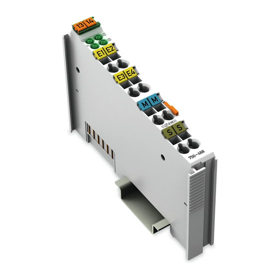
750-468 [4 AI DC 0-10 V, Single-Ended] • 7 View 2 I/O Modules 2.1 Analog Input Modules 2.1.1 750-468 [4 AI DC 0-10 V, Single-Ended] 4-Channel Analog Input Module (0-10V, Single-Ended) 2.1.1.1 View 13 14 Function AI 1 Function AI 2... -
Page 8: Description
This module has no power contacts. For field supply to downstream I/O mod- ules, a supply module will be needed. The analog input module 750-468 and its variations can be used with all cou- plers/controllers of the WAGO-I/O-SYSTEM 750 (except for the economy types 750-320, -323, -324 and -327). -
Page 9: Display Elements
750-468 [4 AI DC 0-10 V, Single-Ended] • 9 Display Elements 2.1.1.4 Display Elements Channel Designation State Function No operational readiness or the internal data bus communica- Function tion is interrupted green AI 1 Operational readiness and trouble-free internal data bus... -
Page 10: Technical Data
10 • 750-468 [4 AI DC 0-10 V, Single-Ended] Technical Data 2.1.1.6 Technical Data Module Specific Data Number of inputs Voltage supply via system voltage DC /DC Current consumption (internal) 60 mA typ. Input voltage 35 V max. Signal voltage 0 V... -
Page 11: Process Image
! Documentation ! WAGO-I/O-SYSTEM 750 ! Sys- tem Description 2.1.1.7 Process Image The analog input module 750-468 and its variations transmit 16-bit measured values and 8 status bits per channel. The digitalized measured value is transmitted in a data word (16 bits) as input byte 0 (low) and input byte 1 (high) into the process image of the coupler / controller. -
Page 12: Standard Data Format
2.1.1.7.1 Standard Data Format For the standard module 750-468, the input voltage ranging from 0 V to 10 V is scaled on the numerical values ranging from 0x0000 to 0x7FF9. Process values of module 750-468... -
Page 13: Special Data Format
Process Image 2.1.1.7.2 Special Data Format To digitalize the measurement value, the variation 750-468/000-200 uses a format adapted for the S5 control systems using FB 250. For this variation, the input voltage ranging from 0 V to 10 V is scaled on the numerical values ranging from 0x1000 to 0x5001. - Page 14 WAGO Kontakttechnik GmbH & Co. KG Postfach 2880 • D-32385 Minden Hansastraße 27 • D-32423 Minden Phone: 05 71/8 87 – 0 Fax: 05 71/8 87 – 1 69 E-Mail: info@wago.com Internet: http://www.wago.com...
Need help?
Do you have a question about the 750-468 and is the answer not in the manual?
Questions and answers